Powering Wearables with Battery FPC Connectors
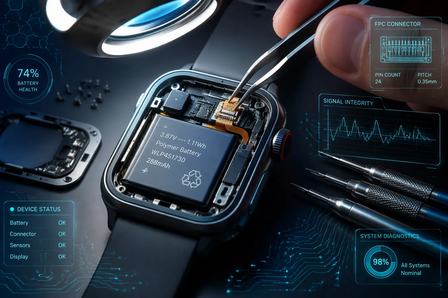
Battery FPC connectors are flexible, compact components that link a wearable device's battery to its internal circuits. Inside smartwatches and fitness bands, space is scarce, so these connectors route power through thin, bendable pathways instead of bulky wiring. That design choice keeps wearables slim against your wrist. The global wearable devices market reached USD 92.9 billion in 2025, according to Grand View Research, which shows how many users now depend on this hardware. Reliable connectors deliver a clear result: thinner, lighter, and more comfortable products. You gain a device that fits naturally and powers on every time.
Key Takeaways
Battery FPC connectors are thin and flexible. They save space in wearables like smartwatches.
These connectors link the battery to the device's circuits. They keep power flowing even when you move.
Flexible circuits are lighter than traditional wiring. They make wearables more comfortable to wear.
Battery FPC connectors handle vibration well. They stay connected during exercise and daily activities.
These connectors often have safety features. They prevent short circuits and overheating.
Choosing the right connector matters. Consider flexibility, current rating, and locking strength.
Future wearables will use flexible circuits for wireless features. They will also harvest energy from your body.
Battery FPC connectors enable slim, reliable, and safe wearable devices. They power the next generation of technology.
What Are Battery FPC Connectors?
A battery FPC connector is a flexible printed circuit connector that links the battery to the device's internal electronics. You find these components in small wearables such as smartwatches and fitness trackers, where every millimeter counts. The connector joins the battery to the flexible circuit inside a wearable device, allowing electricity to move from the battery to the device to power it. Its slim design lets it fit into compact spaces while maintaining the power connection.
Aspect | Detail |
|---|---|
Definition | A battery FPC connector links a battery to a flexible printed circuit. |
Primary function | The connector joins the battery to the flexible circuit inside a wearable device, allowing electricity to move from the battery to power it. |
Design benefit | Its slim design fits into compact spaces while maintaining the power connection. |
Flexible Circuits at a Glance
FPC stands for flexible printed circuit. These circuits use a thin polymer substrate instead of the rigid fiberglass board you see in larger electronics. Polyimide dominates production FPC manufacturing due to its thermal stability, chemical resistance, and mechanical toughness. PI films are commonly used in thicknesses of 25 µm, 50 µm, 75 µm, or 125 µm.
Manufacturers build the conductive layer from copper. Rolled annealed copper is preferred for dynamic flex applications because its fine-grain crystalline structure resists fatigue cracking under repeated bending better than electrodeposited copper. Electrodeposited copper costs less and suits static applications where the board is bent once during installation and remains fixed. Copper thickness is commonly 12 µm, 18 µm, or 35 µm, depending on current-carrying requirements and target flexibility.
Adhesiveless construction has become the standard for high-reliability flexible circuits. Copper is bonded directly to the polyimide substrate through sputtering or casting, producing thinner laminates with improved impedance control compared to adhesive-based constructions, which use thermosetting epoxy or acrylic adhesive typically 15–25 µm thick.
To address the use of adhesives in copper clad flex laminate, "adhesiveless" constructions were developed. Previously, copper layers were bonded to the polyimide core with either an acrylic or modified epoxy adhesive. An adhesiveless laminate has the copper directly attached to the polyimide core. Eliminating the adhesive bond layers allows for thinner constructions and more flexible design with vastly improved reliability. In addition, adhesiveless copper clad laminates have higher operating temperature ratings, higher copper peel strengths, and the desired reduced Z-Axis thermal expansion stress on vias.
Substrate material choice affects performance and cost. Polyimide handles approximately 260°C depending on grade and offers excellent dynamic flex suitability. Polyester costs less but handles only about 105°C and suits static bend applications. PEEK and LCP serve extreme environments and high-frequency designs respectively, though both carry higher costs.
How They Transfer Power
Electricity flows from the battery through the connector's metal contacts into the flexible circuit traces. Those traces carry current to the device's processor, display, sensors, and other components. The connector maintains a steady power path despite the bending and flexing that occurs during normal wear.
Contact resistance matters here. A well-designed connector keeps resistance low so that power reaches the circuit with minimal loss. The narrow pitch of these connectors allows multiple signal and power lines in a small area. Vibration resistance keeps the connection stable when you move your wrist during exercise or daily activity.
Uses in Wearable Technology
Smartwatches and fitness trackers represent the most common applications for battery FPC connectors. These devices pack a battery, display, sensors, and wireless radios into a case that sits on your wrist. The connector must fit within that tight envelope while surviving constant motion.
Wearable technology also includes medical monitors, smart glasses, and hearables. Each application demands reliable power delivery in a package that disappears against your body. Flexible connectors solve this problem by routing power through pathways that bend with the device rather than breaking under stress.
The table below summarizes common substrate options for these flexible circuits.
Substrate Material | Approx. Max Temp | Flex Suitability | Relative Cost | Typical Use |
|---|---|---|---|---|
Polyimide (PI) | ~260°C (grade-dependent) | Excellent — dynamic flex | Higher | Standard high-performance FPC |
Polyester (PET) | ~105°C | Static bend only | Lower | Cost-sensitive, low-temp applications |
PEEK | ~250°C | Good | High | Extreme environments |
LCP | ~280°C | Good | High | High-frequency, millimeter-wave |
You gain several advantages from this architecture. The device stays thin and light because the connector adds minimal bulk. Power transfer remains efficient because the copper traces and contacts are engineered for low resistance. The connection survives millions of flex cycles because the materials resist fatigue. These benefits explain why battery FPC connectors appear in nearly every compact wearable on the market today.
Design Features of Battery FPC Connectors
Flexibility and Compact Footprint
You need a power path that bends without breaking when you design a wearable device. Battery FPC connectors solve this problem through their base materials. Manufacturers build the flexible circuit on a polyimide substrate with rolled-annealed copper foil. This combination allows repeated bending and folding without cracking the conductive traces. The connector itself measures just 0.6 mm thick, which enables thinner and lighter wearables. That dimension matters when you fit a battery, display, and sensors into a watch case.
A single-row terminal layout reduces the mounting area by nearly half compared to multi-row designs. This saving gives you more room for the battery or other components. Small connectors with this profile fit into spaces where traditional wiring cannot reach. The result is a device that stays slim against your wrist while maintaining a reliable power path.
Narrow Pitch and Vibration Resistance
Wearables endure constant motion during exercise and daily activity. A battery fpc connector must hold its electrical contact despite that movement. Multi-contact designs maintain stable contact during shocks and vibration. Each contact point shares the current load, which reduces stress on any single terminal. This architecture keeps your device powered when you run, lift, or gesture.
Narrow pitch technology packs more contacts into a smaller area. You gain multiple power and signal lines without expanding the connector footprint. Some battery fpc connectors now carry up to 6 A current ratings. That capacity supports bright displays, camera flashes, and fast charging in a slim package. The narrow pitch also shortens the current path, which lowers resistance and improves efficiency.
Secure Locking and Battery Retention
A loose connection cuts power to your device at the worst moment. Battery fpc connectors address this risk through mechanical locking features. Center lock designs and direct connection options keep the mating halves engaged. Right-angle and straight-angle shapes give you flexible placement options during assembly. These features enable one-handed assembly, which speeds up production and reduces errors.
Zif connectors and other flexible connectors often include a locking mechanism that secures the flexible circuit. This lock prevents accidental disconnection when the device experiences drops or impacts. Power and signal terminals integrated in one piece add functionality while saving space. Thermal fuses, overcurrent circuits, and temperature sensors provide an extra layer of protection. These safety components help prevent overheating and short-circuit failures. The combination of secure locking and built-in protection keeps your wearable running safely through years of use.
Why Wearable Devices Rely on Flexible Circuits
Enabling Slim, Lightweight Designs
Space inside a smartwatch or fitness band disappears fast. You fit a battery, a display, sensors, and a radio into a case that rests on a wrist. Rigid boards fight that goal because they cannot bend around a curved shell. A flexible printed circuit solves the problem by folding into corners and wrapping around internal parts. Flexible-circuit materials take about 10% of the size and weight of wired or rigid interconnect solutions, according to industry data. That reduction lets you shrink the housing without cutting battery capacity.
The comparison below shows where flexible and rigid-flex designs beat rigid PCB assemblies in wearable products.
Advantage | Why It Matters in Wearables |
|---|---|
Reduced size and weight | Eliminating individual boards, connectors, and cable harnesses directly reduces package size and weight. |
Higher reliability | Fewer connectors, wires, and soldered joints mean fewer points subject to stress from vibration, shock, or motion. |
Better bend capability | Flexible regions can use tighter bend radii than rigid boards, enabling curved or folded product shapes. |
Cost recovery | Fewer parts and less assembly time can offset higher manufacturing cost and improve product reliability. |
A rigid-flex board takes this idea further. You place stable rigid sections under the processor and use flexible sections for antennas and sensors. This hybrid layout fits tight spaces such as smart rings and AR glasses. Flexible traces also route high-speed signals across curved frames without bulky wiring. Each removed connector and solder joint is one less failure point during a drop.
Improving Power Transfer Efficiency
Power must travel from the battery to the processor with minimal loss. Every connector, wire, and solder joint in that path adds resistance and steals a small amount of energy. Battery fpc connectors shorten that path by joining the battery directly to the flexible circuit. Fewer interfaces mean lower total resistance and less heat at each junction. Your device then converts more stored energy into useful work.
A flexible circuit also holds its electrical properties while it bends. Polyimide materials tolerate constant movement while maintaining reliability, so contact resistance stays stable through millions of flex cycles. That stability matters for steady power delivery. A loose or corroded joint causes voltage drops, and the device may reset or shut down. Multi-contact designs share the current load across several terminals, which lowers stress on any single point. Narrow pitch layouts shorten the current path even more. The result is efficient transfer from cell to screen, sensor, and radio.
Boosting Comfort and Durability
Comfort depends on weight and fit. Flexible PCBs can weigh under 0.5 g, so they add almost nothing to the load on your wrist. Circuits also bend to match wrist or body curves. That conformability helps sensors stay in contact with skin for accurate readings. A rigid board cannot follow a curved surface, and it creates pressure points against the arm.
Durability follows the same logic. Rigid boards need many connectors, solder joints, and wire contacts. Flexible and rigid-flex designs reduce or eliminate those interfaces, which improves reliability in drops and demanding use. Rigid-flex sections provide durable, shock-absorbing areas for components while flexible sections allow needed bending. Fewer mechanical joints mean fewer places where vibration can loosen a connection. You gain a device that survives daily motion, sweat, and impact.
These benefits explain the growing demand for battery fpc connectors in small and powerful wearables. Designers of wearable technology choose flexible connectors because they cut weight, hold a stable connection, and absorb motion. The same traits support the next generation of wearable devices, from smartwatches to medical monitors. When you select a connector for a compact product, weigh flexibility, contact resistance, and locking strength together. Those three factors decide whether your wearable stays comfortable and reliable for years.
Battery FPC vs. Traditional Connectors
Assembly and Space Efficiency
Traditional wire-to-board connectors demand manual routing and soldering. Each wire needs a terminal, a housing, and a solder joint. That process consumes time and floor space on the assembly line. Battery fpc connectors replace this tangle with a single plug-in action. You align the flex tail, insert it, and lock it down. The 0.6 mm profile of these connectors frees vertical room inside a watch case. A rigid connector block cannot match that saving.
Zif connectors add another layer of efficiency. You lift the actuator, slide the flex circuit into place, and press the lock shut. This zero-insertion-force action prevents damage to the delicate traces during mating. The narrow pitch of battery fpc connectors also packs more contacts per square millimeter. You route power and signals through one interface instead of several. That consolidation cuts part count and simplifies your bill of materials.
Vibration Resistance and Longevity
A wearable moves with every step, swing, and gesture. Traditional connectors rely on friction between metal pins and receptacles. That friction weakens over time. Vibration loosens the mating halves, and contact resistance climbs. Battery fpc connectors use positive locking mechanisms instead. The lock holds the flex tail against the contacts under constant motion. Multi-contact designs share the electrical load across several terminals. No single point carries the full current.
Flexible connectors also absorb mechanical stress through their polymer substrate. Polyimide withstands repeated bending without cracking the copper traces. A rigid connector concentrates stress at the solder joint. That joint eventually fatigues and fails. The flex design distributes strain along the bend radius. Your device keeps its connection through millions of flex cycles. This durability explains why wearables with flexible circuits outlast those with rigid wiring.
Safety and Thermal Behavior
Heat builds at every resistive junction. A loose traditional connector raises resistance and generates local hot spots. Battery fpc connectors maintain low contact resistance through secure locking and multi-point contact. Lower resistance means less wasted energy as heat. The polyimide substrate also tolerates temperatures up to approximately 260°C depending on grade. That thermal stability protects the circuit during a fault event.
High current ratings up to 6 A support fast charging without overheating the interface. Thermal fuses and overcurrent circuits integrated into the connector add another safeguard. These components cut power when current exceeds safe limits. A traditional connector lacks this built-in protection. You must add external fuses, which consume board space. The integrated approach saves room and improves safety. For any wearable, this combination of low heat generation and built-in protection keeps the user safe.
Safety and Selection for Wearable Power Connectors
Avoiding Short Circuits and Reverse Insertion
A short circuit can destroy a battery and injure the user. You prevent this risk through connector design and assembly discipline. Battery fpc connectors use keyed housings that allow only one mating orientation. The key blocks reverse insertion, so power cannot flow through the wrong path. Positive locking mechanisms hold the flex tail in place and stop partial mating. A partial mate creates arcing and local heating at the contacts.
Moisture and salt from sweat also cause shorts across exposed traces. You shield copper traces with polyimide or liquid photoimageable coverlays. These layers block moisture, dust, sweat, and humidity from reaching the conductors. Place exposed charging contacts where fluid can drain and where the user can clean them. Validate plating and sealing against real exposure conditions. Test continuity inside the assembled case, then test charging under the expected current. These checks confirm a safe and steady connection before the product ships.
Managing Current, Voltage, and Heat
Heat is the enemy of every compact power path. You control it by matching the connector to the electrical load. Count signal, ground, and power pins separately when you review current ratings. Use the supplier's per-contact rating for each pin. Do not multiply one pin rating by the total pin count. Adjacent loaded contacts generate heat together, and that heat reduces the safe limit for each pin.
Voltage compatibility matters just as much. Match voltage levels and communication interfaces to prevent system mismatches. For battery-powered devices, select low-power, high-efficiency components to extend battery life. Choose high-conductivity materials, high-Tg polyimide, and matching CTE to reduce overheating and thermal stress. Select adhesives that withstand reflow temperatures up to 260°C so the layers stay bonded during assembly. A battery fpc connector rated for high current supports fast charging without overheating the interface.
Matching Connectors to Device Environments
Every wearable product imposes its own operating conditions. You match material and manufacturing controls to temperature, mechanical stress, and expected service life. Design around bend radius, material thickness, component placement, and protective layers. In complex assemblies, rigid-flex constructions improve component stability and assembly yields compared with pure flex. For demanding applications, flexible connectors should support vibration resistance and stable electrical performance in confined spaces.
The table below summarizes the main selection criteria for battery fpc connectors in wearables.
Category | Criterion | Selection Guidance |
|---|---|---|
Electrical | Electrical load | Choose material and circuit structure for the expected load and stable performance. |
Electrical | Voltage compatibility | Match voltage levels and interfaces to prevent mismatches. |
Environmental | Operating temperature | Match materials to temperature, mechanical conditions, and service life. |
Environmental | Moisture and dust | Use polyimide or liquid photoimageable coverlays to shield traces. |
Environmental | Skin contact | Place charging contacts to drain and clean; validate plating and sealing. |
Smartwatches and fitness trackers face sweat, motion, and repeated charging. Test contact during handling, service cycles, and relevant environmental exposure. These steps keep power flowing in every wearable you design.
Future Power Trends for Wearable Devices
Flexible Circuits for NFC and Bluetooth
You will see tighter integration between power delivery and wireless communication in the next generation of wearables. Flexible printed circuit boards now carry both power traces and antenna patterns on the same substrate. This dual-purpose design eliminates separate components and frees space inside the device. A battery fpc connector can route current to the radio while the same flexible layer handles NFC or Bluetooth signals. Manufacturers build these circuits on polyimide, which handles the high frequencies these protocols demand.
The connector itself must support both functions without adding bulk. Narrow pitch layouts let you run power and signal lines side by side. This approach keeps the device thin and maintains reliable contact through motion. Your smartwatch or fitness band then communicates with phones and payment terminals without extra hardware.
Energy Harvesting and Rapid-Charging Storage
Future wearables will draw power from sources beyond the battery. Thermoelectric generators convert body heat into small amounts of electricity. Piezoelectric materials capture energy from movement and vibration. These harvesting methods supplement the battery and extend runtime between charges. Flexible pcbs integrate these harvesters directly into the device structure.
Storage technology is advancing alongside harvesting. Flexible supercapacitors charge in seconds and tolerate thousands of cycles. You gain rapid top-ups during brief charging windows. Power sources may soon integrate into clothing or straps rather than sitting inside a case. This shift moves the battery fpc connectors into fabrics and accessories. Flexible connectors must then survive washing, stretching, and daily wear.
Body-Coupled Power Transmission
Body-coupled power transmission remains an emerging approach for powering batterless wearables. Intra-Body Power Transfer uses the human body as a conductive medium. Researchers have proposed galvanic coupling, magnetic coupling, and capacitive coupling methods. Capacitive coupling stands out as one of the most appealing options for wearable applications.
A Localized Capacitive Coupling system demonstrated a passive power receiver in a wearable form factor. Experiments with ten human subjects showed sufficient power delivery for intermittent workloads comparable to RFID systems. A mean path gain was consistently achieved at the hand and leg with limited sensitivity to inter-subject variation. A batterless wearable ring with a three-axis accelerometer was demonstrated, powered entirely through IBPT.
Body-coupled energy transfer occurs when extremely low frequency electric fields below 1 kHz are transmitted toward the human body upon contact with objects of different potentials. When a passive electrode attached to the body connects to a counter electrode with a different potential, electron movement causes potential distortion, creating a localized electric field in biological tissues.
Substantial challenges remain. Accurate models of capacitively coupled IBPT over realistic body channels are needed. Instrumentation must reliably quantify actual power delivered to a receiver. Current studies recruited small samples from engineering departments, all male, with limited body movements examined in controlled laboratory settings. Future work should investigate real-world conditions including clothing, sweating, and longer-term wear.
Battery fpc connectors enable compact, reliable power delivery in wearable technology. Miniaturization tops the list of benefits. Battery fpc connectors replace bulky wiring, letting you build thinner cases. Efficient power transfer follows: short traces and stable contacts cut energy loss. Safety completes the trio. Secure locks and thermal safeguards prevent shorts and overheating.
Flexible connector designs will shape the next generation of wearables. Smaller devices, tighter bend radii, and new charging methods all depend on flexible circuits. Body-coupled transmission and energy harvesting will extend this foundation. Expect future designs to evolve as those systems mature. The flexible circuit remains the backbone of wearable innovation.
FAQ
What exactly does a battery FPC connector do?
It links a battery to a device's flexible printed circuit. Power flows from the cell through the connector's metal contacts into copper traces. Those traces carry current to the processor, display, and sensors. The connector holds this path steady while the device bends and moves against your wrist.
Why not use standard wire connectors instead?
Traditional wire connectors need manual routing, terminals, and solder joints. Each joint adds resistance and a potential failure point. A battery FPC connector replaces that tangle with one plug-in action. You save assembly time, cut part count, and free vertical room inside a slim case.
How thin can these connectors get?
The connector itself measures just 0.6 mm thick. That profile lets you fit a battery, display, and sensors into a watch case without stacking bulky hardware. Flexible-circuit materials also take about 10% of the size and weight of wired or rigid interconnect solutions, according to industry data.
Which substrate should I choose for my design?
Polyimide suits most wearables because it handles roughly 260°C and survives dynamic flex. Polyester costs less but handles only about 105°C and works for static bends. PEEK and LCP serve extreme or high-frequency designs at higher cost. Match the material to your temperature and bending needs.
Can these connectors handle fast charging?
Yes, some battery FPC connectors carry current ratings up to 6 A. That capacity supports bright displays and fast charging in a slim package. Multi-contact designs share the load across several terminals, which lowers stress on any single point and reduces heat buildup at the interface.
How do you prevent a short circuit in a sweaty device?
Keyed housings allow only one mating orientation, which blocks reverse insertion. Polyimide or liquid photoimageable coverlays shield copper traces from moisture, dust, and sweat. Place exposed charging contacts where fluid can drain and where you can clean them. Validate plating and sealing against real exposure conditions.
What keeps the connection stable during exercise?
Positive locking mechanisms hold the flex tail against the contacts under constant motion. Multi-contact designs share the electrical load, so no single terminal carries the full current. The polyimide substrate also absorbs mechanical stress along the bend radius instead of concentrating it at one solder joint.
Will flexible circuits support wireless features too?
Yes. Flexible printed circuit boards now carry both power traces and antenna patterns on the same substrate. A battery FPC connector routes current to the radio while the same flexible layer handles NFC or Bluetooth signals. This dual-purpose design eliminates separate components and frees space inside the device.
