Choosing the Right Materials for Ceramic Hybrid PCB Success
For ceramic hybrid pcb success, it’s essential to select ceramic materials that align with your application’s specific requirements. The optimal ceramic substrate enhances both thermal dissipation and mechanical durability, which are critical for high-performance ceramic hybrid pcb designs. Each ceramic type provides distinct electrical and thermal properties, directly impacting signal transmission and electromagnetic interference. By matching the coefficient of thermal expansion between copper and ceramic, you can prevent delamination and ensure long-term reliability in your ceramic hybrid pcb. LT CIRCUIT leverages advanced ceramic solutions to help you achieve efficient, cost-effective ceramic hybrid pcb designs with consistently proven performance.
Key Takeaways
Select ceramic materials based on your application’s thermal, electrical, and mechanical needs for optimal performance.
Prioritize high thermal conductivity materials to enhance heat dissipation and protect sensitive components in high-power applications.
Ensure the coefficient of thermal expansion matches between copper and ceramic to prevent delamination and improve reliability.
Utilize advanced testing methods like thermal cycling and X-ray inspection to validate the quality and performance of your ceramic PCBs.
Consult with experts like LT CIRCUIT to choose the right materials and achieve efficient, cost-effective ceramic hybrid PCB designs.
Ceramic Hybrid PCB Materials
Ceramic hybrid pcb materials play a vital role in shaping the reliability and performance of your pcb design. You need to choose hybrid pcb materials that match your application’s requirements for thermal management, electrical insulation, and mechanical strength. LT CIRCUIT leads the industry by offering advanced ceramic pcbs and hybrid pcb materials that support demanding applications. You can achieve higher performance and longer lifespan by understanding the key properties and types of ceramic pcbs available.
Key Properties
When you select hybrid pcb materials for ceramic pcbs, you should focus on several critical properties. These properties determine how well your pcb will perform in harsh environments and high-power applications.
High thermal conductivity helps your pcb dissipate heat efficiently. Ceramic pcbs can reach values from 25 to 330 W/(m·K), which protects sensitive components from overheating.
Low coefficient of thermal expansion (CTE) keeps your pcb stable when temperatures change. This stability prevents warping and delamination.
Excellent thermal insulation ensures that heat does not travel through the substrate, keeping your components safe.
Inorganic material composition gives ceramic pcbs strong chemical resistance and durability for long-term use.
Tip: When you prioritize these properties, you boost the performance and reliability of your ceramic hybrid pcb.
Material Types
You have several options when choosing hybrid pcb materials for ceramic pcbs. Each material offers unique strengths for different applications and performance needs.
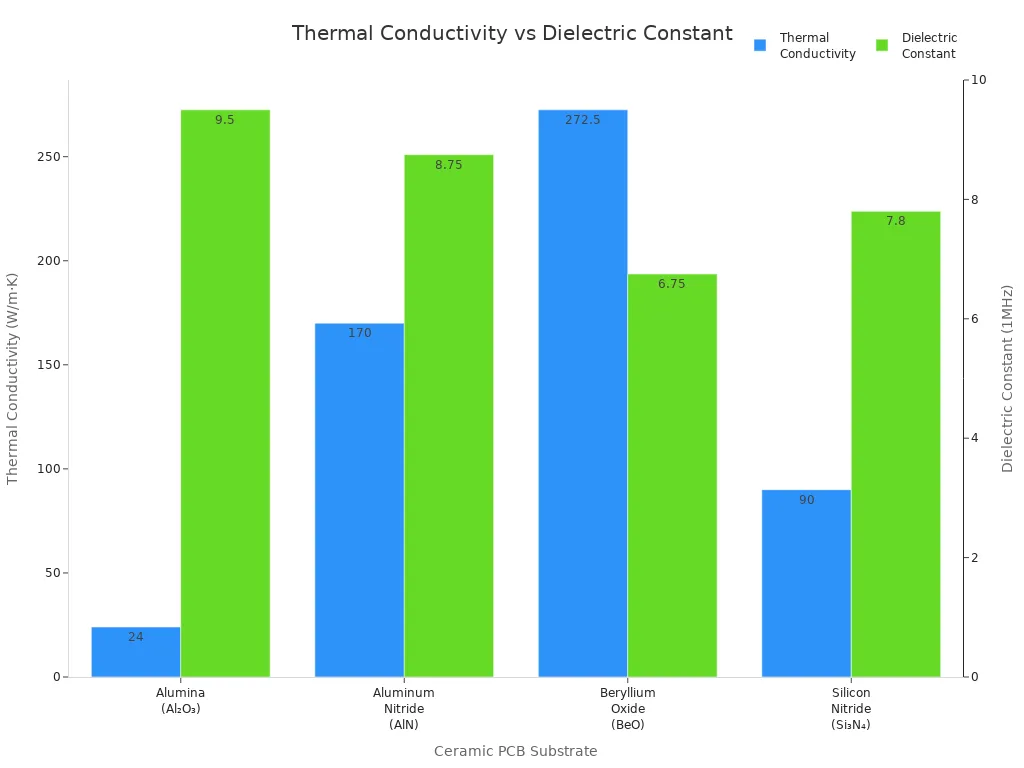
Ceramic PCB Substrate | Thermal Conductivity (W/m·K) | Dielectric Constant (1MHz) | Typical Uses | Key Strengths |
|---|---|---|---|---|
Alumina (Al₂O₃) | ≥ 24 W/m·K | 9 – 10 | LED modules, power boards | Affordable, good all‑rounder |
Aluminum Nitride (AlN) | ≥ 170 W/m·K | ≈ 8.5 – 9 | High‑power inverters, RF | Very high heat transfer, CTE matched |
Beryllium Oxide (BeO) | ≈ 260 – 285 W/m·K | ≈ 6.5 – 7 | Laser drivers, aerospace | Highest conductivity, strict safety |
Silicon Nitride (Si₃N₄) | ≈ 90 W/m·K | 7.8 | EV modules, harsh electronics | Tough, thermal‑shock resistance |
You can find the following hybrid pcb materials in ceramic pcbs:
Alumina (Aluminum Oxide) pcbs provide solid thermal conductivity, mechanical strength, and electrical insulation. You often use them in power electronics, LED lighting, and RF devices.
Aluminum Nitride (AlN) pcbs deliver higher thermal conductivity than alumina. You choose them for high-power applications such as LED lighting and microwave devices.
Silicon Carbide (SiC) pcbs offer exceptional thermal conductivity and stability at high temperatures. You rely on them for automotive and aerospace applications.
Beryllium Oxide (BeO) pcbs feature extremely high thermal conductivity. You use them in high-current devices, but they require strict safety controls.
Hybrid ceramic pcbs combine multiple ceramic materials to optimize performance for specific applications.
LTCC (Low-Temperature Co-Fired Ceramic) pcbs excel in RF performance. You select them for wireless communication and automotive electronics.
You should match the material type to your application’s thermal, electrical, and mechanical demands. LT CIRCUIT provides a wide selection of hybrid pcb materials, helping you achieve the best performance for your ceramic hybrid pcb design.
Design Considerations
When you plan a ceramic hybrid pcb, you need to focus on several design considerations that impact both performance and reliability. The right choices in stack-up, substrate, copper thickness, and surface finish help you achieve the best results for your application. LT CIRCUIT offers a wide range of options to support your unique needs, ensuring your pcb meets the highest standards.
Stack-Up and Substrates
The stack-up defines how you arrange the layers in your pcb. This arrangement affects signal integrity, thermal management, and overall performance. You should select a stack-up that matches your application’s requirements, especially for high-frequency or high-power uses.
Aspect | Description |
|---|---|
Hybrid Stack-Up | Built with specialized material only on selected layers to meet design needs. |
Signal Integrity Techniques | Controlled impedance and appropriate grounding to maintain signal integrity. |
Layer Isolation | Critical signal layers should be well isolated and properly routed to minimize interference and crosstalk. |
You need to consider the materials and layer arrangement carefully. For example, hybrid stack-ups use ceramic materials on specific layers to optimize thermal and electrical properties. Controlled impedance and proper grounding help you maintain signal integrity, which is vital for high-frequency circuits.
Note: Careful stack-up planning reduces interference and improves the integrity of your signals.
Substrate choice also plays a key role in your pcb’s performance. Ceramic substrates like alumina (Al₂O₃) and aluminum nitride (AlN) offer much higher thermal conductivity and mechanical strength than standard FR4. This means your pcb can handle more heat and stress, making it ideal for demanding environments.
Property | Ceramic Substrates (AlN, Al₂O₃) | FR4 |
|---|---|---|
Thermal Conductivity | 0.3-0.5 W/m·K | |
Mechanical Strength | High rigidity, resistant to stress | Lower rigidity |
Electrical Insulation | Low dielectric loss, high breakdown voltage | Moderate insulation |
Ceramic pcbs provide superior thermal management, high mechanical strength, and excellent electrical insulation. These features support high-frequency and high-power applications, where reliability and performance matter most. LT CIRCUIT helps you select the right substrate for your design, ensuring your pcb meets your thermal and electrical needs.
Copper and Surface Finishes
Copper thickness and surface finish are important factors in your pcb design. The right copper thickness ensures your pcb can handle the required current and dissipate heat effectively. Surface finishes protect the copper and improve solderability, which is essential for reliable assembly.
Surface Finish | Thickness Range (µm) | Key Benefits |
|---|---|---|
Immersion Tin | 0.8 to 1.2 | Good solderability, compatibility with lead-free processes, strong intermetallic compounds for reliability |
Immersion Silver | 0.12 to 0.4 | Excellent solderability, low contact resistance, suitable for high-frequency applications |
ENEPIG | 3 to 5 (Nickel), 0.05 to 0.15 (Palladium), 0.03 to 0.05 (Gold) | Excellent solderability, wire bondability, long-term reliability, compatibility with multiple assembly technologies |
You should choose a surface finish based on your application’s needs. For example, immersion silver works well for high-frequency circuits because it offers low contact resistance. ENEPIG provides long-term reliability and supports multiple assembly methods, making it a strong choice for advanced designs.
Surface roughness affects solder joint strength. Smoother finishes create stronger joints and better reliability.
Corrosion resistance is important for long-term performance, especially in harsh environments. Finishes like ENIG protect against oxidation.
The right finish improves solder flow and adhesion, which helps you achieve reliable electrical connections.
LT CIRCUIT offers a variety of copper thicknesses and surface finishes to match your design requirements. You can select from immersion tin, immersion silver, ENEPIG, and more, ensuring your pcb meets both performance and reliability goals.
Tip: Always match your copper thickness and surface finish to your application’s current, thermal, and assembly needs.
By considering stack-up, substrate, copper, and surface finish, you can optimize your ceramic hybrid pcb for thermal management, signal integrity, and long-term reliability. LT CIRCUIT’s expertise in advanced materials and finishes helps you achieve the best possible results for your design.
PCB Thermal Design
Effective pcb thermal design helps you achieve reliable operation and long-lasting performance in your ceramic hybrid pcb. You need to manage heat carefully because high temperatures can damage components and reduce efficiency. Ceramic pcbs offer unique advantages for thermal management, making them ideal for demanding applications.
Thermal Conductivity
You should focus on thermal conductivity when selecting materials for your pcb. Ceramic substrates like alumina and aluminum nitride transfer heat much better than standard FR-4. This property allows your pcb to handle higher power levels and maintain stable performance.
Material Type | |
|---|---|
FR-4 | 0.3 - 0.5 |
Alumina-based DBC | 24 |
Aluminum nitride-based DBC | Over 170 |
Ceramic pcbs with high thermal conductivity support efficient heat dissipation. You can use these pcbs in high-power electronics, RF devices, and automotive modules. The improved thermal performance protects sensitive components and extends device lifespan. LT CIRCUIT specializes in high thermal conductivity solutions, helping you meet strict thermal requirements.
Tip: Use ceramic substrates to prevent hotspots and maintain consistent performance in your pcb.
Thermal Management Strategies
You need strong thermal management strategies to optimize your pcb. Ceramic hybrid pcb designs allow you to combine different materials for maximum heat control. You can use thicker copper layers, thermal vias, and advanced stack-ups to direct heat away from critical areas.
Ceramic pcbs excel in high-density layouts, preventing overheating under heavy loads.
You can rely on ceramic pcbs for stable operation in extreme conditions.
LT CIRCUIT offers a thermal design guide to help you select the best strategies for your application.
The efficient heat dissipation in ceramic pcbs improves device performance and reliability. You see these benefits in LEDs, automotive electronics, and RF modules. By following a proven thermal design guide, you ensure your pcb meets industry standards and delivers consistent results.
Ceramic PCBs Benefits
Performance Advantages
You gain several important advantages when you choose ceramic pcbs for your pcb design. Ceramic hybrid pcb technology improves performance in ways that standard materials cannot match. You see better thermal management, higher reliability, and stronger mechanical properties.
Here is a comparison of key performance metrics between ceramic pcbs and conventional pcbs:
Performance Metric | Ceramic PCBs | Conventional PCBs (FR-4) |
|---|---|---|
Thermal Conductivity | 0.25 W/m·K | |
High-Temperature Resistance | Up to 800°C | 130–170°C (glass-transition) |
Coefficient of Thermal Expansion | 2.6–3.5 ppm/°C | 14–17 ppm/°C |
Electrical Insulation | 10 kV/mm to over 20 kV/mm | Lower dielectric strength |
Mechanical Strength | High rigidity and toughness | Prone to warping and cracking |
You notice that ceramic pcbs deliver exceptional thermal conductivity. This feature helps your pcb dissipate heat quickly, which prevents hotspots and protects sensitive components. You also benefit from high-temperature resistance, allowing your pcb to operate in harsh environments. The low coefficient of thermal expansion reduces mechanical stress during thermal cycling. Superior electrical insulation lets your pcb handle high voltages safely. Mechanical strength and durability keep your pcb intact even under physical stress.
Tip: You can rely on ceramic hybrid pcb designs for stable performance in high-power and high-frequency applications.
Application Areas
You find ceramic pcbs in many industries because of their unique thermal and mechanical properties. These pcbs support a wide range of applications that demand reliability and efficiency.
LED technology uses ceramic pcbs for efficient thermal dissipation in high-power lighting.
Automotive industry relies on ceramic pcbs for power electronics and sensors that need durability.
Telecommunications benefit from ceramic pcbs in RF and microwave circuits with low dielectric loss.
Aerospace and defense use ceramic pcbs for radar and avionics that must perform in extreme conditions.
Medical devices depend on ceramic pcbs for imaging and diagnostic equipment that require safety and reliability.
Power electronics use ceramic pcbs to handle high power densities with excellent thermal management.
Consumer electronics include ceramic pcbs in smartphones and laptops for high performance in compact designs.
Industrial applications use ceramic pcbs in robotics and automation systems for robustness.
You see that ceramic hybrid pcb solutions help you meet the demands of advanced applications. You achieve better thermal control, improved reliability, and longer lifespan for your pcb.
Material Comparison
Alumina vs. AlN
When you choose hybrid pcb materials for your ceramic pcbs, you often compare alumina and aluminum nitride. Both materials offer strong thermal and electrical properties, but they serve different needs in pcb design. You can see the main differences in the table below:
Property | Alumina (Al₂O₃) | Aluminum Nitride (AlN) |
|---|---|---|
Thermal Conductivity | Lower thermal conductivity | Higher thermal conductivity |
Electrical Insulation | Slightly better insulation | Excellent insulation |
Mechanical Strength | Superior strength | Good mechanical strength |
Alumina gives you reliable electrical insulation and strong mechanical strength. You often use it in multilayer ceramic pcbs where cost matters more than maximum thermal performance. Aluminum nitride stands out for its high thermal conductivity. This makes it ideal for pcbs that must handle intense heat, such as power modules or RF devices.
Cost and manufacturability also play a role in your choice of hybrid pcb materials. Here is a quick comparison:
Metric | Alumina | AlN |
|---|---|---|
Relative Cost | More cost-effective | Higher cost |
Manufacturability | More challenging to machine | More challenging to machine |
You find alumina more cost-effective for applications that do not need extreme thermal management. Both materials present machining challenges, so you need advanced hybrid pcb materials expertise for precise fabrication.
Tip: Select alumina for general-purpose ceramic pcbs and choose AlN when your pcb requires top-level thermal performance.
LTCC and Hybrids
You can also explore LTCC and hybrid ceramic pcb technologies for advanced applications. LTCC stands for Low-Temperature Co-Fired Ceramic. This technology uses hybrid pcb materials that support high-frequency and high-density circuits. You benefit from several advantages:
Advantage | Description |
|---|---|
Environmentally friendly | Uses sustainable materials and processes |
Compatibility | Adapts to many application scenarios |
Production efficiency | Supports mass production |
Operating costs | Reduces costs through productivity |
High quality factor | Delivers strong RF and microwave performance |
Miniaturization and density | Enables compact, lightweight pcb designs |
Excellent electrical properties | Offers a wide dielectric constant range and high-frequency stability |
High conductivity | Uses Ag and Cu for better circuit quality |
Good temperature characteristics | Maintains stability with a low coefficient of thermal expansion |
High-temperature characteristics | Handles high current and temperature for reliability |
Non-continuous production process | Allows substrate inspection for better yield and lower costs |
You see LTCC and hybrid ceramic pcbs in aerospace, automotive, telecommunications, medical, and industrial applications. These hybrid pcb materials give you reliable performance in harsh environments and high-frequency systems. You can trust advanced hybrid pcb materials to deliver the thermal, electrical, and mechanical benefits your pcb needs.
Selection Criteria
Performance Needs
You need to focus on several key factors when selecting materials for ceramic hybrid pcb designs. The right choice helps your pcb deliver strong performance in demanding environments. You should look at how each ceramic material supports thermal management, electrical insulation, and mechanical strength. These properties matter most in power electronics, automotive, and medical applications.
Here is a table that shows the main performance criteria for ceramic pcbs:
Performance Criteria | Description |
|---|---|
Thermal Conductivity | Essential for thermal management; AlN and BeO outperform Alumina for high-power applications. |
Electrical Insulation | High dielectric strength is crucial for isolation; low dielectric constant preferred for RF. |
Coefficient of Thermal Expansion (CTE) | Must match components to prevent stress; AlN aligns well with silicon. |
Mechanical Strength & Toughness | Alumina offers good toughness; BeO is fragile and should be avoided unless necessary. |
Cost Considerations | Balance cost with performance; Alumina is low-cost, AlN is high-cost for critical applications. |
Manufacturing Compatibility | Different materials suit different processes; LTCC allows complex structures. |
You should select ceramic pcbs with high thermal conductivity for better heat dissipation. Electrical insulation keeps your pcb safe from voltage spikes. Matching the CTE between ceramic and other pcb materials prevents warping. Mechanical strength ensures your pcb lasts longer in harsh conditions. You need to balance cost and performance for your specific applications.
Tip: Always match the ceramic material to your pcb’s thermal and electrical needs for the best results.
Cost and Manufacturability
You must consider both cost and manufacturability when choosing ceramic hybrid pcb materials. The price of ceramic pcbs depends on the type of ceramic, the complexity of the design, and the manufacturing process. Some ceramic materials, like aluminum nitride and beryllium oxide, cost more because they offer higher thermal performance. Manufacturing ceramic pcbs requires special equipment and skilled workers.
Ceramic pcbs use expensive materials, which increases the overall cost of your pcb.
The manufacturing process for ceramic pcbs is complex and needs advanced technology.
Hybrid ceramic pcbs combine different materials to improve performance and make production more cost-effective.
You should work with a trusted partner who understands ceramic pcb manufacturing. LT CIRCUIT helps you choose the right ceramic materials and design for your pcb. You get reliable performance and cost control for automotive, medical, and other advanced applications.
Design Challenges
Warpage and Shrinkage
You face several design challenges when working with ceramic pcbs. Warpage and shrinkage often appear during pcb manufacturing. These problems can affect the reliability and performance of your ceramic hybrid pcb. Warpage means the pcb bends out of its plane. Shrinkage happens when the ceramic material contracts during curing or thermal cycles.
Here is a table that shows common warpage and shrinkage issues in ceramic pcbs:
Warpage Issue | Description | Causes |
|---|---|---|
Out-of-plane bending | Warpage refers to the deformation of a packaged device. | CTE mismatch, cure/compression shrinkage, chemical shrinkage during curing. |
Reliability problems | Warpage can lead to delamination and chip cracking. | Molding process issues. |
Manufacturing problems | Poor solder ball coplanarity in PBGA devices. | Warpage affecting placement during reflow soldering. |
Warp modes | Includes concave, convex, and combination modes. | Variations in package geometry and material composition. |
Thermochemical shrinkage | Chemical shrinkage at high curing temperatures. | Increases in glass transition temperature and thermal expansion coefficient changes. |
You need to control warpage and shrinkage to keep your pcb flat and stable. If you ignore these issues, you may see delamination, cracking, or poor solder connections. You can reduce warpage by matching the coefficient of thermal expansion between ceramic and other pcb materials. Careful process control helps you avoid shrinkage during high-temperature steps.
Tip: Always monitor your ceramic pcb during manufacturing to catch warpage early.
Stress and Compatibility
You must also manage stress and compatibility in ceramic hybrid pcb assemblies. Different ceramic materials have unique properties. These differences can create mechanical stress and affect electrical performance. You need to match material properties to avoid problems during thermal cycling and assembly.
The table below lists material properties that contribute to stress and compatibility challenges in ceramic pcbs:
Material Property | Contribution to Challenges |
|---|---|
Coefficient of Thermal Expansion (CTE) | Causes mechanical stress and warpage due to mismatches during thermal cycling. |
Dielectric Constant (Dk) | Affects electrical performance and compatibility with other materials. |
Thermal Stability | Ensures reliability during high-temperature processes. |
Material Variability | Leads to inconsistencies in performance and reliability. |
You should select ceramic materials with similar CTE values to reduce stress. A stable dielectric constant helps you maintain signal integrity in your pcb. High thermal stability ensures your pcb performs well in demanding environments. You can improve compatibility by choosing ceramic pcbs with consistent material properties.
Note: Careful material selection and process control help you avoid stress and compatibility issues in ceramic hybrid pcb designs.
Best Practices
Simulation and Testing
You can improve the reliability of your ceramic pcbs by using advanced simulation and testing protocols. Simulation tools let you model electrical, thermal, and mechanical properties before you build your pcb. You can spot issues early and adjust your design for better performance. These tools help you predict how your ceramic pcb will handle heat, stress, and signal flow.
Advanced modeling tools simulate thermal and electrical behavior.
You can identify weak spots and fix them before production.
This approach reduces errors and boosts the performance of your final pcb.
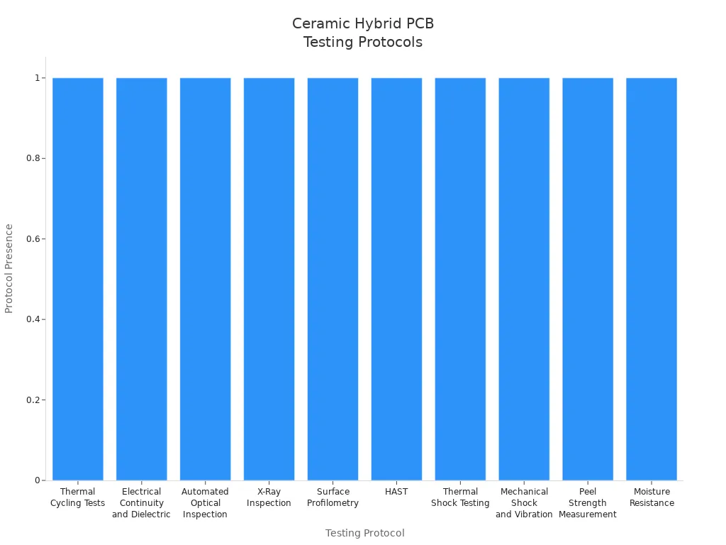
Testing protocols play a key role in validating ceramic pcbs. You should use a range of tests to check for defects and ensure quality. The table below shows common testing protocols for ceramic hybrid pcb validation:
Testing Protocol | Description |
|---|---|
Thermal Cycling Tests | Boards face temperature swings from -55°C to +150°C to verify via fill, metallization adhesion, and substrate bonding. |
Electrical Continuity and Dielectric Testing | High-voltage insulation resistance and continuity tests detect microcracks in multilayer ceramic pcbs. |
Automated Optical Inspection (AOI) | Finds metallization width, spacing defects, and paste spreading issues after screen printing and firing. |
X-Ray Inspection | Detects voids in vias or solder joints, especially in multilayer or high-density interconnect configurations. |
Surface Profilometry | Assesses the uniformity of conductive traces, especially after sputtering or plating. |
HAST (Highly Accelerated Stress Testing) | Accelerated aging with high humidity and temperature to check resistance to delamination. |
Thermal Shock Testing | Rapid hot and cold transfers reveal expansion mismatches between metal layers and ceramic substrates. |
Mechanical Shock and Vibration Testing | Finds weaknesses in lamination or substrate cohesion, often needed for aerospace or defense pcbs. |
Peel Strength Measurement | Measures bonding strength between the conductive layer and ceramic substrate, important for thick copper boards. |
Moisture Resistance Testing | Checks absorption rates and any conductive leakage paths under long moisture exposure. |
LT CIRCUIT uses strict quality control checks, including X-ray inspection and micro-CT imaging, to ensure every layer and via meets high standards. You benefit from advanced stack-up methods and precise laser drilling, which improve accuracy and reduce defects.
Tip: Early simulation and thorough testing help you achieve reliable ceramic pcbs with strong thermal and signal performance.
Step-by-Step Process
You can follow a clear process to select and validate materials for your ceramic hybrid pcb. This method helps you make smart choices and ensures your pcb meets all requirements.
Prioritize your design requirements for thermal, electrical, and mechanical performance.
Create a material selection matrix to compare ceramic options for your pcb.
Conduct a cost-benefit analysis to balance performance and budget.
Perform risk assessments to spot possible issues with ceramic materials or manufacturing steps.
Validate your choices through testing, using protocols like thermal cycling and electrical continuity checks.
LT CIRCUIT supports you at each step with advanced manufacturing processes and strict quality assurance. You get high-quality ceramic pcbs that deliver reliable performance in demanding applications.
Note: Careful planning and validation help you avoid common problems and achieve the best results for your ceramic pcb design.
When you select materials for ceramic hybrid PCBs, focus on these key factors:
Substrate choice based on electrical, thermal, and mechanical needs
Use of high thermal conductivity materials for effective heat management
Signal integrity with low dielectric constant and low loss tangent
Cost optimization by balancing performance and budget
Integration of diverse materials for enhanced reliability
Consulting with LT CIRCUIT helps you choose the right materials, like Aluminum Nitride and Aluminum Oxide, so your PCB meets the demands of advanced applications. Visit LT CIRCUIT’s official website for expert guidance and tailored solutions.
FAQ
What is a ceramic hybrid PCB?
A ceramic hybrid PCB uses ceramic materials for some layers and other materials, like FR-4, for others. You get better thermal management and electrical performance compared to standard PCBs.
Why should you choose ceramic materials for high-power applications?
Ceramic materials offer high thermal conductivity and strong electrical insulation. You can use them to keep your components cool and safe in high-power circuits.
How do you select the right ceramic substrate?
You should match the substrate to your needs. For example, use alumina for general use and aluminum nitride for high heat. Always consider your application’s thermal and electrical requirements.
What testing methods help ensure ceramic PCB quality?
You can use thermal cycling, X-ray inspection, and electrical continuity tests. These methods help you find defects early and ensure your PCB meets strict quality standards.
Can LT CIRCUIT help with custom ceramic hybrid PCB designs?
Yes! LT CIRCUIT offers expert guidance and advanced manufacturing for custom ceramic hybrid PCBs. You can contact their team for tailored solutions that fit your project’s needs.
See Also
Understanding How Ceramic PCBs Are Used Across Industries
A Comprehensive Overview of Multilayer Ceramic PCB Production
The Superior Heat Dissipation Properties of Ceramic PCBs