Choosing Between Ceramic and FR4 PCBs for Superior Thermal Management
If you want superior thermal management, ceramic PCB stands out because of its excellent thermal conductivity. Check out the comparison below:
Category | Ceramic PCB | FR4 PCB |
|---|---|---|
Thermal Conductivity | <1 W/m·K |
Your choice of PCB material affects heat dissipation and reliability. In the ceramic pcb vs fr4 debate, ceramic PCBs handle heat much better. LT CIRCUIT leads the way in providing advanced PCB solutions for demanding applications.
Key Takeaways
Ceramic PCBs offer superior thermal conductivity, making them ideal for high-power applications. They can dissipate heat much more effectively than FR4 PCBs.
Choosing ceramic PCBs enhances reliability in extreme temperatures, withstanding up to 250°C compared to FR4's maximum of 130°C. This reduces the risk of component failure.
For cost-effective solutions in everyday electronics, FR4 PCBs are a great choice. They balance performance and affordability, making them suitable for mass production.
Ceramic PCB vs FR4—Thermal Management

Thermal Conductivity
When you compare ceramic pcb vs fr4, the first thing you notice is the difference in thermal conductivity. Ceramic printed circuit boards use materials like alumina, aluminum nitride, and silicon carbide. These materials have much higher thermal conductivity than FR4. For example, alumina offers about 20 times the thermal conductivity of FR4, while aluminum nitride and silicon carbide can reach 100 times or more. This means ceramic PCBs move heat away from components much faster.
Material Type | Thermal Conductivity | Dielectric Constant |
|---|---|---|
FR4 | Low | Low |
Alumina | ~20x FR4 | 9.0 to 10.0 |
Aluminum Nitride | ~100x FR4 | 8.6 to 9.0 |
Silicon Carbide | ~100x FR4 | ~9.66 |
Beryllium Oxide | >100x FR4 | ~6.76 |
Boron Nitride | >100x FR4 | 3.3 to 3.8 at low frequencies |
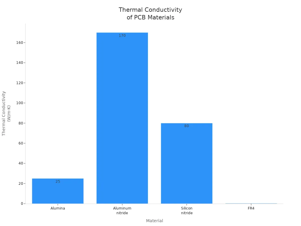
You can see the difference even more clearly in the chart below:

Ceramic PCBs often use substrates like aluminum nitride, which can reach thermal conductivity values between 170 and 220 W/(mK). Alumina substrates usually provide around 20 W/mK. In contrast, FR4 printed circuit boards have a thermal conductivity of only 0.25 to 0.4 W/(m·K) through the board and up to 1.0 W/(m·K) in-plane. This low value limits heat transfer and can cause heat to build up in your circuit.
Heat Dissipation
Heat dissipation is another area where ceramic pcb vs fr4 shows a clear winner. Ceramic printed circuit boards can handle much more heat because of their high thermal conductivity. For example, alumina PCBs offer 25–30 W/m·K, and aluminum nitride PCBs can reach 170 W/m·K or higher. FR4 boards, on the other hand, usually stay between 0.3 and 0.4 W/m·K.
Material | Thermal Conductivity (W/m·K) |
|---|---|
Alumina | 25–30 |
Aluminum nitride | 170 or higher |
Silicon nitride | 80–95 |
FR4 | 0.3–0.4 |
With ceramic PCBs, you get better heat dissipation, which helps prevent overheating in high-power applications. This is important for devices that generate a lot of heat, such as LED lighting, power modules, and RF systems. FR4 printed circuit boards often need extra insulation or cooling solutions to manage heat, which can add to the cost and complexity of your design.
Tip: If you want to improve heat transfer and avoid component failure, ceramic PCBs are the better choice for thermal management.
Reliability
Reliability is a key factor in the ceramic pcb vs fr4 debate. Ceramic printed circuit boards can operate at much higher temperatures, usually between 150°C and 250°C, and sometimes even higher. FR4 boards have a maximum operating temperature of about 130°C. When you use ceramic PCBs, you also benefit from superior thermal cycling endurance. This means the board can handle repeated heating and cooling without cracking or losing performance.
Type of PCB | Maximum Operating Temperature | Thermal Cycling Endurance |
|---|---|---|
Ceramic PCBs | 150-250°C | Superior |
FR-4 PCBs | Up to 130°C | Limited |
Ceramic PCBs keep their structure even at extreme temperatures, sometimes up to 800°C. Their low coefficient of thermal expansion (CTE) helps reduce mechanical stress during thermal cycling. This lowers the risk of solder joint failures and keeps your printed circuit boards working longer. You also get strong resistance to vibration, shock, and mechanical stress, which makes ceramic PCBs ideal for aerospace, automotive, and industrial uses. FR4 boards offer good mechanical strength for everyday electronics, but they do not match the performance of ceramic PCBs in harsh environments.
Ceramic PCB Features

Material Properties
You benefit from several unique material properties when you choose a ceramic pcb. These properties make it ideal for handling heat and maintaining performance in demanding environments.
High thermal conductivity, sometimes reaching up to 170 W/m·K, helps move heat away from sensitive components.
Excellent dielectric strength and electrical insulation keep circuits safe and efficient.
Low coefficient of thermal expansion (CTE) reduces stress during temperature changes.
High reliability in harsh environments, such as those with vibration or extreme temperatures.
Chemical stability and corrosion resistance ensure long-term durability.
Materials like aluminum nitride and alumina provide rapid heat dissipation, which is crucial for power amplifiers and high-frequency circuits.
Ceramic pcb materials also offer superior dielectric properties. This means you get reduced signal loss and better signal integrity, which is important for high-frequency and high-power applications. Lower dissipation factors help your circuits run more efficiently, especially in RF power amplifiers and high-speed digital systems.
Application Suitability
Ceramic pcb technology fits a wide range of industries that demand strong thermal management and reliability. You often see these boards in:
Industry | Application Scenario |
|---|---|
Satellite communication modules and avionics for extreme temperature stability. | |
Automotive Electronics | Battery management and motor control in electric vehicles, handling high temperatures. |
Industrial and Power Electronics | High-power inverters and motor drives, providing thermal management for large currents. |
Military and Defense | Missile guidance systems and ruggedized communication devices, performing under extreme conditions. |
LED Lighting and High-Power Semiconductors | High-power LEDs to manage heat and maintain performance efficiency. |
You can rely on ceramic pcb solutions for LED lighting, power modules, and automotive systems. These boards help extend LED lifespan, improve power module reliability, and support engine control units in vehicles.
LT CIRCUIT Solutions
LT CIRCUIT stands out as a leader in ceramic pcb technology. You gain access to advanced products that deliver superior heat dissipation and electrical insulation. LT CIRCUIT uses materials like aluminum oxide and silicon nitride to ensure excellent thermal management in high-power environments.
You find LT CIRCUIT ceramic pcbs in electric vehicles, power supplies, and industrial inverters. These boards handle large amounts of heat and current, making them perfect for demanding power applications. LT CIRCUIT’s ceramic pcbs also feature a black solder mask, which enhances heat dissipation. You can trust these solutions to perform reliably from -50°C to 150°C, even when your application faces tough conditions.
Note: LT CIRCUIT’s expertise in ceramic pcb manufacturing helps you achieve better performance and reliability in high-power and high-temperature applications.
FR4 PCB Features
Material Properties
You often choose fr4 for its balanced set of material properties. This material provides moderate thermal conductivity, which helps move heat away from components. The glass transition temperature (Tg) tells you how much heat the board can handle before it becomes flexible. Standard fr4 has a Tg around 130°C, but you can select high Tg options for tougher environments. The coefficient of thermal expansion (CTE) measures how much the board expands with heat. Low CTE helps prevent stress and cracking. Fr4 also resists moisture, so your circuits stay reliable even in humid places.
Property | Description |
|---|---|
Thermal Conductivity | 0.3 to 0.5 W/m·K aids in heat dissipation. |
Glass Transition Temperature | Tg around 130°C; high Tg materials (>170°C) for high-temp uses. |
Coefficient of Thermal Expansion | Controls expansion rates, prevents stress. |
Moisture Resistance | Low water absorption keeps performance stable. |
Cost Benefits
Fr4 stands out for its cost-effectiveness. You can produce high-performance boards at a low price, which is perfect for mass production. The average cost for fr4 pcb ranges from $1 to $10 per square foot, while ceramic boards cost much more. This affordability lets you use fr4 in many consumer electronics, such as smartphones, laptops, and LED lighting. Manufacturers prefer fr4 because it balances performance, reliability, and price.
Tip: Fr4 is ideal for large-scale projects where you need both quality and savings.
LT CIRCUIT Solutions
LT CIRCUIT offers a wide range of fr4 solutions for general electronics. You can choose boards for low, medium, or high-temperature environments. LT CIRCUIT ensures quality by following strict standards and testing, including thermal shock and X-ray inspections. You get reliable fr4 boards for everything from home appliances to advanced networking hardware. LT CIRCUIT’s expertise helps you find the right fr4 solution for your needs.
Choosing the Right PCB
Key Factors
You need to look at several important factors when choosing between ceramic and FR4 PCBs. The table below helps you compare the main differences:
Factor | Ceramic PCBs | FR4 PCBs |
|---|---|---|
Thermal Conductivity | Superior for high-power applications | Good, but less efficient in heat dissipation |
Electrical Performance | Excellent insulation, low dielectric losses | Good for many frequencies |
Design Flexibility | Fewer layers, higher cost | Flexible for complex, multilayer designs |
Environmental Impact | More eco-friendly and recyclable | Recyclable, but epoxy resin can be a challenge |
Mechanical Strength | Highly durable, resists stress and vibration | Good strength, less robust in extremes |
Cost | More expensive, best for high-performance | Cost-effective for large-scale production |
Manufacturing Lead Time | Longer, more complex processes | Shorter, well-established processes |
You should also think about your budget and reliability needs. If your project demands high reliability, a higher upfront cost for ceramic PCBs may save you money in the long run by reducing repairs. Material compatibility with manufacturing processes helps prevent defects. For demanding applications, ceramic PCBs excel. For less critical projects, FR4 offers a smart balance of cost and performance.
Tip: Consider how your chosen material will perform over the product’s lifecycle, especially under thermal cycling, mechanical stress, and environmental factors.
Application Examples
Ceramic PCBs work best in high-power and high-temperature environments. You see them in LED lighting, where alumina ceramic PCBs provide 20–30 W/mK thermal conductivity and help LEDs last 30% longer than FR4 boards. Aerospace electronics often use aluminum nitride ceramic PCBs for their 170 W/mK thermal conductivity and durability under vibration.
FR4 PCBs are popular in everyday consumer electronics. You find them in smartphones, PCs, motherboards, and power management circuits. These devices benefit from FR4’s cost-effectiveness and design flexibility.
If you need help choosing the right PCB for your project, you can consult LT CIRCUIT. Their experts offer customized solutions to match your thermal management, budget, and reliability requirements.
Ceramic PCBs give you superior thermal management in high-power, high-temperature, and harsh environments. FR4 PCBs offer cost savings and flexibility for general electronics.
Feature | FR4 PCB | |
|---|---|---|
Thermal Management | Excellent | Moderate |
Cost | High | Low |
Application | Specialized | General |
You can trust LT CIRCUIT for expert guidance and custom PCB solutions. Always consider your needs and consult professionals before choosing.
FAQ
What makes ceramic PCBs better for heat management?
You get much higher thermal conductivity with ceramic PCBs. This helps your devices stay cool and work longer, especially in high-power or high-temperature situations.
Can you use FR4 PCBs in high-power devices?
You should avoid FR4 for high-power devices. FR4 does not move heat well. Your components may overheat and fail faster.
How do you choose the right PCB for your project?
You should look at your device’s heat needs, budget, and reliability. For expert advice, contact LT CIRCUIT for a custom solution.
Tip: Always match your PCB material to your application’s power and temperature demands.
See Also
The Advantages of Ceramic PCBs for Heat Management
High TG FR4 PCBs: Optimal Performance in Harsh Conditions
Choosing Between Aluminum and FR4 PCBs for Designs
Choosing PCB Materials for Effective Communication Devices
Investigating Thermal and Electrical Performance of Aluminum PCBs