Designing Reliable Rigid-Flex PCBs for Automotive Electronics

Reliable rigid-flex PCBs help make car electronics small and strong. Cars can get hotter than 125°C, shake a lot, and parts can wear out. Rules like AEC-Q100 and ISO 16750 say tests must check shaking, heating, and how long things last. Picking the right materials and making a strong design keeps things safe and working for a long time.
Key Takeaways
Pick tough materials like polyimide and FR-4 for rigid-flex PCBs. These materials help the boards handle heat and shaking in cars.
Make sure to design boards with the right bend radius. Use smooth routing and fewer connectors. This helps stop breaks and lowers mistakes when putting them together.
Test the PCBs a lot with heat, shaking, and electrical checks. This makes sure they last long and work well in hard car conditions.
Automotive Demands
Temperature and Vibration
Car electronics must handle big temperature changes and lots of shaking. Rigid-flex PCBs work from −40 °C up to 125 °C. These tough conditions can change how the PCB moves. Its natural frequency drops from 328 Hz to 313 Hz as it gets hotter. Engineers check things like Young’s modulus and thermal expansion at different temperatures. This helps them guess how the board will act. Tests show that 68% of QFN terminal pads can crack after 50 cycles. This means strong design is very important. Making the PCB thicker by 66% can help solder joints last longer. But this does not help as much when it gets hotter. These results prove that picking good materials and smart design are needed for safety.
Parameter/Aspect | Quantitative Finding/Result | Description/Context |
|---|---|---|
Temperature range tested | −40 °C to 125 °C | Typical automotive thermal cycling range |
PCB first natural frequency shift | 328 Hz to 313 Hz | Frequency drops as temperature rises |
Cracking in QFN terminal pads | 68% after 50 cycles | Shows degradation from combined thermal and vibration loading |
Fatigue life improvement by thickness | 66.7% at 24 °C, 66.5% at 60 °C | Thicker boards last longer under stress |
Space and Weight Constraints
Today’s cars need small and light electronics. Rigid-flex PCBs help fit more parts in less space. Engineers use curved traces and meander shapes to spread out stress. This keeps weak spots from forming. They also use stronger metal layers and more layers in the board. These tricks make the board last longer. Designers can save space and cut weight without losing strength.
Instrument clusters use flex and rigid-flex PCBs to handle shaking and heat.
Curved traces and spreading out stress stop breaks.
Using more layers helps the board work better in tight spots.
Safety and Compliance
Safety is always most important in car electronics. Rules like ISO 26262 and ASIL help engineers check risks and test their work. Groups like AEC set tough rules for parts. Safety groups like FMVSS in the US and Euro NCAP in Europe make sure car electronics meet safety rules. Engineers use FMEA and worst-case checks to find and stop problems. This makes sure rigid-flex PCBs are safe and work well.
Standard/Study Name | Description | Role in Automotive Electronics Safety and Compliance |
|---|---|---|
ISO 26262 | Functional safety standard for road vehicles | Provides framework for risk analysis and validation |
ASIL | Risk classification scheme | Guides allowable failure rates and safety integrity levels |
AEC-Q | Qualification standards for electronic components | Ensures component reliability |
FMVSS | US safety performance standards | Mandates minimum safety thresholds for vehicle electronics |
FMEA | Failure analysis method | Helps prevent electronic failures |
Reliable Rigid-Flex PCBs: Key Features

Material Choices
Picking the right materials is very important for reliable rigid-flex PCBs. Polyimide is used for flexible layers because it bends well and does not melt easily. FR-4 is used for rigid parts because it is strong and keeps its shape. These materials help the board work in hot and shaky cars. Engineers test how strong the board is by bending it and flexing it many times. They also use tests to see if the board can handle fast temperature changes. If the board cracks or peels, it fails the test. Peel strength tests check if copper stays stuck to the board. If copper sticks well, the board lasts longer. IPC-6013 and IPC-TM-650 are rules that tell engineers how to do these tests. When engineers follow these rules, the board stays safe and strong for a long time.
Tip: Using polyimide and FR-4 helps reliable rigid-flex PCBs stand up to heat and shaking in cars.
Stackup and Routing
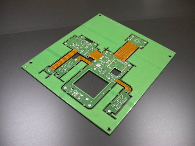
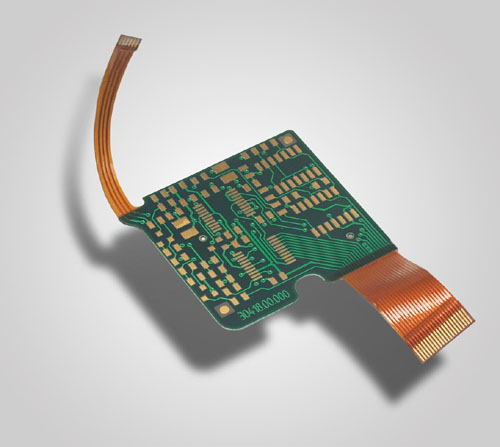
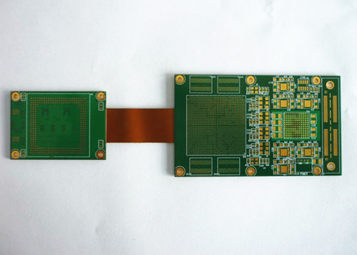
How the layers are put together is called the stackup. Stackup and routing are important for reliable rigid-flex PCBs. Engineers mix rigid and flexible layers to fit small spaces in cars. Flexible layers can bend and twist to fit inside dashboards or sensors. This design means fewer connectors and cables are needed. Reports show that using both rigid and flexible parts helps make car electronics smaller and lighter. Flexible circuits can fold to fit into tiny or odd shapes. Engineers use computers to plan how to bend the board safely. These plans help stop sharp bends and control how the board curves. Good routing spreads out the lines and keeps stress away from weak spots. This helps the board keep working when the car shakes or gets hot.
Stackup Feature | Benefit in Automotive Use |
|---|---|
Rigid-Flex Combination | Saves space and weight |
Flexible Layers | Fit into tight or curved spaces |
Fewer Connectors | Reduces failure points |
Optimized Routing | Prevents stress and breakage |
Assembly Error Reduction
Reliable rigid-flex PCBs help stop mistakes when putting car electronics together. These boards have both rigid and flexible parts, so they need fewer connectors and solder joints. Fewer connections mean there are fewer places for problems to happen. More than 28% of all rigid-flex PCBs are used in cars. The dynamic flex part, which helps with shaking, is over 60% of the market. FR-4 is strong and is used in about one third of boards. Flex circuits only fit one way, so workers cannot put them in wrong. This simple design makes testing and fixing faster and easier. With fewer connectors and just one board, assembly is quicker and more reliable. These things help car makers build safer and longer-lasting electronics.
Using both rigid and flexible layers means fewer connectors are needed.
Fewer solder joints lower the chance of problems when cars shake.
Flex circuits only fit one way, so mistakes are less likely.
Simple assembly saves time and money.
Note: Reliable rigid-flex PCBs make boards easier to put together and help stop mistakes.
Design Guidelines
Bend Radius and Flex Areas
Engineers must watch the bend radius in flex areas. The IPC 2223 standard gives rules for the smallest bend radius. This depends on how many layers and how thick the material is. For single-layer flex circuits, the bend radius should be about six times the flex thickness. Two-layer designs need at least twelve times the thickness. Multi-layer circuits need up to twenty-four times the thickness. These rules help stop copper from cracking or peeling off.
Designers should not use sharp angles in trace routing. Curved traces help spread out stress and lower the chance of copper getting thin. Using thinner materials lets the board bend more, but engineers still need to follow the minimum bend radius. Adhesive-less materials and thinner copper or polyimide layers make the board more flexible and tough. In dynamic flex applications, bigger bend radii are needed for lots of bending. If IPC standards do not cover a special case, engineers build test boards and check them in the lab.
Tip: Never put components, vias, or solder joints in bend zones. This helps stop the board from breaking when it bends a lot.
Via and Pad Placement
Good via and pad placement helps the board last longer. Engineers should keep plated through holes at least 20 mil away from any bend area. This space helps lower stress on the copper and stops cracks. Conductors smaller than 10 mil should be in the neutral bend axis. This is where there is the least pulling or pushing.
Designers should not use sharp 90° bends in traces. Gentle curves keep the copper safe from damage. Teardrop-shaped pads and rounded corners make the board stronger and help stop cracks. Tear guards along the inside bend radius can stop the flex material from tearing. There should be at least 10 mil between flex regions to stop stress from building up.
Put vias and pads outside bend areas.
Use teardrop-shaped vias for more strength.
Keep the right space between drill holes and copper.
Transition Zones
Transition zones join rigid and flexible parts. These spots get a lot of stress. Engineers must make smooth changes without sudden steps in thickness or shape. Cross-hatch patterns on ground and power planes cut down copper and make these zones more flexible.
Adhesive-less flex materials work well in transition zones. They bend better, keep out water, and handle heat. Designers should not put parts or thick copper near the transition. Planning bends and trace paths helps the board stay strong and flexible.
Note: Modeling and simulation before layout can show stress points in transition zones. This lets engineers fix the design before making the board.
Stiffeners and Strain Relief
Stiffeners and strain relief help stop the board from breaking. Engineers use Kapton or FR-4 stiffeners to support spots where parts are mounted on flex sections. These stiffeners keep the board flat and steady during use.
Tests show that strain relief makes flexible circuits stiffer and stronger. For example, testing with 3,000 cycles per day made the board stiffer and able to handle more force. But not all stiffening works the same. Some scaffold stiffening can make repairs weaker. Engineers must pick the right stiffener for each job.
Property Type | Effect of Strain Relief (Mechanical Stimulation) | Effect of Scaffold Stiffening (ADHT Crosslinking) |
|---|---|---|
Linear stiffness | Increased a lot | Lower repair stiffness in real use |
Maximum force | Higher with strain relief | Lowered maximum force in repair tissue |
Strain energy | Better with strain relief | Did not get better, sometimes got worse |
Linear modulus | Improved with strain relief | Got worse in repair tissue |
Maximum stress | Higher with strain relief | Lower in real use |
Reliable Rigid-Flex PCBs work better with good stiffeners and strain relief. These features help the board survive shaking, bending, and lots of use in cars.
Manufacturing and Testing

Quality Control
Making rigid-flex PCBs for cars needs careful checks. Workers look at each board to find mistakes. They use their eyes and X-rays to spot problems on the surface and inside. AOI machines scan boards for missing parts or bad solder. ICT makes sure every part works and is in the right spot. Functional tests copy real car use to see if the board works well.
Test Type | Purpose/What is Inspected | Criteria/Outcome |
|---|---|---|
Finds problems on the outside and inside, like bad solder | Pass or fail | |
Peel Test | Checks how well layers stick together | Pass or fail, plus a number |
Solder Pot and Float Tests | Tests if solder sticks and if the board handles heat | Pass or fail |
AOI | Looks for mistakes like not enough solder or broken joints | Pass or fail |
Continuity Test | Checks for open or short circuits in empty boards | Pass or fail |
AOI and X-ray checks help find problems early. This saves money and helps make more good boards.
Moisture and Pre-Bake
Water can make PCBs break or stop working. Makers bake boards before putting them together. Workers put boards in ovens at set heat. Baking dries the boards and stops bubbles or cracks when soldering. It also helps layers stick and keeps boards strong when hot. Workers check water levels and change bake time for each group.
Baking gets rid of water in the board.
Dry boards do not crack or fall apart.
Baking the right way helps boards work better.
Reliability Testing
Car PCBs must pass hard tests to prove they last. Engineers heat and cool boards to see if they survive big changes. They shake and hit boards to copy what happens in cars. Chemical tests put boards in acids and bases. Electrical tests check if signals and power work right. Every board must meet IPC-A-610 Class 3 rules for strong electronics.
Testing Method | Purpose | Outcome Criteria for Automotive Durability |
|---|---|---|
Heats and cools boards to find cracks or damage | No breaks or failures after many cycles | |
Mechanical Stress Tests | Shakes and hits boards to copy car bumps and shakes | Board stays strong and keeps working |
Electrical Performance Testing | Checks if signals and power are good during use | All numbers stay in the safe range |
Passing these tests shows the PCB will work well in tough car conditions.
Common Pitfalls
Material Incompatibility
Material incompatibility can make rigid-flex PCBs fail early. Sometimes, engineers pick materials that expand at different rates. This causes stress when the board heats up or cools down. Polyimide and FR-4 do not expand the same way. When the board gets hot, solder joints and vias might crack. Buried holes are usually the first to break from heat. Thicker plating and bigger holes help a little, but picking the wrong material still makes the board weak. If the board soaks up water, it can start to peel apart. Using protective coatings and picking the right materials helps stop these problems.
Tip: Always use materials with similar thermal properties to stop cracks and peeling.
Mechanical Stress
Cars put a lot of stress on electronics. Vibration and shock can break solder joints and vias. Shaker tables copy the shaking that happens in real cars. These tests show where the board is weak. Fast changes in temperature make things worse. Solder joints can get hard and break, and vias can crack. Looking inside the board often shows cracks and broken solder after stress tests. Standards like IPC-TM-650 and JEDEC JESD22 tell how to do these tests.
Vibration finds weak spots in solder joints and vias.
Heating and cooling from -40°C to +125°C causes cracks.
Water and fast temperature changes can bend parts.
Process Variations
Small changes in how boards are made can make them less reliable. Changing the number of layers, thickness, or hole size can change how the board works. Studies show that the number of layers matters most for reliability. The thickness of the board and the size of the holes also matter. For example, a 0.4 mm hole and 100 μm thick board last longer.
Factor | Key Finding on Reliability Impact |
|---|---|
Number of layers | |
Laminate thickness | Optimal at 100 μm |
Plated hole diameter | Optimal at 0.4 mm |
Laminate type | Polyimide preferred |
Current density | Second most significant factor |
Monte Carlo simulations help engineers guess how changes and aging affect the board. Using real car use cases gives better results than only testing the worst case.
Designers make Reliable Rigid-Flex PCBs work well by picking strong materials. They add stiffeners to help the board stay flat and strong. They also plan where the board will bend so it does not break. Quality control checks make sure the boards are made right. Environmental tests check if the boards can handle heat, water, and chemicals. Doing all these things helps the boards last a long time in cars and work well.
FAQ
What makes rigid-flex PCBs better for cars than standard PCBs?
Rigid-flex PCBs are strong and can bend. They fit into small spaces in cars. They need fewer connectors than regular boards. They also handle shaking better than standard boards.
How do engineers test rigid-flex PCBs for automotive use?
Engineers heat and cool the boards many times. They shake the boards to see if they break. They run electricity through them to check if they work. These tests show if the board can last in cars.
Can rigid-flex PCBs lower assembly mistakes in automotive electronics?
Yes. These boards use fewer connectors and are made in one piece. This helps workers put them together faster. It also means there are fewer chances for mistakes.
See Also
Industrial And Medical Uses Of Rigid Flex PCBs Explained
Top Benefits Of Rigid Flex PCBs In Tight Electronic Spaces
A Comprehensive Guide To Rigid Flex PCB Design And Structure
Choosing Between Flex And Rigid PCBs For Electronics Projects
Materials And Processes In Rigid PCB Manufacturing For Industry
