Design Considerations for FR4 Polyimide Rigid-Flexible PCBs in Medical Device Applications
You must follow strict rules when making rigid-flexible pcbs for medical devices. These medical uses need you to pick the right materials, make sure the boards work very well, and follow all the rules.
LT CIRCUIT gives you advanced PCB solutions for strong, high-quality medical technology.
Design Consideration | Numerical Value / Statistic |
|---|---|
Inside ring is at least 1 mil; outside ring is at least 2 mils | |
Minimum Dielectric Thickness | 3.5 mils |
Conductor Junction Size | At least 20% of the smallest trace width or 2 mils |
Barrel Fill for Through-Hole | 75% filled, no empty spots allowed |
Surface Mount Device Size | As small as 0.25 mm by 0.125 mm |
Lab-on-PCB systems show how new rigid-flexible pcbs help medical devices work better. These new ideas help you keep up with changing medical device needs by making sure they are good, work well, and are safe.
Key Takeaways
Use polyimide for the flexible parts. Use FR4 for the hard parts. This helps balance strength, flexibility, and safety in medical PCBs.
Follow strict rules for bend radius and layers. This keeps your rigid-flex PCB strong. It also helps it work well in medical devices.
Test each board very carefully. Keep full records of every test. This helps meet medical safety rules. It also makes sure the device works well.
Rigid-Flexible PCBs in Medical Devices
Benefits and Applications
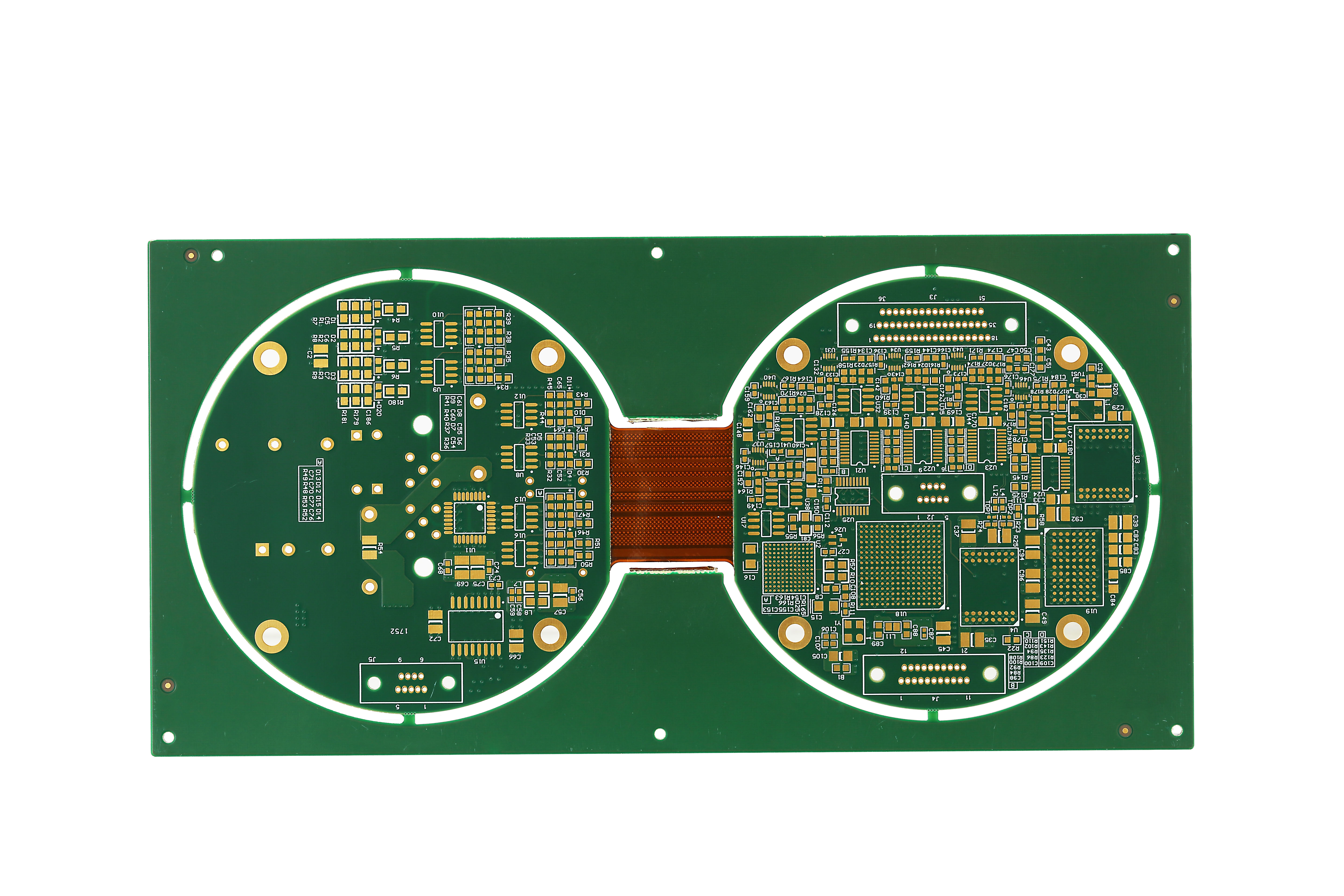
Rigid-flexible pcbs help make medical devices better. They mix the good parts of rigid and flexible pcb technology. These pcbs let you build small, light, and strong medical electronics. You can use rigid flex pcb in many things. Some examples are pacemakers, patient monitors, digital imaging, and health trackers.
Benefits and Applications of Rigid-Flex PCBs in Healthcare | |
|---|---|
Hearing Aids | Small circuits fit inside tiny spaces. They bend and move with your jaw. |
Pacemakers and Implantable Devices | The circuits last long and work well in the body. They are safe and can bend. |
Patient Monitoring Systems | These pcbs help connect sensors and recorders. They bend with the body and work better. |
Digital Imaging Systems | They carry signals from detectors. They fit in small spaces and bend with moving arms. |
Endoscopes and Catheters | Thin, bendy circuits help steer and protect fiber optic links. |
Robotic Surgery Devices | They send signals and power through moving parts in small surgical tools. |
These uses are very important for new medical devices. Rigid flex pcb designs help meet tough rules for being small, strong, and flexible.
Why Choose Rigid Flex PCBs
Rigid flex pcb technology gives special benefits for medical devices. These pcbs use fewer solder joints and connectors. This makes them more reliable and less likely to break. Rigid flex pcb has hard parts for strength and bendy parts for movement. This makes them last longer in small and moving devices.
Rigid flex pcb puts many pcbs together in one piece. This means you do not need extra connectors or cables. Medical devices can be smaller and save space.
Rigid-flex pcb helps signals stay clear. Fewer connections mean less noise and less interference.
Polyimide adhesives in flexible pcb materials handle heat and keep the board strong. This is important for medical use.
Rigid flex pcb follows rules like IPC-6013 and IPC-2223. This means they work well when bent or heated.
Rigid-flexible pcbs are best when you need small size, strength, and trust that they will work.
You use rigid flex pcb for wearable medical devices and implants. They are also good for patient monitors. These jobs need flexible pcb and strong, steady performance. Rigid-flex pcb technology helps you make new and better medical devices.
Material Design Considerations
FR4 and Polyimide Properties
When you make rigid flex pcb for medical devices, you need to pick the right materials. FR4 and polyimide are the main choices for these special circuit boards. Each one has its own strengths for your design.
Polyimide is very bendy, can handle high heat, and is strong. You use polyimide in flexible pcb layers that need to move or twist. Polyimide works in very hot or cold places, from -200°C to 300°C. It keeps its shape and strength even when things get tough. This makes polyimide great for medical uses where you need it to last and bend.
FR4 is a top pick for the hard parts of rigid flex pcb. It gives good electrical insulation, some flexibility, and saves money. FR4 works best in parts of your pcb that do not bend. You can count on FR4 for its solid dielectric properties and chemical resistance.
Here is a table that compares the main properties:
Property | FR4 | Polyimide (Kapton HN, Isola P95) |
|---|---|---|
Tensile Strength | ~70 MPa | 231 MPa at 23°C; 139 MPa at 200°C |
Flexibility | Rigid | Highly flexible |
Thermal Stability Range | -50°C to 110°C | -200°C to 300°C |
Dielectric Constant (Dk) | 2.78 to 3.48 at 1 GHz | 3.4 at 1 kHz; 3.78 at 1 GHz |
Chemical Resistance | Good | Better |
Moisture Absorption | Low | Very low |
Price | Low-priced | High-priced |
You can see polyimide is much more flexible and can take more heat than FR4. Polyimide also fights off chemicals better and does not soak up much water. These things help your rigid flex pcb work well in tough medical places.
You should think about how thick your materials are. Polyimide can be thinner than 100 µm but still stays strong and bendy. This lets you make very thin flexible pcb layers for small medical devices.
LT CIRCUIT helps you use advanced materials in your projects. You get fast HDI pcb making, so you get your boards quicker and with smaller spaces between lines. LT CIRCUIT checks boards with special cameras and X-rays to catch over 99.98% of problems. You get rigid flex pcb that meets IPC Class 3 rules for important medical jobs. Their way of working cuts down on wasted materials by 15% and lowers fixing costs by 60%. You can trust LT CIRCUIT to give you strong, high-quality medical circuit boards.
Biocompatibility and Safety
You must make sure every material in your rigid flex pcb is safe for the body. Medical devices need pcbs that do not hurt people or cause bad reactions. Polyimide and FR4 both help meet these safety needs.
Polyimide is bendy and safe for the body. You can use polyimide in implants that move with the body. Polyimide does not react with chemicals and is not toxic, so it is safe for medical pcb designs. FR4 types like Isola 370hr and FR408HR have high CTI values. This means they are safe and work well for medical circuit boards.
You need to follow world rules to make sure your pcb is safe. Here is a table of important rules and what they do:
Standard/Certification | Description | Relevance to Biocompatibility and Safety |
|---|---|---|
Biological evaluation of medical devices | Checks that materials do not cause bad reactions in the body | |
USP Class VI | Biocompatibility standards for plastics | Makes sure plastics are safe for medical use |
ASTM F1980 | Accelerated aging testing | Proves materials last and stay strong in the body |
FDA 21 CFR Part 820 | Quality System Regulation | Makes sure boards are made safely and with good quality |
Medical Applications Addendum to IPC-6012E | Makes sure medical PCBs are very reliable and do not fail | |
ISO 13485 | Certification for manufacturing, design, and distribution of medical devices | Requires records and checks for quality in medical PCB making |
IEC 60601-1 | Safety standard for medical devices that contact patients or monitor vitals | Sets safe limits for electricity and heat in medical devices |
You should use special coatings like parylene to make your flexible pcb even safer. Parylene makes a thin cover that keeps out water and chemicals. This extra layer helps your rigid flex pcb last longer and stay safe in medical places.
LT CIRCUIT helps you follow all the rules with full records of materials and steps. You get rigid flex pcb that meets ISO 9001, ISO 13485, and UL rules. LT CIRCUIT uses smart checks like AOI, X-ray, and flying probe tests. These checks make sure your medical pcb is very safe and high quality. You can count on LT CIRCUIT for medical circuit boards that are both bendy and safe.
Tip: Always check that your polyimide and FR4 materials meet the newest medical rules before you finish your design. This step keeps patients safe and helps you get approval.
You must balance bendiness, strength, and safety in every rigid flex pcb for medical use. Polyimide gives you the bendiness and safety you need. FR4 gives you strength and keeps electricity safe. LT CIRCUIT’s skill with materials and quality checks helps you get the best results for your medical devices.
Rigid Flex PCB Stackup and Layout
Layer Configuration
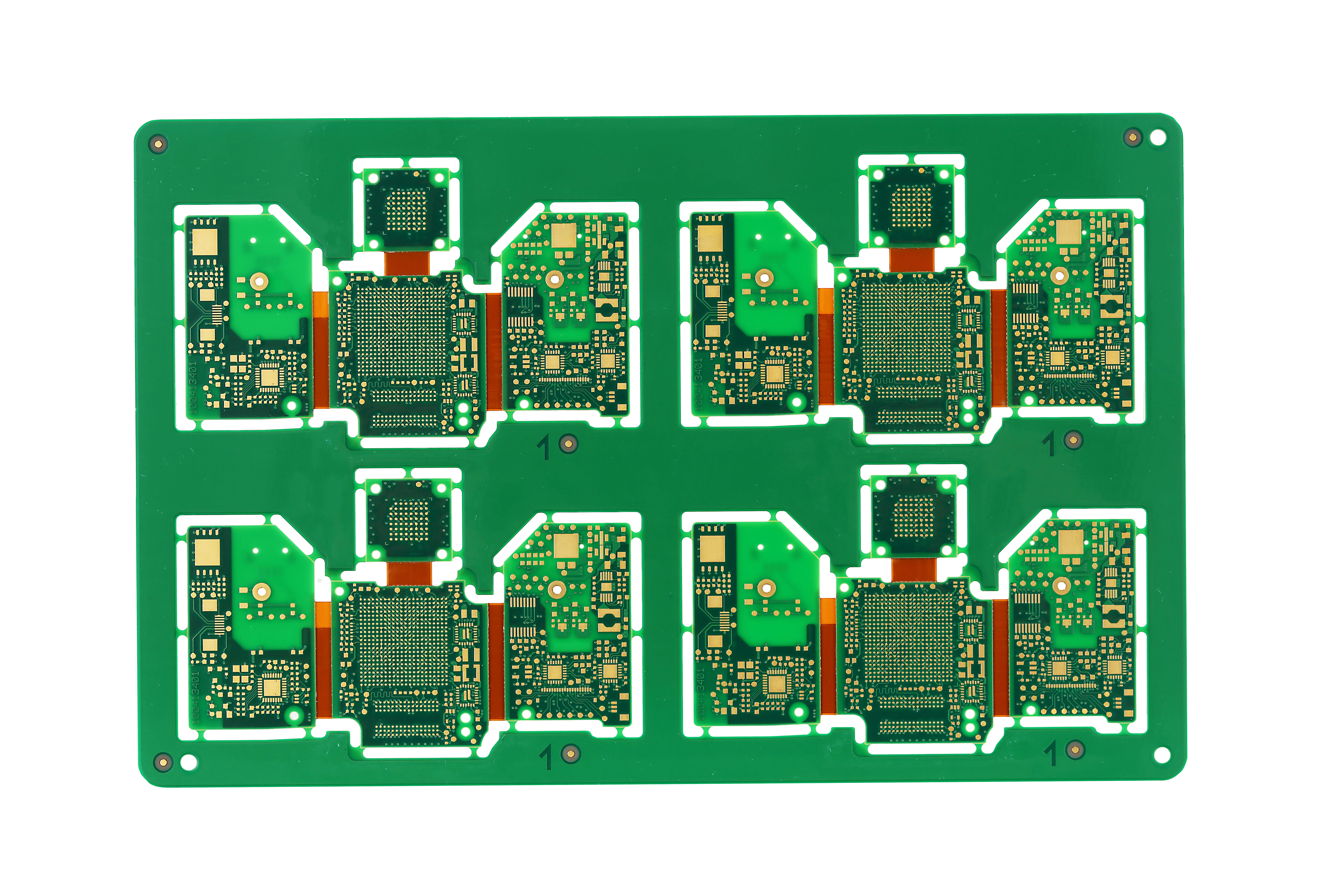
You have to plan your rigid flex pcb stackup carefully. Picking the right layers helps you get good electrical work, strength, and flexibility. In rigid flex pcb, FR4 is for hard parts and polyimide is for flexible pcb parts. If your board needs to bend a lot, use only two layers. If it bends just a little, you can use up to 20 layers. This way, your rigid flex circuit stays strong and works well.
Design Aspect | Specification / Recommendation |
|---|---|
Number of Layers (Dynamic Bend) | |
Number of Layers (Stable Bend) | Up to 10 to 20 layers |
Bend Radius (Dynamic Bend) | At least 100 times the material thickness |
Bend Radius (Stable Bend) | About 10 times the material thickness |
Materials | Rigid: FR-4; Flex: Polyimide |
Plated Through Holes | Avoid in bending areas; use anchors and teardrops if needed |
Ground Plane in Flex Areas | Use cross-hatched ground planes |
You can use design tools like OrCAD X to set up stackups for each rigid and flexible pcb part. This helps you pick the right number of layers and materials for every section of your rigid flex pcb.
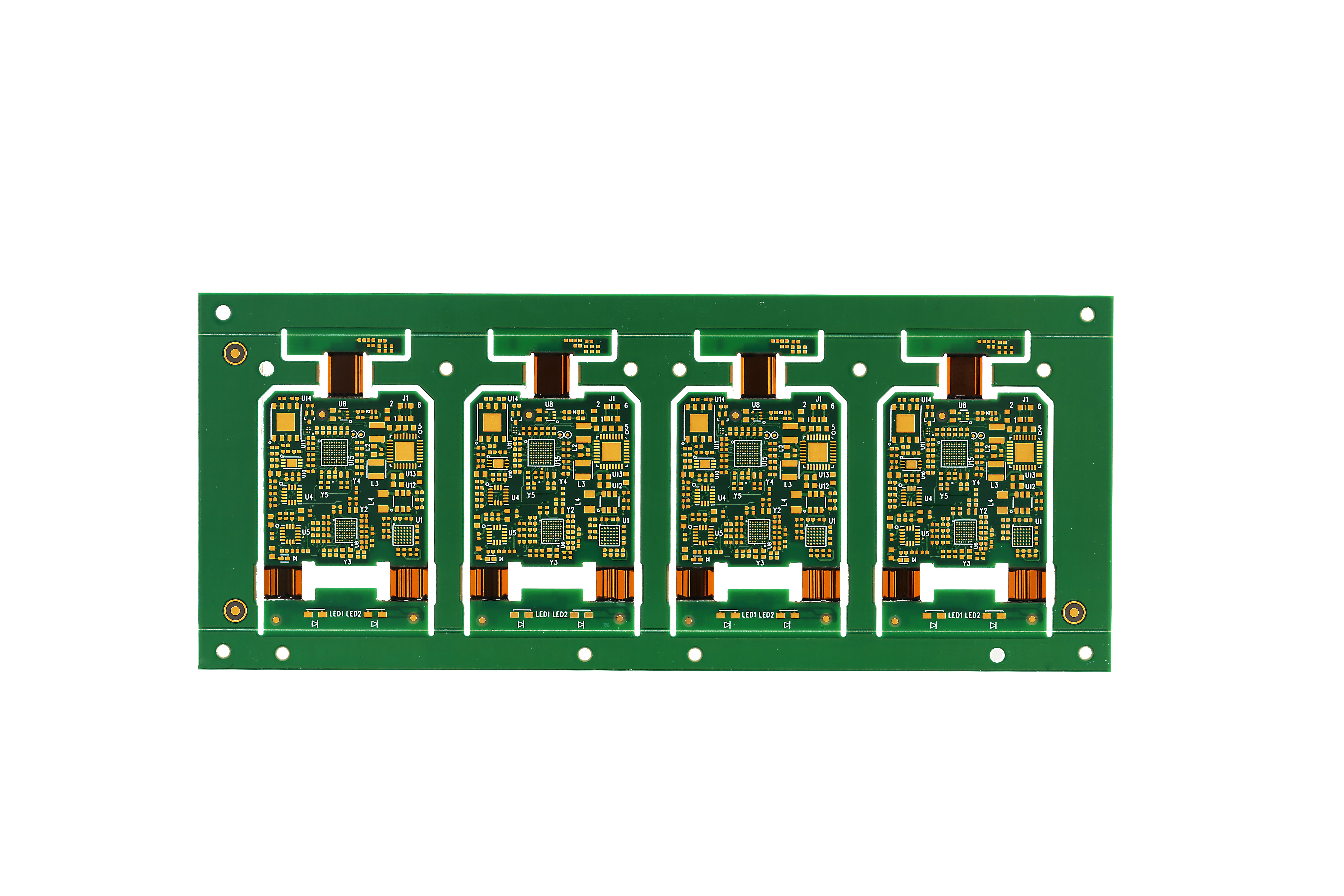
Rigid-to-Flex Transition
The spot where rigid and flexible pcb meet is very important. You need to match how much FR4 and polyimide grow with heat. This stops the layers from coming apart. Add stiffeners or glue at the transition to make it stronger. This keeps your rigid flex circuit from cracking or breaking.
Make the bend radius at least 10 times the flexible layer’s thickness.
Put in stiffeners or supports to help it last longer.
Talk to your board maker early about trace width, spacing, and layers.
You should build a test version of your rigid flex circuit before making a lot. Glue the rigid and flexible layers with special adhesives. Drill slowly in flexible pcb areas to keep them safe. These steps help you make a strong and steady rigid flex pcb.
Bend Radius and Flexibility
Flexibility is very important in rigid flex pcb design. You must follow bend radius rules so the board does not break. For one conductive layer, use a bend radius of at least 5 mm. For two layers, use at least 7 mm. If you need a 180-degree bend, use two 90-degree bends instead. This makes the board last longer.
Conductive Layers | Standard Minimum Radius | Advanced Minimum Radius |
|---|---|---|
1 layer | 5 mm | 3 mm |
2 layers | 7 mm | 5 mm |
You can figure out the smallest bend length with this formula:
G = (π × R × A2 / 180) + 4 mm
Here, R is the inside bend radius and A2 is the bend angle.
Use thin FR4 cores and fewer copper layers in the bend area. Add copper fill to spread out the stress. Always bend in the same direction as the glass fiber for best results. If you bend less than 10 times, use flexible soldermask. If you bend more, use coverlay for extra strength.
Tip: Always check your rigid flex circuit design with tests and flexibility checks before making many boards. This makes sure your rigid flex pcb will work the way you want.
Reliability and Performance
Mechanical Strength
You want your rigid flex pcbs to work for a long time. Medical devices can bend, twist, or move a lot. Mechanical strength is very important in these cases. The flexible pcb parts let the board bend many times without breaking. Flex cycle testing bends the board over and over to see if it lasts. X-ray and microsection analysis let you look inside the pcb. These tests show if the holes and layers stay strong. Rigid-flex pcb is stronger than just rigid or just flexible pcb. This means your medical pcb can handle drops, shocks, and shaking. You can trust your rigid-flex circuit to keep working in real medical devices.
Flex cycle testing shows how many bends your rigid flex pcb can take.
X-ray and microsection analysis check if the layers and holes are still good.
These tests prove that rigid flex pcbs are strong and reliable for medical boards.
Signal Integrity
Signal integrity means your signals move fast and clear through the pcb. You want your rigid-flex pcb to send signals without problems. Electrical tests check if the signals are steady and good. Controlled impedance routing helps keep signals from changing. Shielding and careful trace layout help stop noise and crosstalk. EMI reduction keeps outside signals from messing up your device. Signal integrity analysis during design and testing finds problems early. This helps your medical pcb work well in any situation.
Electrical tests check if your rigid flex pcb has good signals.
Controlled impedance routing and shielding keep signals safe.
EMI reduction and crosstalk control stop noise from hurting your device.
Signal integrity analysis helps you find problems before they get worse.
Tip: Always test your rigid-flex pcb for strength and signal quality. This makes sure your design is safe for medical devices.
Compliance and Standards
Medical Device Regulations
You have to follow special rules when making rigid-flexible pcbs for medical devices. These rules help keep patients safe and make sure devices work right. Some big groups make these rules for quality and safety in medicine.
IPC standards like IPC-A-600, IPC-2221, IPC-2581, and IPC-7351 tell you how to check boards, design them, share data, and set up surface parts.
ISO 13485 is a rule for making sure medical devices are made with good quality.
IEC 60601-1 is about safety and how well medical electrical equipment works.
IEC 62304 is for software steps in medical device programs.
You need to write down every step, like checking designs and looking for risks. These rules say you must keep records, watch for changes, and study problems that happen. LT CIRCUIT follows these world rules to help you meet the law for medical devices.
Note: Following these rules helps stop mistakes, makes devices work together, and helps you sell your medical products in more places.
Testing and Documentation
Testing and paperwork show your rigid-flexible pcbs meet medical rules. You must check each board for how it works, how strong it is, and how it looks. Good paperwork helps you track boards and pass checks.
Netlist files show how parts connect for tests after making the board.
Test plans give easy steps for each test.
Rule papers (RoHS, REACH, IPC) show you follow the law.
Electrical tests look for open or short circuits and check impedance.
Physical tests check how much the board can bend, flex, or peel.
Optical and X-ray checks find problems you can see or cannot see.
Working and environment tests show your board works in real medical places.
LT CIRCUIT uses smart tools to check boards and keeps good records for every group of boards. You get full test papers, proof you followed the rules, and files with details. This way, your medical devices stay safe, work well, and are ready to be sold.
Manufacturing Challenges and Solutions
Mechanical Stress
When you design rigid flex pcb for medical devices, you face many problems. One big problem is mechanical stress. Bending, twisting, and moving the board again and again can hurt the flexible pcb parts. You need to test your rigid-flex pcb by bending it, shaking it, and pulling on it. These tests show if your pcb can work in real life. Thermal shock testing checks if your rigid flex pcb can handle fast temperature changes. You also use IPC-6013 standards to test how flexible it is, how strong the peel is, and how well it handles hot and cold. Doing these things helps you make sure your rigid flex pcb stays strong and works well.
Challenge | Empirical Solution / Best Practice |
|---|---|
Follow minimum bend radii to prevent mechanical failure and signal issues | |
Mechanical reliability | Use anchors, teardrops, and avoid sharp angles to increase trace durability under flexing |
Avoid vias in flex areas; route traces perpendicular to bend lines | |
Trace lifting | Increase trace surface area to improve adhesion and reduce mechanical stress |
Tip: Always figure out the right bend radius for your flexible pcb layers. This step helps you stop cracks and breaks.
Manufacturability
You want your rigid flex pcb to be simple to make and put together. Good manufacturability starts with smart design choices. Put all SMT parts on one side and PTH parts on the top. This makes building the board faster and helps stop mistakes. Use thermal relief patterns for vias and add teardrops where traces meet pads. These things lower stress from heat and bending. Always check your design with electrical rules check and design rules check. Make sure you have all your files ready in formats like Gerber or IPC-2581. Talking clearly with your manufacturer helps you avoid waiting.
Here are some best practices:
Put similar parts in the same direction for easy soldering.
Do not put parts behind PTH parts.
Add test points for all important signals.
Use high-density layouts to fit odd shapes in medical devices.
Pick thinner copper and base materials for better bending.
LT CIRCUIT Solutions
LT CIRCUIT helps you fix hard problems when making rigid flex pcb. For example, in a brain surgery implant project, LT CIRCUIT used platinum-cured silicone overmolding and 3D X-ray checks. This made sure the device was sealed tight and the vias were filled right. The result was a device that got FDA approval for deep brain stimulation. LT CIRCUIT also uses new process controls, like laser-drilled microvias and stacking layers one by one, to make high-density and high-frequency rigid-flex pcb designs. You get rigid flex pcbs that meet tough medical rules and work very well.
LT CIRCUIT’s quality checks find over 99.98% of problems.
Their team helps you make your board more flexible and strong.
You get full paperwork and help for every rigid flex pcb project.
Note: LT CIRCUIT’s skill with rigid-flexible pcbs helps you make safe, reliable medical devices faster.
When you make pcb for medical devices, you must think about design, picking the right materials, and following the rules. Medical devices need to work well all the time. LT CIRCUIT helps you reach your design goals for these devices. Their pcb solutions are good for new and advanced medical uses. Keep learning and talk to experts so you can follow new medical device rules.
FAQ
What makes rigid-flexible pcbs ideal for medical devices?
These boards are strong and can bend easily. They fit into small spaces in medical tools. They can move and still work well for a long time.
How do you ensure the safety of rigid-flexible pcbs in medical use?
You pick materials that are safe for the body. You follow strict rules to keep people safe. You test each board and keep records to make sure it works right.
Can you customize rigid-flexible pcbs for unique medical applications?
You can talk to your manufacturer about special designs. You can choose different shapes, layers, and features. This helps your device do exactly what is needed for medical care.
See Also
Industrial And Medical Uses Of Rigid Flex PCBs
Top Benefits Of Rigid Flex PCBs In Tight Spaces
Essential Precautions When Designing PCB Circuit Boards
Materials And Standards In Rigid PCB Industrial Manufacturing