Unlock High-Frequency Performance Using Rogers PCB Materials
Rogers pcb materials give very good high-frequency performance for new electronic designs. Engineers use rogers because it has a steady dielectric constant and a low loss tangent. These things stop signal problems and help data move faster than 10 Gbps. The table below shows that rogers is better than regular pcb materials:
Property | Rogers PCB | FR-4 |
|---|---|---|
Dielectric Constant (Dk) | 6.15 to 11 | ~4.5 |
Loss Tangent | ~0.004% | ~0.02% |
Thermal Conductivity | 0.5 to 4+ W/m/K | ~0.25 W/m/K |
High-Frequency Performance | Excellent | Limited |
Designers pick rogers because it lowers crosstalk and makes things more reliable. It also lasts longer in tough places. These materials give steady performance and keep signals strong in every high-frequency use.
Key Takeaways
Rogers PCB materials work very well at high frequencies. They let data move faster than 10 Gbps.
Rogers materials have a steady dielectric constant and low loss tangent. This helps keep signals clear and stops signal loss.
Rogers materials are great at handling heat. They stop parts from getting too hot and help things work well in tough places.
Picking the right Rogers laminate for your frequency and needs is very important. It helps make the best circuit design.
Rogers PCB materials are perfect for advanced uses like aerospace, defense, and fast digital circuits. This is because they are reliable and work well.
High-Frequency Performance Challenges
Signal Integrity Issues
Designers face many problems with high-frequency signals. Crosstalk, reflections, dielectric losses, conductor losses, and electromagnetic interference can hurt how things work. High-frequency signals move faster and are more sensitive to changes in impedance. Even small changes in trace shape or how the board is made can cause big problems. Crosstalk happens when energy jumps between parallel traces and makes noise. Reflections happen when impedance does not match, so some signal goes back and gets weaker. Attenuation gets worse as frequency goes up, because skin effect and dielectric loss make signals weaker over distance. Electromagnetic interference gets stronger, so it is harder to follow EMC rules. Changes in making the board, like etching or plating, can change impedance and hurt signal quality.
Tip: Using controlled impedance routing and a good stackup helps keep signals strong and clear.
Challenge | Description |
|---|---|
Crosstalk | Energy jumps from one trace to another and makes noise. |
Reflections | Impedance does not match, so signals get weaker and timing can be wrong. |
Attenuation | Signals get weaker over distance because of skin effect and dielectric loss. |
EMI | High-frequency signals spread out more, so you must design carefully to meet EMC rules. |
Signal integrity is very important for keeping signals clear and reliable in high-frequency uses. Matching impedance, trace shape, dielectric materials, and how signals end all help keep signals good. At high frequencies, bad signals can cause bit errors and slow down data. These problems can make systems fail in important things like wireless communications.
Material Impact on Integrity
The PCB material you pick changes signal integrity. Materials with a steady dielectric constant and low loss tangent, like Rogers PCB materials, help keep signals strong over long distances. The dielectric constant affects how fast signals move and how much they shift, which is important for RF and microwave boards. Rogers PCB materials stay the same size even in tough places, so they work well in hard conditions. Their different dielectric constant values help control impedance better, so signals stay strong. Lower dissipation factors than FR-4 mean less signal loss. A steady dielectric constant means steady impedance, so signals do not get messed up. Rogers 3010 PCB keeps signals good even at frequencies over 10 GHz, so it is great for advanced electronics.
Note: Picking materials with low dielectric constant and loss tangent helps signals move faster and makes impedance control better.
Manufacturers get better signal quality by using Rogers PCB materials. These materials have low dielectric loss, keep signals strong, and help high-frequency designs work well with good impedance matching.
Rogers PCB Materials: Key Properties
Stable Dielectric Constant
Rogers pcb materials are special because they keep their dielectric constant steady. This means signals move at the same speed, even if things change. High-frequency circuits need this to work well. Rogers does not let temperature or humidity change the dielectric constant. This helps engineers stop impedance drift and timing mistakes. FR-4 can change a lot, which can cause signal trouble. Rogers has dielectric constant values from 2.5 to 11. FR-4 stays between 4.2 and 4.5.
Material Type | Dielectric Constant Range |
|---|---|
Rogers PCB | 2.5 to 11 |
FR-4 | 4.2 to 4.5 |
A steady dielectric constant helps signals stay clear and cuts down on jitter. This is very important for radar, satellite, and wireless systems. Even small changes can hurt how these systems work. Rogers pcb materials keep their properties in tough places. That is why people use them for advanced electronics.
Note: A steady dielectric constant helps signals act the same way every time.
Low Loss Tangent
Low loss tangent is another good thing about rogers pcb materials. Loss tangent tells us how much energy turns into heat when signals go through. Rogers keeps this number very low, from 0.0004 to 0.002 at 10 GHz. A lower loss tangent means less signal loss and better signal quality at high speeds.
Material | Loss Tangent (tgδ) | Frequency Impact |
|---|---|---|
Rogers Duroid TC350™ | 0.0015 | Suitable for high-frequency applications |
Duroid-6035HTC | 0.0013 | Suitable for high-frequency applications |
Duroid-5880® | 0.0004 | Suitable for high-frequency applications |
Rogers helps signals stay strong over long distances. This keeps data moving fast and stops bit errors. Low loss tangent also saves power and helps with heat. Rogers pcb materials work better than regular ones. They are great for fast digital and RF designs.
Low loss tangent means less energy is lost.
Signals stay strong and clear.
High-frequency performance stays good with little signal loss.
Thermal Management
Rogers pcb materials are good at moving heat away. Their thermal conductivity is high, from 0.69 to 1.7 W/m-K. FR-4 is much lower, from 0.1 to 0.3 W/m-K. Rogers can cool down hot spots fast, so circuits stay safe.
High thermal conductivity stops overheating.
Circuits work well in high-power and high-frequency jobs.
Less chance of heat problems and longer board life.
Rogers also expands like copper, so it does not crack. Solder joints stay strong. Good heat control means rogers pcb materials work well in hard places.
Tip: Good heat control helps designs last longer and work better.
Reliability in High-Frequency Design
Rogers pcb materials are very reliable for high-frequency work. They do not soak up much water, so moisture does not change how they work. Rogers keeps its shape, even with heat or stress. The z-axis expansion is close to copper, so holes and solder joints stay safe.
Low dissipation factor (0.001 to 0.003) keeps signal loss small.
Dielectric constant stays steady across many frequencies and temperatures.
Almost no change in dielectric constant with heat.
Rogers pcb materials work well in tough places. They are used in fast, high-frequency circuits for planes, defense, and communication. Engineers pick rogers when they cannot risk failure.
Callout: Rogers pcb materials have steady dielectric properties, low loss tangent, and good heat control. This gives them great performance and reliability.
Rogers PCB Design vs. FR-4
Electrical Performance Comparison
Rogers pcb design works well in high-frequency places. Engineers notice big differences in electrical properties. Rogers pcb design uses materials with a wide dielectric constant range. It goes from less than 3 up to 10. FR-4 stays between 3.4 and 4.8. Rogers pcb design has a lower loss tangent. This means less energy turns into heat. The dissipation factor for rogers pcb design is about 0.004. FR-4 is 0.02. Rogers pcb design handles heat better. Its glass transition temperature is near 280°C. FR-4 only reaches 180°C. Rogers pcb design has a lower coefficient of thermal expansion. Boards stay stable when temperatures change.
Property | FR-4 | Rogers |
|---|---|---|
Dielectric Constant (Dk) | 3.4 to 4.8 | Less than 3 to 10 |
Dielectric Loss / Loss Tangent (Df) | 0.012 to 0.02 | Less than 0.01 |
Dissipation Factor (%) | 0.02 | 0.004 |
Glass Transition Temperature (Tg) (°C) | 130 to 180 | ~ 280 |
Coefficient of Thermal Expansion (CTE)(ppm/°C) | 16 (X-Y), 70 (Z) | 15 (X-Y), 25 (Z) |
Thermal Conductivity (W/m-K) | 0.1 to 0.3 | 0.69 to 1.7 |
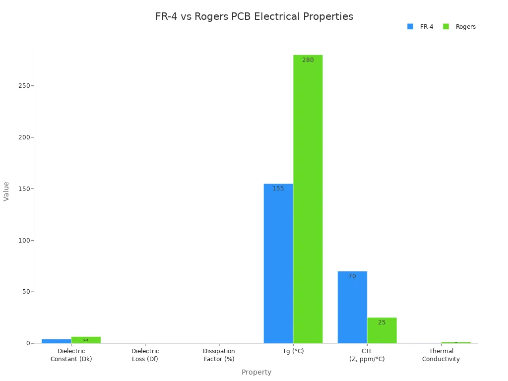
Rogers pcb design lets engineers control impedance and signal speed. This helps advanced systems work better.
Signal Loss and Data Rates
Signal loss is important in fast circuits. Rogers pcb design keeps signal loss low, even at 10 GHz and higher. FR-4 loses more signal as frequency goes up. Rogers pcb design uses a dissipation factor below 0.004. FR-4 can reach 0.03. This means rogers pcb design supports higher data rates and longer traces.
Material | Frequency | Dissipation Factor (Df) | Signal Attenuation |
|---|---|---|---|
Standard FR-4 | 10 GHz | 0.018–0.022 | Manageable |
Rogers RO4350B | 10 GHz | 0.0037 | Significantly lower |
Material | Dissipation Factor (Df) | Signal Loss |
|---|---|---|
FR-4 | 0.020–0.030 | Higher |
Rogers | <0.004 | Lower |
Rogers pcb design keeps data moving fast. High-speed traces show up to 35% less signal loss compared to FR-4. This makes rogers pcb design a good choice for AI servers, RF circuits, and data centers.
High data rates, like 400G and 800G, need low-loss pcb materials. Rogers pcb design meets these needs and keeps signal quality high.
Cost and Application Considerations
Cost matters when picking materials. Rogers pcb design costs more than FR-4. FR-4 works well for products and projects with small budgets. Rogers pcb design fits best in jobs needing high reliability and performance.
Projects with small budgets should use FR-4.
Rogers pcb design is good for aerospace, defense, and advanced computing.
Mass production uses FR-4 for lower costs.
Application Type | Benefit of Rogers PCB Materials |
|---|---|
AI Server Applications | High-frequency performance, low signal loss, superior thermal stability |
RF and Microwave Circuits | More stable dielectric characteristics across frequency ranges |
High-Speed Traces | Up to 35% less signal degradation compared to FR4 |
Rogers pcb design is worth the higher price in important systems. These systems need stable signals, low loss, and strong heat control. FR-4 is the best choice for simple, cost-driven designs.
Rogers pcb design gives reliability and speed where it matters most.
Selecting Rogers PCB Materials
Choosing the Right Laminate
Engineers need to pick the right laminate for good high-frequency performance. Rogers has many pcb materials for different jobs. The choice depends on a few things:
Think about the frequency you need. If your circuit works from 500 MHz to 5 GHz, RO4003C is a good and cheap choice. For microwave systems between 5 and 20 GHz, RO3003 and RO4835 give steady and low-loss results. For mmWave designs above 20 GHz, RT/duroid 5880 and RO3003 are best.
Look at the dielectric constant. Lower Dk values make signals move faster and help with impedance matching. Dk values from 2.2 to 3.0 are good for mmWave and wideband antennas. Dk values from 3.0 to 4.0 fit most RF and 5G systems. Dk values from 6.0 to 10.0 work well for small filters.
Think about heat. High thermal conductivity, high glass transition temperature, and low expansion keep the board stable when it gets hot.
Check the environment. For space, engineers use laminates that do not let out gas and can handle radiation. For military, they pick materials that can take big temperature changes, shaking, and shocks.
Tip: Picking the right laminate for your job makes your pcb design work well and last longer.
Design and Layout Tips
Rogers pcb design works best with careful planning and layout. Engineers use these tips:
Pick the right Rogers material for your frequency, power, and heat needs.
Use field solvers to check insertion loss and see how well the board will work.
Try hybrid stackups to keep signals strong.
Choose the best copper weight (1-2 oz) and use smooth foil to lower skin effect losses.
Put vias in smart places. Blind or buried vias help lower stub inductance.
Add thermal vias under transistor flanges to move heat away.
Pick the right substrate thickness for the signal length and power.
Follow IPC-A-600 rules for making the board.
Put decoupling capacitors close to power pins to stop noise.
Stitch ground planes together to stop cavity resonances.
Note: Good planning and layout keep signals clear and cut down on mistakes in high-frequency circuits.
Manufacturing Best Practices
Manufacturers must be careful with Rogers pcb materials to keep them working well. They follow these steps:
Handle laminates gently so they do not get scratched or dirty.
Use slow drill speeds and feed rates to stop overheating and keep holes nice.
Use the right lamination steps for strong sticking.
Change etching to stop too much copper from being removed.
Figure out trace widths and spacing using the dielectric constant.
Use the right machining and drilling for good results.
Control heat during use.
Test and check boards to make sure they work and last.
Callout: Careful work in making Rogers pcb design helps it perform well and stay reliable in tough places.
Real-World Applications
RF and Microwave Devices
Engineers use rogers materials in many real-world jobs for RF and microwave. These pcb materials work in telecom, rf, microwave, and 5G systems. Rogers is great for high-frequency uses because it has very little loss, handles heat well, and does not expand much. These things make rogers the best pick for rf designs that need strong signals and to work all the time. Many gadgets, medical tools, and fast industrial electronics use these materials too. Rogers pcb materials help keep signals clear and working right, even when frequencies go up.
Rogers materials keep signals from getting weak and help things work well, which is very important for rf jobs.
High-Speed Digital Circuits
Rogers pcb materials are important in fast digital circuits. Big telecom companies have seen much faster data speeds and less waiting time when they use rogers pcb in their 5G base stations. Rogers 4350B pcb helps control heat and keeps signals strong, so data moves faster and there is less delay. These materials give low signal loss and steady work, which is needed for high-frequency jobs. Rogers pcb keeps dielectric loss low and controls impedance well, so signals stay clear and strong in fast systems.
Rogers pcb helps data move fast and keeps things working right.
Fast circuits do better because rogers materials lose less signal and stay steady.
Aerospace and Defense Uses
Aerospace and defense need materials that can handle tough places. Rogers pcb materials have low loss, handle heat well, and are made very carefully, so they are good for important systems. Rogers 3003 pcb is used in special antennas, satellite parts, and transceivers. These jobs need steady dielectric properties so circuits work the same way, even when things change. Rogers materials help keep signal loss low and work steady in aerospace and defense rf jobs.
Rogers pcb materials give the strong work and steady results needed for advanced aerospace and defense jobs.
Rogers PCB materials help engineers keep signals strong and clear. They also make high-frequency circuits work better. These materials let circuits run faster and stay reliable. Picking the right rogers laminate is important for advanced designs. Engineers should look at their boards and see if rogers is a good choice.
For what to do next, read datasheets or ask suppliers which rogers material is best for your project.
FAQ
What makes Rogers PCB materials better for high-frequency solutions?
Rogers PCB materials have steady dielectric properties and low signal loss. These things help engineers make high-frequency circuits that work well. Signals stay clear and strong, even at very fast speeds.
Can Rogers PCB materials improve high-frequency amplifier design?
Yes. Rogers PCB materials lower signal loss and keep impedance steady. These features help engineers get better performance and more reliable high-frequency amplifier designs.
Are Rogers PCB materials difficult to manufacture?
Manufacturers must use special steps when working with Rogers materials. They need to drill, press, and clean the boards carefully. These steps help keep the material’s special properties and make sure the boards are high quality.
Do Rogers PCB materials cost more than FR-4?
Rogers PCB materials usually cost more than FR-4. The higher price is because they work better, last longer, and are good for tough jobs like aerospace, defense, and fast data systems.
Where are Rogers PCB materials most commonly used?
Engineers use Rogers PCB materials in RF devices, microwave circuits, 5G systems, and aerospace electronics. These jobs need steady signals, low loss, and good heat control.
See Also
Exploring Manufacturing and Design Aspects of High Frequency PCBs
Integrating Rogers Material and TG170 in Hybrid PCB Designs
Exploring Rogers R4350B, R4003, and R5880 for RFPCB Applications
Defining High-Speed PCBs and Their Key Characteristics
Identifying Optimal Materials for High-Speed PCB Design Projects
