How Industrial PCB Production Works from Design to Assembly
Industrial pcb production begins with design and goes through these steps:
Cut the laminate for the printed circuit board.
Make the inner circuits and stack the layers.
Drill holes and add copper plating.
Make outer circuits, put on solder mask, and finish.
Test, put together pcba, and send it out.
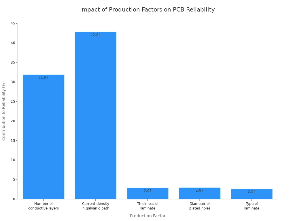
Each step changes how a pcb works and affects quality. The number of layers and the galvanic bath current density matter most for reliability, as shown below:
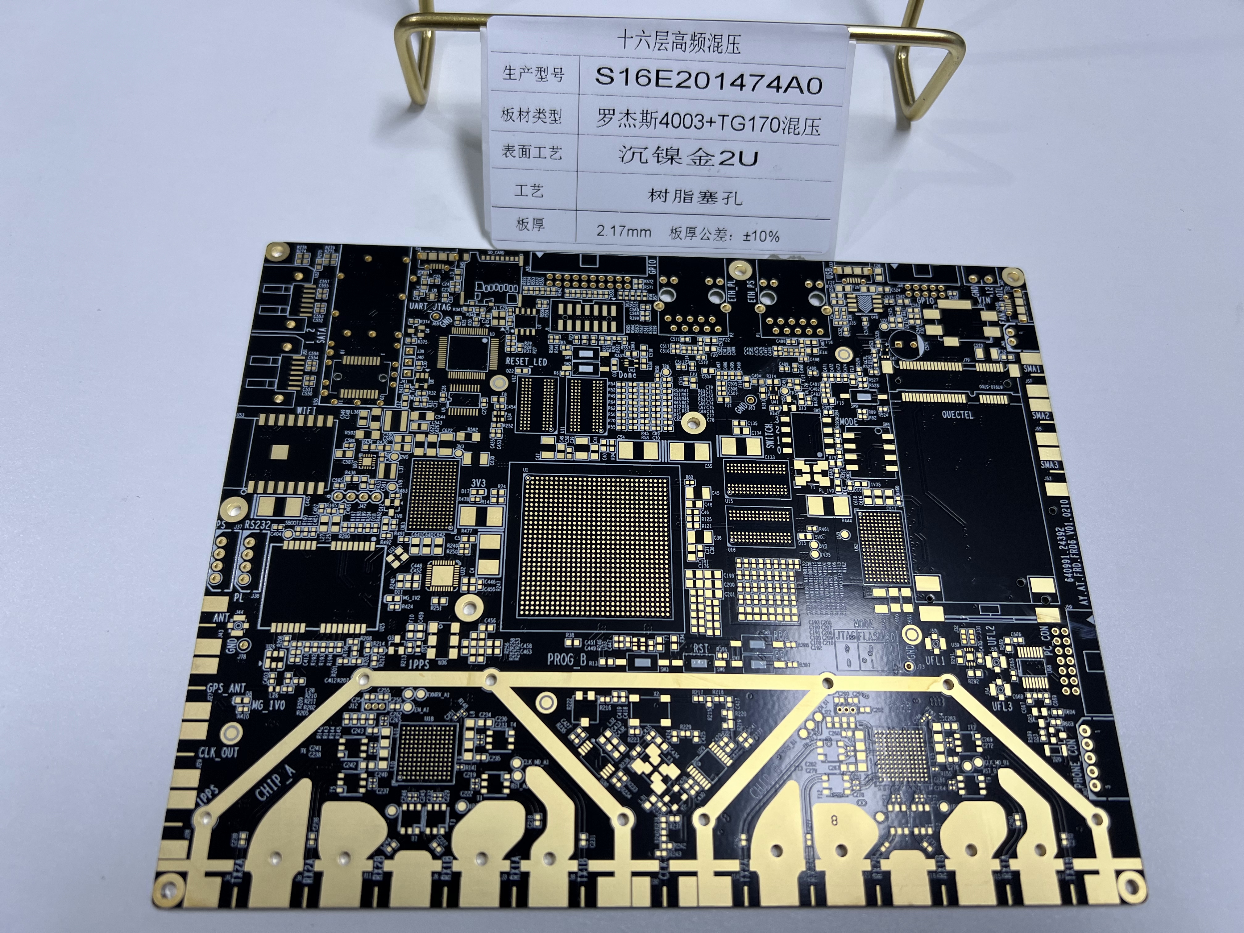
You can see LT CIRCUIT leads with good design, accurate gerber files, and careful pcba testing in every printed circuit boards process.
Key Takeaways
Begin PCB production with a clear design. Use the right tools and check all files well. This helps stop mistakes from happening.
Pick the best materials and follow each step closely. This makes sure the circuit boards are strong and work well.
Test each board carefully and pack it safely. This helps you get good PCBs you can trust.
Printed Circuit Board Design
Schematic and Layout
First, you need to know what your project needs. You figure out the current and voltage. You also decide where each part will go. Then, you make a schematic. This shows how all the parts connect and work together. You use tools like KiCad, Zuken CADSTAR, or Autodesk Eagle. These help you draw the schematic and plan the pcb layout. The programs let you place parts and set up the pcb stackup. They also help you follow IPC standards. A good pcb layout keeps signal paths short. This helps lower noise. You add drill holes and labels for assembly and fixing problems. Careful design now helps your printed circuit boards work well and last longer.
Output Files and Documentation
When you finish, you must make pcb design output files. These files include gerber files. Gerber files tell machines how to build your pcb. You also need a bill of materials, or bom. The bom lists every part for your printed circuit board. You need other files too. These are assembly drawings, fabrication drawings, and pick-and-place files for pcba. Sometimes you need testpoint reports and 3D drawings. LT CIRCUIT uses special tools to make sure your files are clear and correct. This helps stop mistakes and makes pcb manufacturing faster.
Note: Always check your gerber files, bom, and drawings. Make sure they match your design. This step helps stop errors during printed circuit boards production.
DFM Check
Before you send your pcb design output files to the factory, you must do a DFM check. This means Design for Manufacturability. The DFM check looks for problems that could hurt your printed circuit boards. A good DFM check can stop up to 30% of common problems. These problems include cracks or bubbles. You check your gerber files, bom, and drawings for spacing and material rules. LT CIRCUIT checks every design to meet customer needs and industry rules. This makes sure your pcba process works well.
Industrial PCB Production Steps
Material Selection and Review
You begin by picking the right materials for your project. The material you choose changes how your circuit board works. It also affects how long it lasts and how it handles heat or stress. Most pcb production uses FR-4. This material gives good electrical insulation and is strong. It also costs less than some other choices. Sometimes, you need special materials. Polyimide is used for flexible boards. Aluminum-based materials help control heat better. LT CIRCUIT checks every material to fit your project’s needs. They also follow strict rules like RoHS and REACH.
Here is a table that shows common materials and what they do:
Material Type | Advantages | Typical Applications and Effects on Performance |
|---|---|---|
FR-4 | Good insulation, strong, cost-effective | Most consumer, industrial, and automotive pcbs |
CEM-1 / CEM-3 | Low cost, supports simple designs | Home appliances, low-cost electronics |
Polyimide | Flexible, high heat resistance | Wearables, medical, automotive |
IMS (Aluminum-based) | Great heat dissipation | LED lighting, power supplies |
Ceramic | High temp, stable, brittle | Power electronics, sensors |
PTFE | Low loss, high frequency | RF, microwave, telecom |
You also need to check each material for heat, chemicals, and strength. LT CIRCUIT uses a checklist for glass transition temperature, dielectric constant, and thermal conductivity. This helps you stop problems before they start in the pcb manufacturing process.
Tip: Always pick the right material for your job. For example, use high-Tg FR-4 if your board gets hot.
Fabrication Process
The fabrication process turns your design into a real board. You start by checking your gerber files and drawings. LT CIRCUIT uses special CAM software to look for mistakes in your files.
Here are the main steps in the pcb manufacturing process:
Design Review and DFM Check: You and the factory check your files for problems.
Printing and Imaging: Special printers make films from your gerber files. These films show where copper should stay or go.
Photoresist Application and UV Exposure: A light-sensitive layer covers the board. UV light hardens the parts that match your circuit.
Etching: Chemicals take away extra copper. Only your circuit paths stay.
Layer Alignment and Lamination: Machines stack and press layers together. They use holes to keep everything lined up.
Drilling and Plating: Machines drill holes for vias and through-holes. Copper plating connects the layers.
Solder Mask Application: A green or other color solder mask covers the board. It protects the traces and stops solder bridges.
Surface Finishing: LT CIRCUIT adds finishes like ENIG, HASL, or immersion silver. These finishes protect copper and help with soldering.
Automated Optical Inspection (AOI): Cameras look for mistakes before the next step.
You do these steps for each layer in a multilayer pcb. LT CIRCUIT uses Laser Direct Imaging and AOI to make sure every board is made well.
Assembly and Soldering
After making the board, you add the electronic parts. This is called the assembly process. There are two main ways to do this: Surface Mount Technology and Through-Hole Technology.
SMT: Machines put small parts right on the board’s surface. This is fast and good for small, crowded boards.
THT: You put parts with leads through holes in the board. This makes strong connections for heavy or high-power parts.
Hybrid Assembly: Sometimes, you use both SMT and THT on one board. This gives you the best mix of strength and size.
There are different ways to solder the parts:
Reflow Soldering: Heats the whole board to melt solder paste for SMT parts.
Wave Soldering: Runs the board over a wave of melted solder for THT parts.
Selective Soldering: Only solders certain spots. This is good for mixed boards.
LT CIRCUIT uses machines to place parts, ovens to heat boards, and lines for wave soldering. This helps every printed circuit board assembly meet high standards. AOI and strict IPC standards help stop problems like cold joints or solder bridges.
Quality Control and Testing
Quality control is very important in pcb manufacturing. LT CIRCUIT uses many tests to find problems early and make sure your pcba works.
What It Checks For | Benefit | |
|---|---|---|
AOI | Missing parts, wrong placement, solder defects | Finds visual errors quickly |
SPI | Solder paste amount and placement | Prevents soldering problems |
X-ray Inspection | Hidden solder joints (like BGA) | Finds internal defects |
ICT | Shorts, opens, wrong values, solder faults | Checks each part and connection |
FCT | Real-world function, power-up, signals | Makes sure the board works as designed |
E-test | Continuity and isolation of traces | Finds open or short circuits |
Flying Probe Test | Electrical tests for small batches or prototypes | Flexible and thorough for low volumes |
LT CIRCUIT also does manual checks and keeps records for tracking. This gives you a pcba you can trust.
Note: Most problems come from soldering, placing parts, or dirt. LT CIRCUIT checks equipment, trains workers, and audits the process to stop these issues.
Packaging and Delivery
When your pcba passes all tests, it needs protection for shipping. LT CIRCUIT uses special packaging for your board’s size and weight. You get anti-static bags, foam, and wraps to stop static, shocks, and water.
You also see clear labels with product details and how to handle it. LT CIRCUIT follows IPC-1601 A and MSL rules to keep boards safe. Boards are baked before shipping to remove water, and packaging meets world rules.
Fast, safe delivery is important for customers. LT CIRCUIT uses a master scheduler and good shipping to meet your deadlines. You can track your order and get help at every step.
Tip: Always keep your pcba dry and safe from static until you use it.
You need to do every step in PCB production carefully. This helps make sure the boards work well and last long. Good design, careful building, and strong testing make boards you can trust. LT CIRCUIT is a top company because they use smart designs and have skilled workers. They also follow strict rules. It is important to respect the skill and care that go into making modern circuit boards.
FAQ
What files do you need to start PCB production?
You need Gerber files, a bill of materials (BOM), and assembly drawings. These files tell the factory how to build your board.
How does LT CIRCUIT test your PCBs?
LT CIRCUIT uses AOI, flying probe, and E-test. These tests check for errors and make sure your board works before shipping.
Can you choose different surface finishes for your PCB?
Yes! You can pick ENIG, HASL, or immersion silver. Each finish helps with soldering and protects your board from damage.
See Also
Step-By-Step Guide To Printed Circuit Board Production
In-Depth Explanation Of The PCB Fabrication Method
Key Procedures For Rapid Turnkey Printed Circuit Assembly
Comprehensive Breakdown Of Multilayer PCB Manufacturing Steps
Using Horizontal Copper Sinking Techniques In PCB Fabrication