The influence of lead-free assembly components on the reliability and material performance of printed circuit boards

Lead-free assembly components impact the performance of printed circuit boards. Industry data indicates that increasing the heat from 245°C to 260°C can reduce the number of thermal cycles before failure by up to 65%. Common issues include a higher risk of delamination, micro-cracks, and an increased demand for high-quality materials.
Key Takeaways
Lead-free assembly needs more heat. This puts stress on PCB materials. It can cause cracks and delamination. It may also lead to early failures. Picking materials with high heat resistance helps stop damage. Controlling the temperature closely is also important.
Using the right surface finishes is helpful. Lead-free solder alloys make PCBs last longer. They lower risks like corrosion and tin whiskers. Working with skilled manufacturers is important. This makes sure materials are safe and high quality.
Good process control is needed. This includes training, inspections, and testing. Smart design choices also help. These steps make PCBs more reliable. They help PCBs last longer, even with lead-free assembly challenges.
Lead-Free Assembly Components: Main Effects
Higher Processing Temperatures
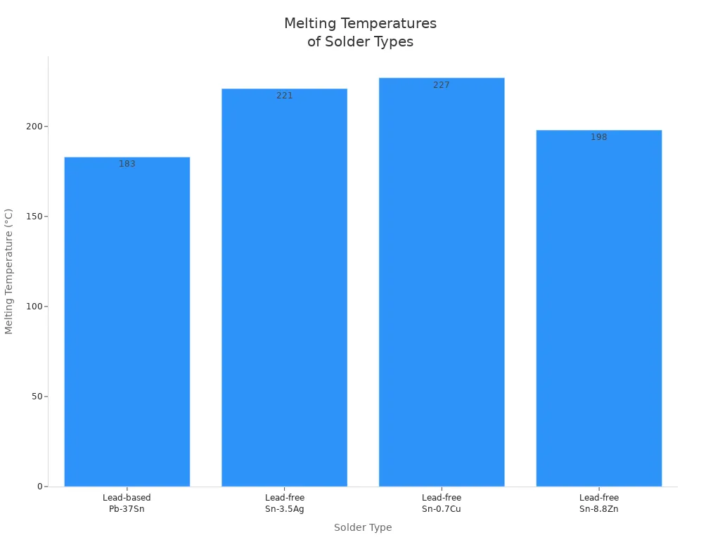
Lead-free assembly components need higher reflow temperatures than leaded ones. Most lead-free solders melt between 217°C and 227°C. Leaded solder melts at 183°C. This means manufacturers set reflow ovens to 240°C to 270°C. The process window is smaller, so thermal profiling must be exact. If not, problems like cold solder joints, solder balling, or damaged parts can happen.
Note: Controlling preheat rates and soak temperatures helps stop thermal shock and makes sure flux works right.
The reflow process for lead-free assembly components has several steps:
Reflow Stage | Lead-Free Temperature Range (°C) | Notes |
|---|---|---|
Preheat | Preheat slope rate 0.75 - 2 °C/sec | |
Soak | ~217 | Soak slope rate 0.5 - 1 °C/sec |
Peak Reflow | 240 - 248 | Peak lasts 10 - 30 seconds |
Cooling | Down to 75 | Cooling slope rate about twice preheat |
It is important to keep the right temperature at all spots on the PCB. Small parts near the edges heat up faster. Big parts in the middle heat up slower. Technicians use thermocouples to check these places. This helps make sure all solder joints get hot enough but do not overheat.
Higher reflow temperatures cause more stress in PCB assemblies. This can lower product reliability. Manufacturers now use tougher tests to check quality. Some companies try new materials and methods, like nano-solder, to lower melting points and reduce stress.
Material Degradation
High processing temperatures from lead-free assembly components are hard on PCB materials. Regular FR4 laminates have a glass transition temperature (Tg) around 150°C. These often cannot handle the heat. If the PCB runs at or above Tg, the laminate gets weak. This can make the board change shape and cause delamination.
Staying at high temperatures for a long time breaks down resin faster. This causes outgassing and lowers insulation resistance.
The laminate, copper traces, and solder joints expand differently when heated. This creates stress during heating and cooling. These stresses can make solder joints tired, crack parts, break vias, and warp the PCB.
High heat also makes intermetallic compounds in solder joints grow faster. This makes them brittle and easier to break.
Manufacturers now pick laminates with higher Tg, decomposition temperature (Td), and controlled coefficients of thermal expansion (CTE). These features help the PCB survive tough lead-free assembly. But Tg alone is not enough for strength. Td and CTE are also needed to stop failures and long-term damage.
Tip: Using high-temperature laminates and changing how you make PCBs can help them last longer and work better.
Electrical properties also get worse at higher temperatures. More leakage current and lower impedance can happen during heating and cooling. This can hurt the performance of sensitive circuits.
Reliability Challenges
Pad Cratering
Pad cratering is a big problem in making modern PCBs. This happens when the copper pad comes off the fiberglass layer. It leaves a small hole that looks like a crater. Lead-free assembly components need higher heat, which makes pad cratering more likely. This is worse when the board bends or heats up and cools down many times. Solder mask defined (SMD) pads can help lower this risk. Tests show SMD pads work better than other pad types with lead-free solders. But even with better pads, lead-free assemblies can still get weaker after aging. Old Sn-Pb solder joints sometimes get stronger after the same tests. Engineers must pick the right pad type and materials to stop pad cratering with lead-free parts.
New Failure Modes
Using lead-free assembly components brings new ways for PCBs to fail. These problems did not happen much with leaded solder. Some of these are:
Brittle fracture: Solder joints can break suddenly if stressed. This can happen during building, shipping, or heating and cooling. Lead-free solders are more brittle because of their higher heat and different alloys.
Warpage: PCBs can bend or twist from heat or water. Heavy parts or uneven layers make this worse during reflow.
Creep corrosion: Lead-free finishes like immersion silver can rust faster in tough places. This can cause electrical problems.
Fatigue: Heating and cooling over and over makes cracks in solder joints. Parts and boards expand at different rates, which adds risk.
Conductive anodic filaments (CAFs): Water and high voltage can make tiny paths inside the PCB. High soldering heat can weaken the glass-resin bond, making this easier.
Tin whiskers are another problem with lead-free solders. These are tiny, hair-like crystals that grow on solder. They can cause shorts in the circuit. Leaded solder almost never has this issue. Because of these new failure modes, engineers must change how they test and design PCBs.
Note: Using the wrong solder or bad reflow settings can make these problems worse. Good process control is very important.
Reduced Cycles to Failure
Lead-free assembly components often make PCBs fail sooner. Higher heat and longer times stress the board and its parts. This can cause small cracks, layers coming apart, and early breaks in vias and solder joints.
One big company found that mixing lead-free solder with Sn/Pb-coated parts made the solder joints brittle. This mix caused the joints to break and fail in the field. Using only lead-free parts and coatings is needed to stop these problems.
Thermal cycling tests show reliability drops a lot for weak microvias after lead-free processing. The table below shows the results:
Microvia Condition | Preconditioning / Assembly Type | Thermal Cycles to Failure (Mean) | Relative Entitlement (%) | Reduction Compared to As-Received |
|---|---|---|---|---|
Marginal Microvias | As Received | 788 | 100% | N/A |
Marginal Microvias | Tin-Lead Preconditioning (6X 230°C) | ~441 (56%) | 56% | 44% |
Marginal Microvias | Lead-Free Preconditioning (6X 260°C) | 4 | 1% | 99% |
Well-Fabricated Microvias | As Received | 1,923 ± 155 | 100% | N/A |
Well-Fabricated Microvias | Lead-Free Preconditioning + 2,000 cycles at 190°C | 1,549 ± 649 | ~80% | 20% |
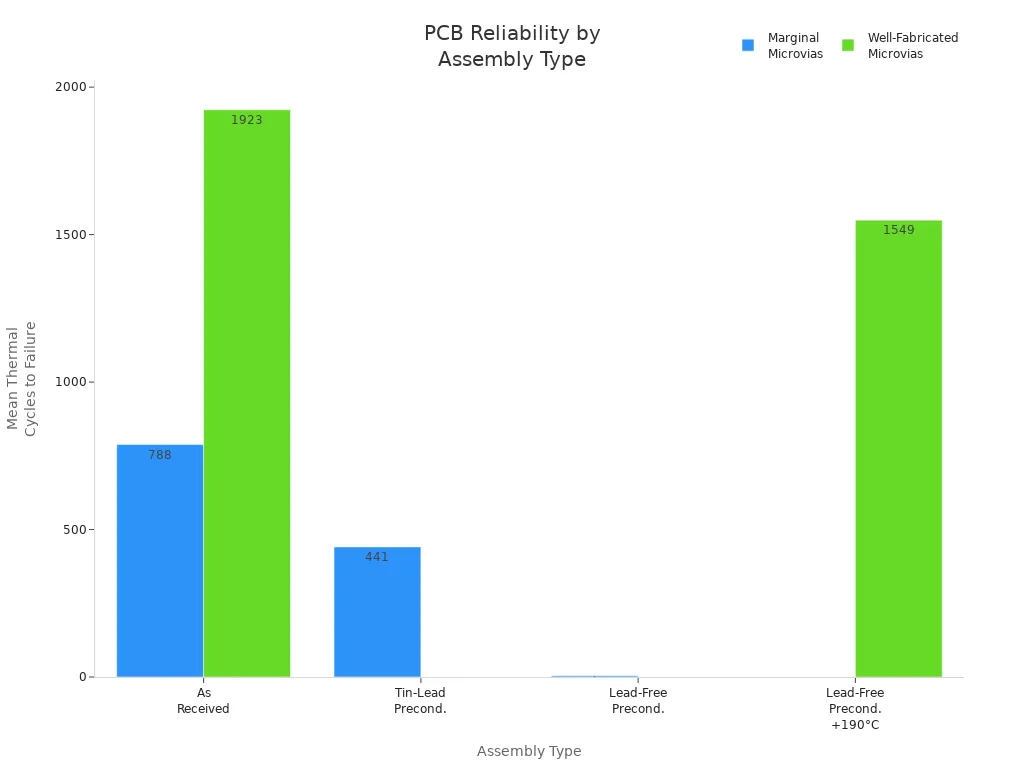
The data shows weak microvias can lose almost all their strength after lead-free preconditioning. They drop from 788 cycles to just 4 before breaking. Strong microvias also get weaker, but not as much. This means better materials and tougher tests are needed for high heat.
Other industry data shows the same thing:
Lead-free solder joints rust 25-35% faster than leaded ones in salt spray.
In high humidity, lead-free assemblies leak more electricity.
Shocks and shaking cause 15-30% more breaks in lead-free assemblies.
Lead-free joints crack 20-40% sooner than leaded ones in thermal shock.
Doing repairs many times hurts lead-free assemblies more, with up to 40% less performance after three fixes.
Leaded assemblies made at 220°C can last about 40 thermal cycles before failing in some materials. Lead-free assemblies made at 260°C may last only 10 cycles. The extra heat and new failure types in lead-free assemblies mean engineers need new ways to design and test them.
Engineers in aerospace, defense, and car industries sometimes do not have to use lead-free rules because of these reliability worries.
Material and Design Factors
Surface Finishes
Surface finishes are important for how long PCBs last. They matter most when boards get bent or pushed. Some finishes, like immersion tin and immersion silver, make intermetallic compounds during soldering. These compounds are called Cu6Sn5, Cu3Sn, and Ag3Sn. They help solder joints stay strong when heated or pressed. ENEPIG finishes also make strong bonds. This makes them good for mixed assembly types. The table below shows different finishes and what they do:
Surface Finish | Reliability Aspect | Key Benefits |
|---|---|---|
ENIG | Oxidation resistance | Durable, corrosion-resistant |
Immersion Nickel | Wear resistance | Good for high-stress environments |
Hard Gold | Mechanical wear resistance | Highly durable, used in rugged settings |
Sometimes, tin whiskers can grow on some finishes. This happens most with pure tin. Tin whiskers are tiny metal hairs. They can cause short circuits in the board. Immersion tin finishes usually make intermetallic compounds instead of whiskers. This helps stop failures. Humidity and stress can make whiskers grow faster. So, engineers must pick finishes with care.
PCB Material Selection
Picking the right PCB material is very important. High heat during assembly can make boards bend or twist. Materials with high decomposition temperatures (Td) and glass transition temperatures (Tg) handle heat better. RoHS-compliant laminates follow strict safety and environmental rules. They also fight off chemicals and water.
High melting temperatures (220°C to 240°C) need materials that stay strong in heat.
Low coefficients of thermal expansion (CTE) help stop cracks and delamination.
Moisture resistance keeps boards safe during soldering.
RoHS compliance keeps people and the environment safe.
Design Variations
Engineers choose materials based on what the product needs. For most electronics, lead-free FR-4 epoxy glass fiber works well. More complex products use high Tg FR-4. Boards that must last a long time may need FR-5 or metal bases. Flexible or high-heat circuits often use polyimide. High-frequency boards work best with Teflon glass fiber. Each material has its own mix of cost, performance, and reliability.
Tip: Boards for 5G, cars, or planes need special materials. These must have high thermal and electrical performance.
Testing and Evaluation
Thermal Cycling
Thermal cycling tests help engineers see how PCBs last over time. They put boards in special chambers. The temperature goes up and down between set high and low points. Each cycle keeps the board at these temperatures for a while. This copies what happens in real life. The test repeats many times to act like years of use. The PCB gets bigger and smaller as it heats and cools. These changes can make cracks or other problems in solder joints and materials.
Thermal cycling also shows how materials and assembly methods change reliability. For example, where bolts go and how they are fastened changes stress on solder joints. Changing these things can help the board last longer and not break. After testing, engineers look at the boards with their eyes and with microscopes to find damage.
Stress and Life Testing
Stress and life tests help engineers find weak spots before customers use the product. Some common tests are Automated Optical Inspection (AOI), In-Circuit Testing (ICT), and Functional Testing. AOI uses cameras to find problems like bad soldering or parts in the wrong place. ICT checks if each part works right with electricity. Functional Testing acts like real use to make sure the board works as it should.
Testing Method | Main Benefit | Limitation |
|---|---|---|
AOI | Finds visual defects fast | Misses inside problems |
ICT | Finds shorts and open circuits | Needs costly tools |
Functional Testing | Checks if board works in real life | Takes a lot of time |
Engineers also use computer models, like finite element analysis, to guess how solder joints will act under stress. These models help pick the best designs and materials for long life. By using both real tests and computer models, makers can test boards better and make higher quality products.
Best Practices for Lead-Free Assembly Components
Material Selection
Engineers make PCBs more reliable by picking good materials for lead-free assembly components. They usually pick SAC or SnAgCu solder alloys. These alloys follow RoHS rules and make strong joints. Surface finishes like ENIG, Immersion Silver, OSP, and Immersion Tin help stop rust and keep the board working well. Laminates and other PCB materials must also follow RoHS rules. Many companies work with skilled PCB makers. These partners help pick the right materials, check the rules, and lower risks.
Recommended steps for material selection:
Pick lead-free solder alloys like SAC or SnAgCu.
Use RoHS-approved surface finishes such as ENIG, Immersion Silver, OSP, or Immersion Tin.
Choose laminates that follow RoHS rules.
Work with manufacturers who know about RoHS and lead-free needs.
Process Control
Good process control helps make high-quality PCBs. Teams use industry rules like J-STD-001 and IPC-A-610. These rules tell how to solder, check, and approve boards. Training and certificates for workers help stop mistakes. AOI and X-ray machines find problems early. ICT checks if each part works right. Functional Testing makes sure the board works in real life.
Use trained inspectors and keep training workers.
Use AOI and X-ray checks to find problems early.
Do ICT and functional tests to check quality.
Write down every step and use clear rules.
Design Strategies
Designers use smart ideas to make boards last longer. They try to use fewer solder points and layers. They pick the best board size and copper thickness. New tools like SMT and laser drilling help make boards more exact. Good design means simple layouts and using common parts. Making test boards and writing clear notes help stop mistakes.
Tip: Remember to think about the environment and being green when designing for lead-free assembly components.
Lead-free assembly components make PCBs face more heat stress. They also change how and when boards can fail. The process window is smaller, so it is harder to get right. Picking the right materials and making strong designs help PCBs work well. Good process control is also important for performance. Engineers should use new rules and test boards carefully. They must follow new steps to keep PCBs working for a long time, even in tough places.
FAQ
What is the main reason for using lead-free assembly components?
Manufacturers use lead-free parts to follow environmental rules like RoHS. These rules lower toxic chemicals in electronics and keep people safer.
How do higher reflow temperatures affect PCB reliability?
Higher reflow temperatures put more stress on PCB materials. This can make cracks, delamination, and cause products to not last as long. Engineers need to pick materials that can handle this heat.
Can engineers prevent tin whisker growth in lead-free assemblies?
Engineers use surface finishes like ENIG or Immersion Tin. These finishes help stop tin whiskers from growing and make boards last longer.
See Also
How LDI Technology Impacts The Quality Of PCB Products
Enhancing LED And Power Electronics With Aluminum-Backed PCBs
Why RoHS Compliance Matters In Today’s PCB Production
Key Precautions To Consider When Designing PCB Circuit Boards