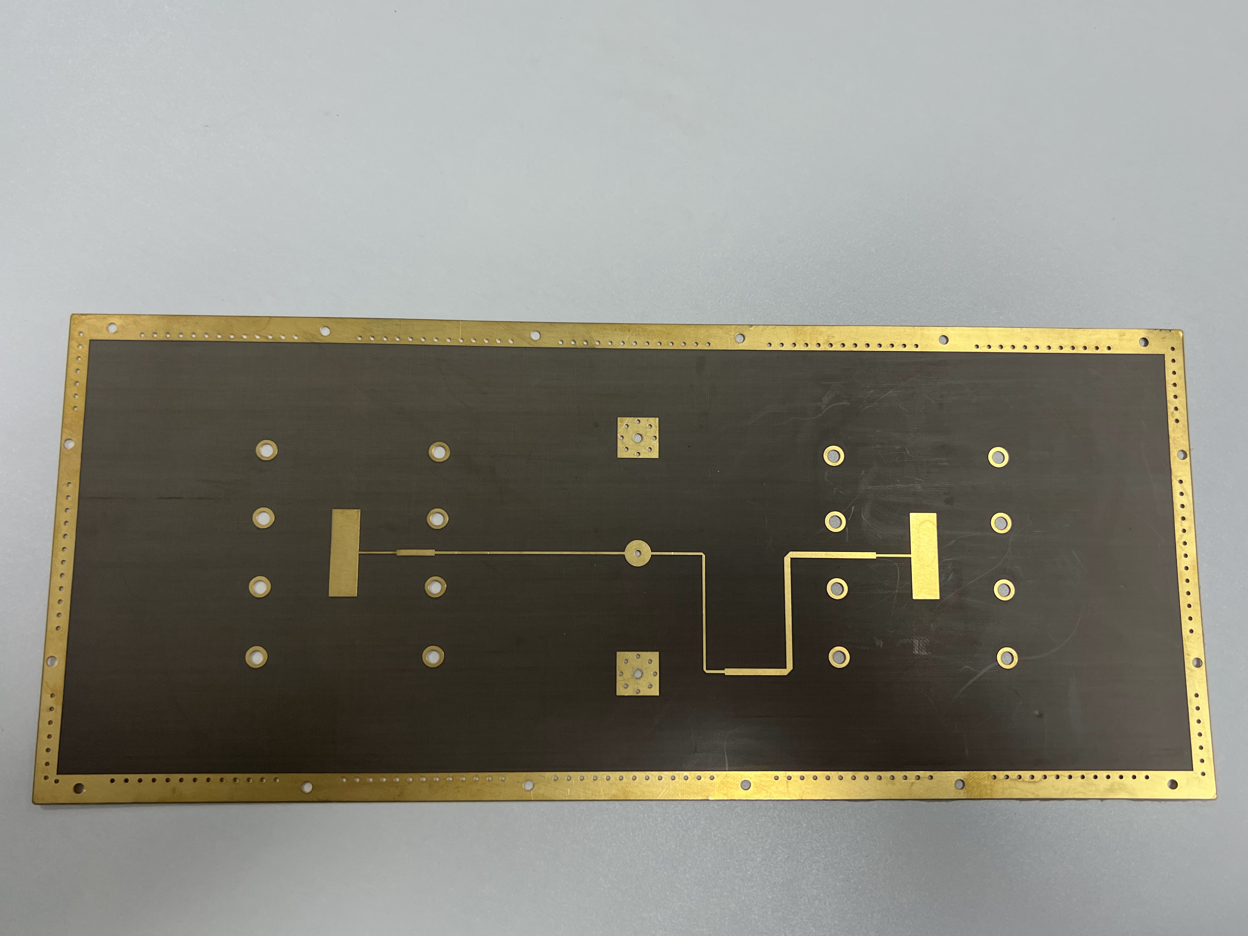
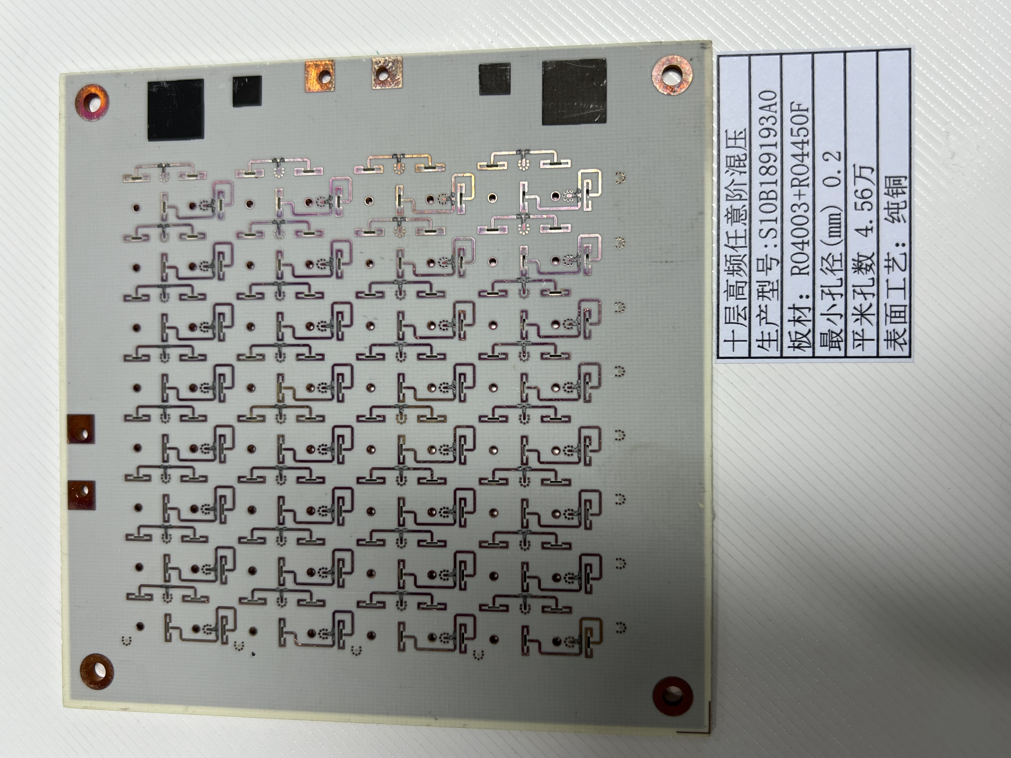
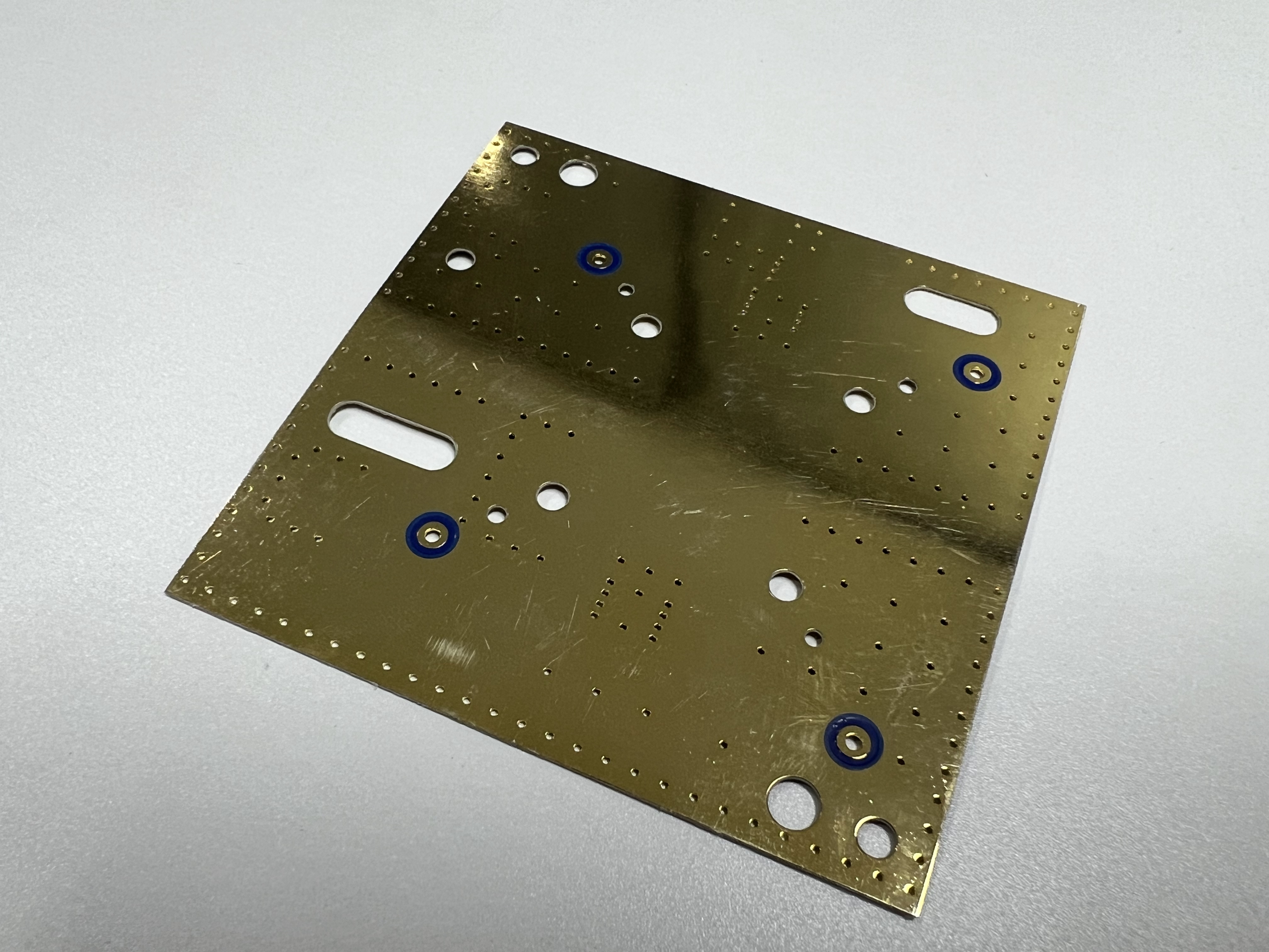
How to Choose the Right Materials for High-Frequency PCB Projects

Engineers need to look at electrical, thermal, and mechanical properties when picking materials for any High-Frequency PCB. The material you pick changes how well signals work and how reliable the board is. Better materials help stop signal loss and make the board work better. Picking the right material makes sure the circuit works well and does what it should.
Key Takeaways
Pick PCB materials with low dielectric constant (Dk) and low dissipation factor (Df). This helps signals stay fast and clear in high-frequency circuits.
Choose materials that can handle heat, moisture, and stress. This makes sure your PCB works well and lasts longer in hard places.
Use a simple selection process. First, know what your project needs. Next, compare different materials. Then, test your choices. Talk to manufacturers for advice. Try to balance good performance with the cost.
Importance of Material Choice
Signal Integrity
The material you pick is very important for signal integrity in any High-Frequency PCB. Engineers want materials that keep signals strong and clear. If you pick the wrong material, signals can get weak or noisy. This can cause mistakes in the circuit.
Tip: Materials with a low dielectric constant and low loss let signals move faster and stay clear.
Designers often use a checklist to compare materials:
Dielectric constant (Dk)
Dissipation factor (Df)
Thickness and uniformity
Good materials keep signals sharp and stop interference. This helps the board work well, even when it runs fast.
Reliability
Reliability means the material must handle stress, heat, and moisture well. Some materials change shape when they get hot or cold. This can break solder joints or traces. Water can get into some materials and cause rust or short circuits.
Property | Impact on Reliability |
|---|---|
Thermal stability | Stops the board from bending |
Lowers the chance of rust | |
Mechanical strength | Stops cracks |
Engineers pick materials that stay the same over time. Good materials help the High-Frequency PCB last longer and work well in hard places.
High-Frequency PCB Materials

Picking the right material is very important for any High-Frequency PCB project. Each type of material has special electrical and mechanical features. Engineers need to know these differences to choose the best one for their designs.
PTFE-Based
PTFE-based materials use polytetrafluoroethylene as the main part. These materials have a very low dielectric constant (Dk) and a low dissipation factor (Df). This lets signals move fast with little loss. PTFE-based laminates can handle heat and chemicals well. They also do not soak up much water.
Pros:
Great signal integrity at high frequencies
Low signal loss
Works well in tough places
Cons:
Costs more than regular materials
Harder to make because they are soft and bendy
Microwave circuits
RF antennas
Satellite communication boards
Note: PTFE-based materials are best when you need clear and fast signals.
Rogers Series
Rogers materials are made for high-frequency jobs. They come in many types with different Dk and Df values. Rogers laminates work better than FR-4 but are easier to make than pure PTFE.
Pros:
Steady electrical features
Lower loss than FR-4
Good at handling heat
Cons:
Costs more than FR-4
Some types are still harder to make than FR-4
Typical Use Cases:
High-Frequency PCB designs for wireless base stations
Radar systems
Advanced communication devices
Material | Dielectric Constant (Dk) | Dissipation Factor (Df) | Cost | Manufacturability |
|---|---|---|---|---|
PTFE-Based | 2.1 - 2.6 | <0.001 | High | Difficult |
Rogers Series | 2.2 - 3.5 | 0.001 - 0.003 | Medium-High | Moderate |
FR-4 | 4.2 - 4.8 | 0.015 - 0.025 | Low | Easy |
FR-4
FR-4 is the most used PCB material. It is made from woven glass and epoxy resin. FR-4 is cheap and simple to use. But it does not work well at high frequencies. The higher Dk and Df cause more signal loss and signal problems.
Pros:
Cheap
Simple to make
Easy to find
Cons:
Bad signal integrity at high frequencies
More signal loss
Not steady in very tough places
Typical Use Cases:
Consumer electronics
Low-frequency digital circuits
Prototyping and general-purpose boards
Tip: For most High-Frequency PCB projects, engineers do not use FR-4 unless they need to save money and do not need high performance.
Why Dk and Df Matter
A low dielectric constant (Dk) lets signals move faster in the PCB. A low dissipation factor (Df) means less signal loss. Both are very important for High-Frequency PCB designs. Engineers should always look at these numbers when picking materials.
Key Material Properties

Dielectric Constant (Dk)
The dielectric constant, or Dk, tells how much energy a material can hold. Engineers want materials with a low and steady Dk for fast circuits. A lower Dk lets signals move faster in the PCB. If Dk stays the same at all frequencies, the circuit works better. A high Dk can slow signals and cause timing mistakes.
Note: Keeping Dk steady helps signals stay clear in High-Frequency PCB designs.
Dissipation Factor (Df)
Dissipation factor, or Df, shows how much energy turns into heat. A low Df means less signal loss and better results. High Df can make signals weak, especially at high speeds. Engineers pick materials with low Df to keep signals strong.
Property | Low Value Means | High Value Means |
|---|---|---|
Dielectric Constant (Dk) | Faster signal speed | Slower signal speed |
Dissipation Factor (Df) | Less signal loss | More signal loss |
CTE
CTE means Coefficient of Thermal Expansion. This shows how much a material grows or shrinks with heat. A low CTE helps the PCB keep its shape when hot or cold. If CTE is high, the board can bend or crack. This can break parts and make the circuit stop working.
Low CTE: Better for lasting longer
High CTE: More chance of damage
Thermal Conductivity
Thermal conductivity tells how well a material moves heat away. Good thermal conductivity stops the board from getting too hot. Engineers use materials with high thermal conductivity for hot circuits. This keeps the board safe and working longer.
Tip: High thermal conductivity helps control heat in power and RF jobs.
Moisture Absorption
Moisture absorption shows how much water a material takes from the air. High moisture absorption can cause rust, shorts, or change how the board works. Materials with low moisture absorption keep the PCB steady, even in wet places.
Low moisture absorption: Good for outside or tough places
High moisture absorption: More risk of problems
Tg
Tg means Glass Transition Temperature. This is when the material goes from hard to soft. A high Tg lets the PCB handle more heat without getting weak. Engineers choose high Tg for boards that get hot during soldering or use.
Remember: A higher Tg helps the board survive heat stress.
Selection Process
Picking the right PCB material takes a few steps. Engineers want to get good performance, easy making, and low cost. Each step helps them find the best material for the job.
Define Requirements
First, engineers write down what the project needs. They check the frequency range and how hot or cold it gets. They also look at how strong the board must be. The place where the board will work is important too. This step helps with all other choices.
Shortlist Options
Next, engineers look at different materials. They read datasheets for things like dielectric constant and dissipation factor. They also check if the material can handle heat. If a material does not fit the needs, they take it off the list.
Simulate and Test
Engineers use computer tools to guess how each material will work. Sometimes, they make test boards to see how signals and heat act. Testing shows if the material will work in real life.
Manufacturer Consultation
Talking to PCB makers gives helpful advice. Makers know a lot about different materials. They can suggest good choices for the design. They also talk about any problems with making or getting the material.
Cost Evaluation
Engineers look at how much each material costs. They think about the price for each sheet and how it affects making the board. They want a material that works well and does not cost too much.
Tip: The best material is one that works well, is easy to make, and fits the budget.
Advanced Considerations
Hybrid Stackups
Engineers sometimes use hybrid stackups to save money. They mix different materials in one PCB. For example, they might use a special laminate for signal layers. They use regular FR-4 for other layers. This way, they keep costs down but keep signals strong. Hybrid stackups help meet tough electrical needs. Designers do not have to use expensive materials everywhere.
Copper Foil
Copper foil type changes signal quality and board strength. There are two main types: rolled annealed (RA) and electrodeposited (ED). RA copper bends better and has a smoother surface. ED copper is cheaper and works for most boards. Engineers pick copper type by looking at frequency, how much the board bends, and how it is made.
Tip: Smoother copper helps signals stay strong at high speeds.
Manufacturability
Material choice changes how easy it is to make the PCB. Some special laminates need special tools or steps. Soft materials can stretch or move during making. Engineers talk to manufacturers early to stop problems. They check if the material works with normal tools and machines.
Compliance
PCBs must follow safety and environmental rules. Materials should meet standards like RoHS and UL. RoHS stops the use of harmful chemicals. UL checks if materials are safe from fire. Engineers make sure the board meets these rules before finishing the design. This helps the board get used in many countries.
Best Practices
Performance vs. Cost
Engineers must pick between good performance and low cost. They need to keep signals strong but not spend too much money. A simple table helps them look at their choices:
Material Type | Performance | Cost |
|---|---|---|
PTFE-Based | High | High |
Rogers Series | Medium-High | Medium |
FR-4 | Low | Low |
Tip: Pick a material that fits the project’s needs and budget. Do not pay for things the design does not need.
Long-Term Reliability
Long-term reliability means the board works well for a long time. Engineers pick materials that can handle stress, heat, and water. They look for high Tg and low moisture absorption. These things help the board last longer in tough places.
Use materials that keep their electrical properties steady.
Choose laminates that do not bend or crack easily.
Test boards to see how they work in real life.
Note: Reliable boards save money on repairs and stop long breaks.
Supplier Collaboration
Working with suppliers helps make better boards. Engineers talk to suppliers to get good materials and advice. Suppliers share new ideas and tips for making boards.
Ask suppliers for datasheets and samples to check.
Talk about any special needs before starting the project.
Check if suppliers have quality certificates.
Good talks with suppliers help pick better materials and make building easier.
Engineers need to look at what the project needs. They should check how different materials work. It is important to test each option. They have to think about how well it works, how much it costs, and if it will last. Having a simple plan helps stop errors. Experts can give good help. Planning carefully makes the board work better and last longer.
FAQ
What is the most important property for high-frequency PCB materials?
Engineers think dielectric constant (Dk) and dissipation factor (Df) matter most. These numbers help signals stay strong and move quickly.
Can FR-4 be used for high-frequency designs?
FR-4 is good for cheap or slow projects. It does not work well at high frequencies. It makes signals weaker. Engineers pick PTFE or Rogers for better results.
How does moisture absorption affect PCB reliability?
Moisture Absorption | Impact on Reliability |
|---|---|
Low | Board stays strong |
High | More chance of rust |
Boards with low moisture absorption last longer in hard places.
See Also
Top Material Choices For Designing High-Speed PCBs
Design And Manufacturing Insights For High Frequency RF PCBs
Choosing The Right PCB Materials For Communication Devices
Metal Core Or FR4 PCBs: Selecting Best Option For Electronics
Key Guidelines For Creating Heavy Copper PCBs Handling High Current
