What printed circuit boards are made of

Printed circuit boards use conductive and insulating materials to work. Copper creates the paths for electricity to flow. Fiberglass (FR-4) and epoxy resin give strength and insulation. These materials are layered and bonded to make them strong. They can handle stress and changes in temperature.
Tests like strain checks and heat simulations prove their strength. High-quality PCBs, such as in airplanes, show they work well in important tasks.
This careful design helps printed circuit boards work well in many places.
Key Takeaways
PCBs are made from copper, fiberglass, and epoxy resin. Copper carries electricity, and fiberglass adds strength and insulation.
To make PCBs, layers of materials are joined together. A solder mask is added to protect copper paths and help them work well.
There are different PCB types like single-sided, double-sided, and multilayer. Each type is made for specific uses, from simple tools to advanced devices.
Solder masks and silkscreens make PCBs stronger and easier to use. Solder masks protect copper paths, and silkscreens add labels for easy assembly and fixing.
Picking the right materials and designs is important for PCBs. New ideas like flexible and rigid-flex PCBs help devices needing both strength and bending.
Materials Used in Printed Circuit Boards

Copper
Copper is a key part of printed circuit boards. It creates paths for electricity to move between parts. Almost all PCBs use copper because it conducts electricity well. Signals travel fast and with little resistance thanks to copper.
Copper is also great at conducting heat. Its thermal conductivity is 401 W/m·K, much better than steel's 15 to 60 W/m·K. This means copper moves heat up to 20 times better than steel. Here's a simple comparison:
Material | Thermal Conductivity (W/m·K) | Comparison to Copper |
|---|---|---|
Copper | 401 | Reference |
Steel | 15 - 60 | Up to 20 times lower |
This helps PCBs handle heat from electronic parts without overheating. Copper also doesn’t rust, which makes the board last longer.
Fiberglass (FR-4)
Fiberglass, called FR-4, is the most used insulator in PCBs. It gives the board strength and keeps it firm. FR-4 is made of fiberglass mixed with epoxy. It feels strong but is still lightweight, perfect for holding small parts.
FR-4 stops electricity from leaking between PCB layers. This keeps the board working safely and properly. It also resists heat and water, so it works well in many places, like gadgets or machines.
Epoxy Resin
Epoxy resin helps stick PCB layers together. It acts like glue, holding copper and fiberglass in place. It also helps keep electrical signals on the right paths.
Epoxy resin is tough and protects the board from damage. It also shields it from things like moisture and temperature changes. This makes it important for making strong, long-lasting PCBs.
Solder Mask
The solder mask is a protective layer on PCBs. It covers copper paths but leaves needed areas open for soldering. This layer stops solder from spreading to wrong places. It also protects copper from moisture, dust, and rust, which can harm the board.
Solder masks are made in different ways to improve PCB strength. High-Tg materials handle heat better, making them good for general use. Nano-filled types are stronger and expand less with heat. These are great for advanced uses like 5G antennas or car radar systems. Here's a comparison of these solder mask types:
Solder Mask Type | Benefits | Applications |
|---|---|---|
High-Tg Materials | Better heat handling and insulation during soldering. | General PCB uses |
Nano-filled Formulations | Stronger, less expansion, and better for fast signals. | 5G antennas, car radar, fast boards |
Pick a solder mask based on what your PCB needs. This helps the board stay strong and work well in different conditions.
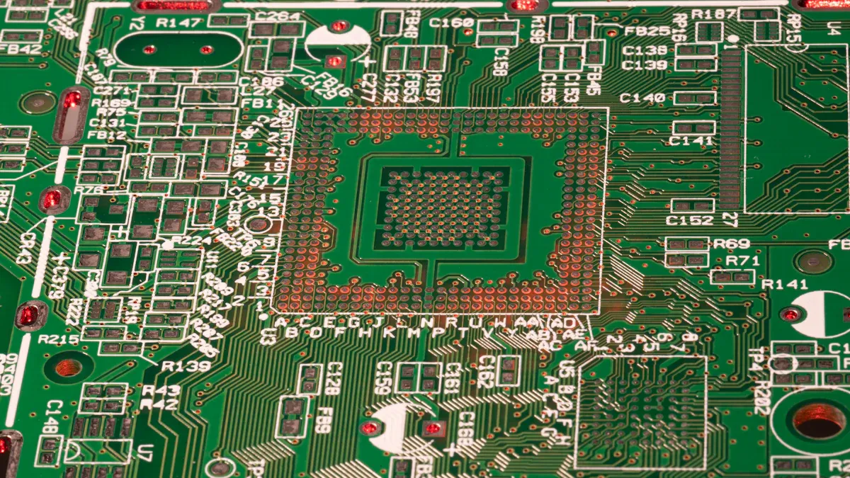
Silkscreen
The silkscreen is the top layer of PCBs. It has printed labels to show parts, test spots, and other details. These labels help you build, check, and fix the board. For example, part names and polarity marks help place parts correctly, reducing mistakes.
Silkscreens use clear, big text to make reading easy. This helps even beginners find and understand parts quickly. Standard labels also make checks faster and reduce errors. By giving quick info, silkscreens save time and ensure the board works right.
Silkscreens also make PCBs look better. They give a neat, professional look, which is important for gadgets people see and use.
Purpose of Each Material in Printed Circuit Boards
Conductive Layers (Copper)
Copper makes the conductive layers in PCBs. These layers let electrical signals move between parts. Without copper, signals wouldn’t travel properly.
Different conductive layers are used for various designs. Here's a simple table:
Type | Description |
|---|---|
Type 1 (Single Layer) | One layer of copper, either between two insulators or open on one side. Used for flexible or static boards. |
Type 2 (Double Layer) | Two copper layers with holes connecting them. Works for flexible or static boards. |
Type 3 (Multilayer) | Three or more copper layers with connecting holes. Common for static boards. |
Type 4 (Multilayer Rigid-Flex) | Three or more copper layers with connecting holes, mixing stiff and flexible materials. Fits many uses. |
Copper is tested to ensure it works well. For example:
TDR Impedance Testing checks if signals stay steady on copper paths.
Thermal Cycle Testing (TCT) tests how copper handles heat changes. It finds cracks or resistance issues. Thicker copper often passes these tests better.
Copper helps PCBs handle both electricity and heat well.
Insulating Layers (Fiberglass and Epoxy Resin)
Fiberglass and epoxy resin are the insulating layers in PCBs. They keep copper layers apart to stop electrical shorts.
Fiberglass, like FR-4, makes the board strong and stiff. It keeps the board steady even under pressure. Epoxy resin acts like glue, holding layers together tightly.
These materials also protect the board from damage. Fiberglass resists heat and water, making it useful in many devices. Epoxy resin adds extra protection from temperature changes or impacts.
Together, they make PCBs safe, strong, and long-lasting.
Protective Layers (Solder Mask and Silkscreen)
Solder masks and silkscreens protect PCBs. The solder mask covers copper paths, leaving only needed spots open for soldering. This stops solder from spreading and causing shorts.
Solder masks also shield copper from harm. They block moisture, dust, and rust, helping the board last longer. Advanced masks, like nano-filled ones, are tougher and handle heat better.
Silkscreens give helpful labels. They show part names and marks to guide assembly and repairs. Clear labels reduce mistakes and save time.
These layers make PCBs work better and look professional. A good PCB is reliable and neat for any use.
Layering Process of Printed Circuit Boards

Substrate and Core Layer
The substrate and core layer are the PCB’s base. The substrate is usually fiberglass sheets. These sheets are coated with copper foil using epoxy resin. This makes the PCB strong and dust-resistant.
The core layer gives the board its strength. It is made of epoxy resin and glass fiber. Copper foil is added to make it sturdy and stable.
Here’s a simple table about these layers:
Layer Type | Material Used | Description |
|---|---|---|
Core Layer | Epoxy resin and glass fiber | Makes the board strong and stable, with copper foil. |
Substrate | Fiberglass sheets | Creates a dust-resistant base for the PCB. |
Different PCBs use different substrates:
Rigid PCBs use hard fiberglass sheets.
Flexible PCBs use bendable materials.
Rigid-flex PCBs mix both for more uses.
Copper Foil Application
After the base layers are ready, copper foil is added. This creates paths for electricity to move through the PCB. Heat and pressure bond the copper foil to the substrate. This makes the connection strong and smooth for the next steps.
The copper foil’s thickness depends on the PCB’s job. Thick copper handles more current. Thin copper works for low-power devices. Good bonding stops peeling or electrical problems later.
Prepreg and Lamination
Prepreg and lamination join all PCB layers together. Prepreg is fiberglass with epoxy resin already on it. It sticks the copper foil to the core layer.
During lamination, layers are stacked in order. Heat and pressure harden the resin in the prepreg. This bonds the layers into one solid board.
Quality checks are important here:
Before lamination, materials and alignment are inspected.
During lamination, temperature and pressure are monitored.
After lamination, size and electrical paths are tested.
Temperature and pressure must be just right. They affect how well the resin hardens and layers stick. Clean surfaces are also key to avoid problems.
This process makes a strong PCB for many uses.
Solder Mask Coating
The solder mask is important for protecting a PCB. It keeps copper paths safe from damage and helps the board work well. This layer stops copper from rusting or breaking down, even in tough conditions.
Solder masks also stop electricity from jumping between copper paths. This lowers the chance of short circuits. This is very helpful in small designs where parts are close together. By keeping paths separate, the solder mask makes the board more reliable.
The solder mask also makes the board last longer. It blocks water, dust, and sunlight from harming the PCB. It also improves solder joints, so the board stays strong. Makers test solder masks for heat and moisture resistance to ensure they work well.
Here’s what solder masks do:
Stop rust and damage to copper.
Keep copper paths apart to avoid short circuits.
Make the board stronger and more reliable.
Tested to handle tough conditions.
Pick the right solder mask for your board. Regular ones are good for most uses. Nano-filled ones handle heat and fast signals better.
Silkscreen Printing
Silkscreen printing adds helpful labels to your PCB. These labels show part names, polarity marks, and test spots. They help you place parts correctly and avoid errors.
Clear silkscreen labels save time. They make it easy to find parts and fix problems. Even beginners can use these labels to build or repair boards confidently.
Silkscreens also make the board look nice. They give it a clean, professional appearance, which is great for gadgets people use.
To make good silkscreens, makers use strong inks and careful printing. This keeps the labels clear and lasting, even after lots of use.
Types of Printed Circuit Boards and Their Material Compositions
Single-Sided PCBs
Single-sided PCBs are the easiest type to make. They have one copper layer on one side for electricity flow. These boards are cheap and simple to produce, perfect for basic gadgets.
You can find single-sided PCBs in calculators, power supplies, and LED lights. They work well for devices that don’t need complex features.
In 2023, the market for single-sided PCBs was worth $2.5 billion. It may grow to $4.2 billion by 2032 due to demand in electronics and cars.
These boards are popular because they are affordable and effective. They are used in smartphones, tablets, and wearable devices.
Double-Sided PCBs
Double-sided PCBs have copper layers on both sides of the board. Small holes, called vias, connect the two sides for signal flow. This design makes them more useful than single-sided boards.
You’ll find double-sided PCBs in amplifiers, industrial machines, and HVAC systems. They are flexible and handle more advanced circuits.
Materials like FR-4 provide insulation, while copper ensures conductivity. These materials make the boards strong and dependable.
Multilayer PCBs
Multilayer PCBs have three or more layers of copper and insulation. These layers are pressed together with heat to form one compact board.
Multilayer PCBs are used in high-tech devices like satellites, medical tools, and communication systems. For example:
A satellite PCB for a 10-year space mission uses multilayer design for heat control and durability.
Airplane control systems depend on multilayer PCBs for safety and signal accuracy.
The materials in multilayer PCBs depend on their use. Polyimide is common in aerospace because it resists heat well. The chart below shows materials used in different PCB types:
Multilayer PCBs are dense and compact, making them key for modern devices.
Flexible PCBs
Flexible PCBs can bend and twist, making them useful for moving parts. They use materials like polyimide or polyester film instead of hard fiberglass. These boards fit into small spaces, perfect for wearables, cameras, and medical devices.
Flexible PCBs have pros and cons. Here's a simple table:
Advantages | Challenges |
|---|---|
Saves Space and Weight | Higher Cost |
Better Reliability | Harder to Design |
Easier Assembly | Fewer Component Choices |
Handles Movement | Needs Precise Manufacturing |
Manages Heat Well | N/A |
These boards save space and weigh less. They are reliable because they don’t need extra connectors or cables. Assembly is easier, and they work well with moving parts. But designing them is tricky, and they cost more to make.
Flexible PCBs are tested to ensure they last in tough conditions. Bend tests check if they can flex many times without breaking. These tests prove they work well in foldable phones or robotic arms.
Tip: If your project has tight spaces or moving parts, flexible PCBs are a smart choice. They simplify designs and still perform well.
Rigid-Flex PCBs
Rigid-Flex PCBs mix strong and bendable parts. The rigid sections add strength, while the flexible parts allow movement. This makes them great for devices needing both, like aerospace tools or medical implants.
These boards are more reliable than regular ones. They replace wires and cables, cutting costs but keeping performance high. Their strength ensures they last a long time in electronic devices.
Rigid-Flex PCBs are made for top performance and tested carefully.
Tests like bend cycles and heat checks show they handle real-world use.
They resist things like temperature changes, moisture, and physical stress.
Here’s how they are tested:
Engineers check electrical, mechanical, and structural performance.
Advanced tests ensure they work in different conditions.
Designs are made to handle tough environments.
Rigid-Flex PCBs are perfect for devices needing both flexibility and strength. They are trusted in industries like cars and defense because they last in harsh conditions.
Note: If your device needs to be strong and flexible, Rigid-Flex PCBs are a dependable choice.
Printed circuit boards are made using materials like copper, fiberglass, epoxy resin, solder mask, and silkscreen. Each material has a special job to help the board work well and last long. Copper carries electricity, while fiberglass adds strength and keeps electricity from leaking. The layering process, including lamination and solder mask application, makes the board strong and dependable in different situations.
Design updates solve problems like electromagnetic interference and high-current paths. For example, keeping sensitive parts apart and using wider copper areas instead of thin lines improves performance. New ideas like via-in-pad designs and materials with low dielectric constants make signals faster and more reliable. These changes help printed circuit boards work in many devices, from phones to airplanes.
Problems | Fixes |
|---|---|
Electromagnetic Interference | Keep inductors away from sensitive parts like microcontrollers. |
High-Current Paths | Use wide copper areas instead of thin lines for better flow. |
Microcontroller Layout | Place parts smartly and use inner layers for signal paths. |
Key Improvements | Details |
|---|---|
Via-in-Pad Design | Makes solder pads better for tiny parts. |
Better Materials | Uses materials that improve signal speed and reduce loss. |
Performance Testing | Proves the board works well with fast digital signals. |
By using strong materials, careful layering, and smart designs, printed circuit boards can handle the needs of today’s technology.
FAQ
What does a printed circuit board (PCB) do?
A PCB links electronic parts with conductive paths. It holds and organizes these parts, helping signals move smoothly. This makes devices like phones, computers, and appliances work well.
Why is copper important in PCBs?
Copper carries electricity very well. It lets signals move fast with little resistance. Copper also spreads heat efficiently, making PCBs strong and reliable.
How do solder masks keep PCBs safe?
Solder masks protect copper paths from water, dust, and rust. They stop solder from spreading to wrong spots, lowering the chance of short circuits. This keeps the board working properly.
Can PCBs handle high heat?
Yes, PCBs use heat-resistant materials like FR-4 and epoxy resin. Special designs with high-Tg solder masks or polyimide layers can handle very high temperatures in tough jobs.
How are flexible PCBs different from rigid ones?
Flexible PCBs use bendable materials like polyimide. They can fit into small spaces or moving parts. This makes them great for wearables, cameras, and medical tools.
See Also
Exploring PCB Printed Circuit Boards And Their Key Principles
Defining Multilayer PCBs And Their Role In Electronics
Exploring Rogers R4350B R4003 R5880 For RFPCB Applications
