PCB Stators for Drones and UAV Motors
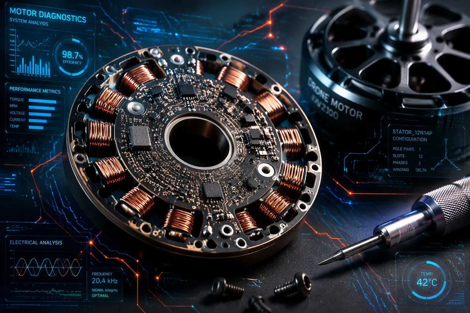
PCB stators take the place of traditional stator cores in brushless motors. Engineers build these stators on printed circuit boards instead of laminated steel. This design cuts stator weight by up to 80 percent. The weight reduction lets a drone motor run longer on the same battery. Drone designers use this technology because it is compact and flexible in design. A single drone pcb can hold the whole motor structure. This approach makes manufacturing simpler for small UAV platforms. However, this design has limits. Torque density drops compared to traditional stators. Thermal management also needs careful planning. Engineers must weigh these trade-offs for their specific drone application.
Key Takeaways
PCB stators replace heavy steel cores with lightweight circuit boards. This cuts stator weight by up to 80 percent. Drones fly longer on the same battery.
Printed copper traces act as motor coils. This design removes hand-wound coils. Manufacturing becomes simpler and more consistent.
PCB stators save space and improve efficiency. They fit into tight airframes. They turn more power into thrust and less into heat.
Traditional stators still offer higher torque and better heat management. PCB stators work best for small to mid-size drones. Designers should match the stator to the mission.
A single drone PCB can hold both the stator and the ESC. This integration reduces cables and failure points. It makes the propulsion system more compact.
How PCB Stators Work in UAV Motors
A PCB stator swaps out big copper windings for a very thin printed circuit board. The board has copper traces that work as the motor coils. Current moves through these traces and makes a spinning magnetic field. This field turns the rotor. The design gets rid of hand-wound coils and laminated steel cores. Engineers can now see the stator as one electronic part.
Drone Motor Stator Winding on a PCB
The drone motor stator winding process changes fully with printed circuit boards. Instead of wrapping copper wire around teeth, designers put copper traces right onto the board. These traces make the coils that create torque. The stator windings lie flat on the PCB surface. This layout gives exact control over trace width, spacing, and layer count.
Motor CAD tools make this process quick and repeatable. PrintStator, for example, lets engineers enter form factor limits, efficiency goals, torque, and power needs. The software then creates an optimized PCB stator design in about one second. That result stays accurate to within one to two percent of measured performance. Optimization algorithms cut a month-plus process down to seconds. A full custom motor design goes from idea to working hardware in weeks, not months.
The software outputs a Gerber file with copper weight, layer layout, vias, solder mask, and legend details. PCB manufacturers around the world can print this file right away. This workflow removes the tooling delays common with custom brushless drone motor stator cores. Engineers iterate by re-entering changed parameters and generating a new design in hours.
Rotor Integration and Motor Assembly
The stator joins with the rotor and the rest of the motor assembly through a simple mechanical stack. The PCB stator mounts inside the motor housing. The rotor holds permanent magnets and spins around or beside the stator. Motor phase outputs connect the stator traces to the drive electronics. These motor phase lines carry current from the ESC to the coils.
A drone pcb can hold the motor control circuitry on the same board as the stator. This integration puts the ESC, sensors, and motor phase lines on one substrate. Designers then manage power integrity in drone pcbs alongside motor timing. High-current motor traces need careful width and copper weight choices. These choices affect heat buildup and voltage drop.
The assembly process itself is simple. A partner using ECM's vertical integration model runs a six-step assembly process with a two-person, two-shift team. That team forecasts about 200,000 motors per year. The stator arrives as a finished PCB. Workers stack the rotor, bearings, and housing around it. This approach removes the winding step entirely. It also cuts assembly time and reduces differences between units.
Printed stators also handle tough use. Motors built this way have reached 30,000 RPM in drone applications. The drone stator works as a reliable, repeatable part rather than a handcrafted assembly.
Key Benefits for Drone PCB Motors
Weight, Size, and Efficiency Gains
Weight is the first thing drone designers notice. A PCB stator removes the heavy laminated steel core and the copper wire bundle. This change cuts stator weight by up to 80 percent. Less weight means the drone motor needs less power to stay in the air. The same battery then flies the aircraft for a longer time.
Size shrinks along with weight. A thin circuit board takes far less space than a stack of steel laminations. Engineers can fit the motor into tight airframes. They can also place the motor closer to other electronics. This freedom opens new shapes for small UAV platforms.
Efficiency improves in a related way. Copper traces on a board follow a precise path. That path lowers resistive losses compared to a hand-wound coil. The motor turns more of its input into thrust and less into waste heat. A drone that runs cooler can also run longer.
These gains matter most for small aircraft. A tiny quadcopter has little room and little lift to spare. Every gram counts. PCB stators give designers a way to save that weight without giving up performance.
Reliability and the Drone Motor Winding Manufacturing Process
The drone motor winding manufacturing process changes completely with printed boards. Traditional motors need a worker to wrap copper wire around each tooth by hand. That step takes time and invites mistakes. A printed stator replaces the wire with copper traces. A machine prints those traces with the same accuracy every time.
This consistency pays off in the field. Motors built this way have reached 30,000 RPM in drone applications. Those numbers show that a printed stator can handle real flight conditions. The part does not loosen or shift the way a hand-wound coil can.
Assembly costs drop as well. Workers no longer wind coils. They stack the rotor, bearings, and housing around a finished board. This step removes a slow, skilled task from the line. It also cuts the number of parts and the complexity of the build.
The drone pcb manufacturing process fits this model well. A single board can carry the stator windings and the drive electronics. Designers then treat the motor as one electronic part. This approach reduces differences between units. Every motor from the line behaves the same way.
Reliability also comes from fewer failure points. A hand-wound coil can break, short, or rub against the core. Printed traces stay fixed in place. They resist vibration and shock better than loose wire. For a drone that must fly in wind and turbulence, that matters.
PCB Stators vs. Traditional Stators
Construction and Material Differences
A traditional build uses laminated silicon steel sheets for the stator. High-purity copper wire wraps around the core teeth to form the stator windings. The winding layout determines motor power output. Engineers adjust coil turns and wire diameter for target torque. The core design directly influences torque output and energy efficiency. Custom designs adjust slot geometry and lamination thickness. This construction needs skilled labor.
PCB stators replace the steel core with a printed circuit board. Copper traces on the board act as the coils. A drone pcb design places these traces in a flat, wide geometry. The stator supports an axial-flux motor arrangement. The wide profile delivers greater torque leverage. The drone pcb follows a simple fabrication step. Workers avoid winding wire. The result is a lighter stator that fits compact drone airframes.
Performance Trade-Offs and Best Uses
Traditional designs produce high torque at low speeds but need gear reduction. Cogging creates torque ripple. The planar geometry reduces cogging. These traits suit precise motion. The motor offers physics-driven stability. It supports an IIMS architecture. No gear reduction cuts weight.
Thermal behavior differs. A traditional motor manages heat through the steel core. The board spreads heat across the surface but lacks thermal mass. Engineers consider this limit for high-power use. Laminated cores provide durability during thermal cycling.
Each design wins in specific areas. Traditional builds work for high-torque drone applications. They fit drone platforms where weight is less critical. The drone motor stator winding process disappears with PCB technology. A designer evaluating a drone pcb for propulsion weighs torque against weight. The axial-flux design works with drone pcbs, enabling integrated electronics. Engineers use this for drone motor designs that prefer compact size. The design enables new airframe shapes. PCB motors deliver torque efficiently, reducing waste from heat and corrective effort. They support field serviceability and predictable thermal behavior. Traditional bldc motors remain better for high-power needs. A PCB motor makes efficient use of available power.
Applications and Selection Tips
Drone PCB Integration in Multirotor and Fixed-Wing UAVs
The ECM Quadcopter Drone Lift Motor shows how pcb stators work in real flight hardware. This motor uses a printed stator to lower weight and open up room inside the airframe. Multirotor designs gain the most since they carry several motors. Every gram saved on a stator adds up across the frame. Fixed-wing UAVs also benefit from the thin shape. A slim stator fits inside narrow wings and fuselage sections.
Engineers can put the electronic speed controller on the same drone pcb as the stator. This step places motor control and power switching on one board. The propulsion system then gets even smaller. A drone circuit board that holds both the stator and the drive electronics removes cables and connectors. That change lowers weight and failure points at the same time.
Tiny quadcopters and miniaturized UAVs gain the most from this method. A designer can add a motor to a larger drone pcb design at low cost. The motor turns into one more component on the board. This method fits custom drone pcb development for small platforms. It also helps teams that build many units on a tight budget.
Performance Factors and Limitations to Consider
Engineers must weigh two main limits before picking pcb stators for a drone motor. Thermal management sits at the top of the list. Higher-flux magnets tend to lose their magnetism at lower temperatures. Heat buildup becomes critical as power demands go up. High-power applications need proper cooling to stop magnet demagnetization.
Torque output is the second limit. Triangular coil shapes maximize stator flux area. That shape gives fewer turns per layer, about seven. Fewer turns lower winding impedance. Lower impedance causes more heating. This heating limits achievable torque and calls for thermal management. The trade-off matters more for larger PCB motors.
A uav stator built this way still fits many missions. Small drones with modest power needs see clear gains. Larger platforms that need high torque may favor traditional brushless dc motors. Designers should match the stator type to the mission profile. They should also plan cooling paths early. A drone that flies light and cool will beat one that pushes a stator past its thermal limit.
PCB stators replace steel cores and hand-wound coils with copper traces on a circuit board. They work as flat motor coils that spin the rotor. They cut weight by up to 80 percent, save space, and simplify assembly. Traditional stators still win on torque density and thermal mass. For many drones, the weight and efficiency gains matter more. A drone pcb can hold the stator and the ESC together. Designers should check their power needs and cooling limits first. The drone motor field keeps moving toward lighter, integrated propulsion. As drone pcb designs mature, printed stators will likely power more UAV platforms.
FAQ
How long does a PCB stator motor typically last in flight?
The PCB stator gets rid of hand-wound coils that can come loose over time. Motors with printed stators have hit 30,000 RPM in drone use.
Can a PCB stator motor handle high power for large drones?
PCB stators work best in small to mid-size drones. Big platforms that need high torque still rely on traditional stators. The weight savings matter most in compact frames.
How does a designer integrate the PCB stator with the ESC?
A single drone pcb can hold both the motor coils and the electronic speed controller. This setup removes extra cables and connectors. The propulsion system becomes more compact.
How quickly can an engineer create a custom PCB stator design?
Motor CAD tools like PrintStator make an optimized design in about one second. The software puts out a Gerber file that is ready to build. A custom design goes from idea to hardware in weeks.
See Also
Discovering The Raw Materials That Printed Circuit Boards Are Made Of
How Multilayer PCBs Are Used Across Different Industries Today
Best Methods To Reduce Back Drilling Costs In HDI PCB Boards
Which Type Of PCB Is Best Suited For ATE Challenges?
Rigid PCB Production: Materials, Processes, And Quality Standards For Industrial Use
