Precautions for the design of PCB circuit boards
Designing PCB circuit boards requires careful planning for optimal performance.
Choose the right materials and connect wires accurately.
These steps prevent mistakes and enhance the functionality of the board.
They also ensure compliance with industry regulations and standards.
By concentrating on these aspects, you can create robust and effective boards.
Key Takeaways
Pick good materials for PCB boards to improve performance. Quality materials stop overheating and meet safety rules.
Place parts correctly and leave enough space between them. Keep similar parts together to avoid problems and make assembly easier.
Test your PCB carefully to make sure it works well. Check signals often and follow industry rules for better designs.
Material Selection for PCB Circuit Boards
Picking the Best Materials for Good Performance
Choosing the right materials for PCB boards is very important. You should think about how well they conduct electricity, handle heat, and stay strong. Some uses need materials that work well with high-speed signals and manage heat properly. For example, PTFE and ceramic-filled laminates are great for aerospace and cars because they handle heat and electricity well.
Good material choices also make boards safer and more reliable. The Comparative Tracking Index (CTI) shows how well a material resists things like moisture and chemicals. Materials with higher CTI values are safer and last longer in tough conditions. Picking the right materials helps the board work better and meet safety rules.
Important Properties to Check
When making PCB boards, check how materials handle heat, electricity, and stress. Managing heat well stops parts from overheating and breaking. Too much heat can cause problems, so pick materials that spread heat out well.
Electrical performance matters too. Materials that keep signals clear and steady are needed for fast boards. They help the board work well even in tough places. Strong materials are also important. They should resist things like shaking and temperature changes to last a long time.
Metric | What It Means |
|---|---|
Electrical Performance | Clear signals and steady operation for fast PCBs. |
Thermal Management | Spreads heat well to stop damage and make parts last longer. |
Mechanical Durability | Stays strong against shaking and temperature changes for long use. |
Balancing cost and quality is key. High-quality materials may cost more, but they are worth it for better performance and reliability.
LT CIRCUIT's Top PCB Material Choices
LT CIRCUIT has many great materials for different needs. Whether you need HDI boards or complex designs, LT CIRCUIT offers materials that handle heat, electricity, and stress well. These materials help boards work well even in hard conditions.
LT CIRCUIT uses the latest technology to improve their products. They use special laminates and finishes like ENIG and HASL to make boards stronger and better at conducting electricity. You can also customize your board with options like different solder mask colors and testing services. By picking LT CIRCUIT, you get high-quality materials that make sure your boards work well for a long time.
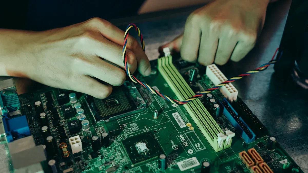
Component Placement and Layout in PCB Circuit Boards
Tips for Arranging Components
Placing components correctly helps with assembly and performance. Group similar parts together to make testing and assembly easier. Aligning parts properly avoids mistakes during production. For example:
Correct alignment stops size and shape mismatches.
Grouping similar parts improves function and lowers costs.
Good placement boosts performance in small designs.
Proper arrangement saves time and money. Following these tips makes boards easier to build and test.
Keeping Enough Space and Avoiding Problems
Spacing between parts is important for safe and smooth operation. Keep at least 2.5mm between connections and metal parts to avoid issues. For power parts and high-voltage areas, leave at least 4mm to stop electrical sparks. Proper spacing of traces prevents short circuits and keeps signals clear. These rules help your PCB boards work safely and well.
Power and Ground Plane Design Tips
Good power and ground planes make your PCB more stable. Close power and ground planes add extra capacitance, helping with high-frequency tasks. A 4-layer PCB should have one layer for the ground plane. Connect all circuit ground pins to this low-impedance plane to reduce noise. These tips keep signals strong and lower impedance, making your boards more dependable.
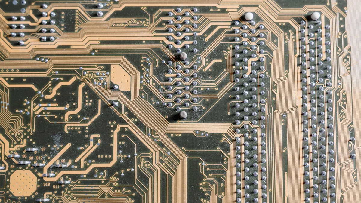
Wiring and Routing Techniques for PCB Circuit Boards
Managing High-Frequency Signals
To handle high-frequency signals, you need careful planning. Route clock lines at right angles to signal lines to stop crosstalk. Use fly-by topology in DDR4 designs to reduce reflections and boost performance. Keep loop areas small to avoid noise. Place decoupling capacitors near supply pins to block high-frequency noise.
For better shielding, use transmission lines like microstrip or stripline. Avoid FR4 material for high-frequency tasks because it loses too much signal. Follow the 20H rule by making the power plane 20% smaller than the ground plane. This absorbs extra fields and reduces interference. These steps help your PCB work well with high-frequency signals.
Routing Differential Pairs and Matching Impedance
Differential pair routing helps keep signals clear and strong. Keep the spacing between pairs even to reduce noise. Match trace lengths within the allowed limit to avoid timing problems. Proper impedance matching stops signal reflections and improves power transfer.
Differential signaling standards give rules for single-ended and differential impedance. Following these rules ensures better performance. Keeping spacing and length consistent reduces signal loss and makes your PCB more reliable.
Preventing Crosstalk and Signal Problems
Crosstalk can mess up signals and lower PCB performance. To prevent this, leave enough space between traces and use ground planes wisely. A good stack-up design separates signal layers and cuts down on interference. Placing signal layers next to ground or power planes gives stable paths for high-speed signals.
Factor | What It Does |
|---|---|
Trace Impedance | Keeps signals steady and reduces reflections. |
Trace Spacing | Stops signals from interfering with each other. |
Signal Reflection | Prevents signal distortion by keeping trace width consistent. |
Trace Coupling | Avoids unwanted interactions between nearby traces. |
Differential Pair Signaling | Cancels noise and keeps signals clear. |
By using these tips, you can improve signal quality and make your PCB work better.
EMI/EMC Considerations in PCB Circuit Boards
Reducing Electromagnetic Interference
Electromagnetic interference (EMI) can harm how your PCB works. To reduce EMI, lower noise and control signal paths. Keep fast signal lines short and far from sensitive parts. Place decoupling capacitors near power pins to block high-frequency noise.
Put ground planes close to signal layers to absorb interference. Use transmission lines like microstrip or stripline to keep signals clear. For high-frequency designs, avoid sharp trace angles. Sharp angles can reflect signals and increase EMI.
Tip: Route fast signals at right angles on nearby layers. This lowers crosstalk and boosts performance.
Best Ways to Shield and Ground
Good shielding and grounding protect PCBs from EMI. Follow these tips:
Use metal mesh or elastomer for shielding. These materials block outside noise and keep signals clear.
Add a ground on the PCB edge to make a Faraday cage. This blocks noise and limits emissions.
Connect device grounds straight to the ground plane. This avoids ground loops and makes the board stable.
If no ground layer exists, use ground grids. Grids give a low-impedance path for return currents.
Keep return paths short to lower impedance and improve EMC.
Using these methods reduces EMI and helps your PCB work well in different places.
Meeting EMI/EMC Standards
Following EMI/EMC rules makes your PCB safe and reliable. Testing checks how your design works in various conditions. Common tests include:
Type of Test | What It Checks |
|---|---|
Measures electromagnetic waves from the device. | |
Conducted emissions | Checks EMI passing through cables. |
Electrostatic discharge (ESD) | Tests if the device can handle static electricity. |
Voltage dips and interruptions | Checks how the device handles power drops. |
These tests find problems and help fix them. Meeting standards ensures safety and better product reliability.
Note: LT CIRCUIT offers testing services to meet EMI/EMC rules. Their expertise ensures top-quality designs.
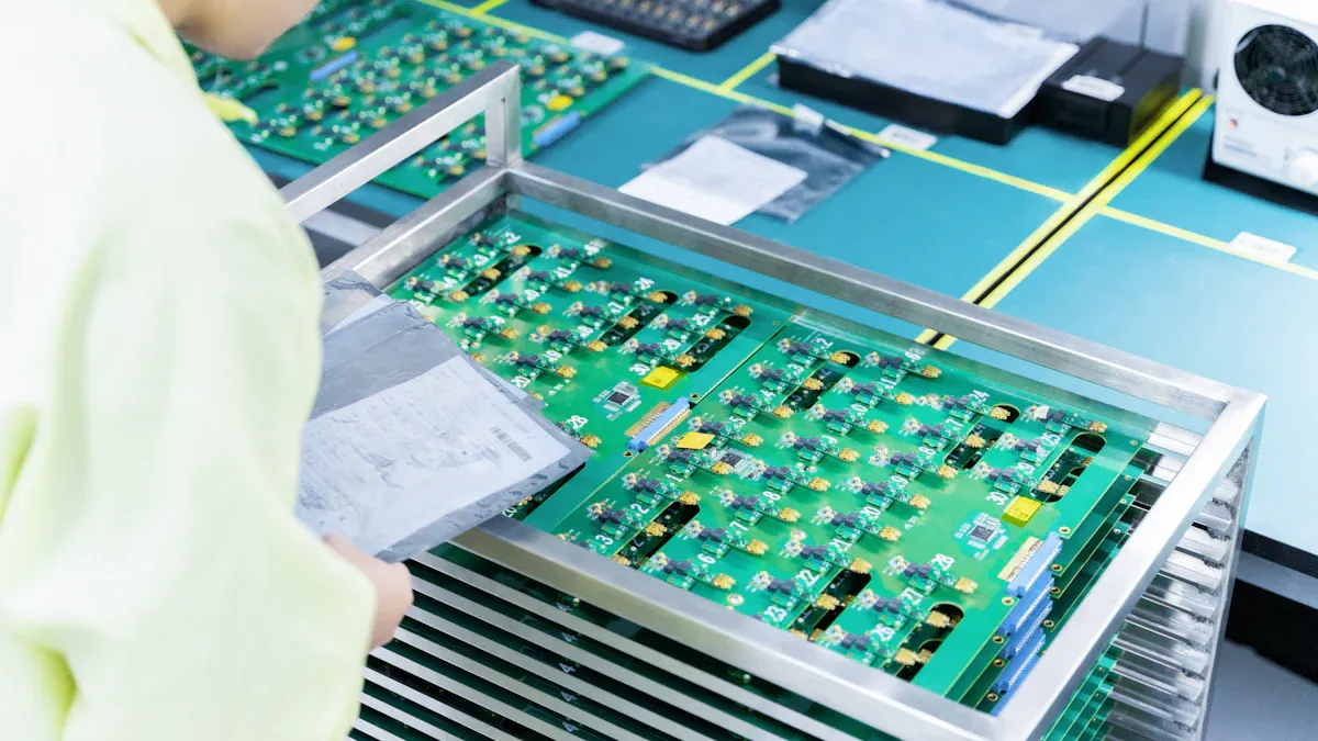
Testing and Verification of PCB Circuit Boards
Checking Signals for Reliable Performance
Testing signals makes sure your PCB works well. Mechanical tests, like vibration and shock checks, test strength. Shock tests find problems like cracks or broken parts. Electrical tests check insulation and connections to avoid short circuits.
For high-frequency boards, tests measure signal loss and interference. Tools like oscilloscopes help analyze these issues. Timing and clock design are also tested to keep signals clear. These steps ensure your PCB works in tough conditions without failing.
Testing How the PCB Works Over Time
Functional tests check if your PCB works for a long time. These tests copy real-life conditions to find problems early. For example, thermal tests heat and cool the board to check for damage. Power tests turn the board on and off repeatedly to see if it lasts.
These tests help find weak spots and improve the design. This makes the PCB more reliable and last longer. Functional testing is key to making sure your PCB meets user needs and works well over time.
Meeting Rules and Getting Certified with LT CIRCUIT
Compliance tests make sure your PCB follows important rules. LT CIRCUIT uses global certifications to ensure quality. These include:
Certification/Standard | What It Does |
|---|---|
Sets rules for making and designing PCBs. | |
UL | Tests PCB materials and parts for safety. |
ISO | Gives advice on managing quality in PCB production. |
IEC | Creates rules for electrical technologies. |
RoHS | Bans harmful substances in electronics. |
WEEE | Encourages recycling and less electronic waste. |
REACH | Controls chemical use in PCB making. |
QS certification | Checks if quality standards are followed. |
By following these certifications, LT CIRCUIT ensures safe and high-quality PCBs. Their testing makes sure your boards meet rules and work reliably.
Creating PCB circuit boards carefully makes them work better and last longer. Using good materials, placing parts correctly, and wiring properly avoids expensive fixes. Testing early finds problems and saves time. Reliable power helps the board run smoothly and lowers mistakes. Following rules ensures your designs meet standards and succeed over time.
FAQ
What matters most in PCB design?
Picking the right materials is very important. It affects how well the board handles heat, works with electricity, and stays strong. Use materials that fit your project to make it reliable and efficient.
How do you stop signal problems in PCB designs?
Keep enough space between traces, use ground planes, and add shielding. These steps help avoid crosstalk and electromagnetic interference, keeping signals clear and steady.
Tip: Test your PCB for signal issues early to fix problems fast.
Why is testing important for PCB boards?
Testing checks if your PCB works safely and properly. It finds design mistakes, makes the board more reliable, and ensures it follows industry rules.
Note: LT CIRCUIT provides full testing services to ensure top-quality boards.
See Also
Essential Skills For Designing Multi-Layer PCB Layouts Effectively
Challenges In Manufacturing And Prototyping Multi-Layer Circuit Boards
Understanding The Components That Form Printed Circuit Boards