The production process of multilayer rigid-flex circuit boards
Understanding the production process of multilayer rigid-flex boards reveals their exceptional quality. These boards play a crucial role in today's electronics and devices. Familiarity with their production process benefits both experts and hobbyists alike. LT CIRCUIT excels in creating robust, high-quality PCBs, offering innovative solutions for a variety of applications.
Key Takeaways
Multilayer rigid-flex boards mix stiff and bendable parts. They are great for small and strong electronic gadgets.
These boards are now common in fields like space and healthcare. This is because they work well and handle harsh environments.
Picking rigid-flex boards saves room and weight. They last longer and cost less over time, even if they cost more to make at first.
Overview of multilayer rigid-flex circuit boards
What are multilayer rigid-flex circuit boards?
Multilayer rigid-flex boards mix rigid and flexible PCB features. They have many conductive layers connected by vias and bonded together. These boards include stiff parts for support and flexible parts for tight spaces or movement. Their special design helps make small, light, and reliable electronic devices.
The technical details of these boards depend on their use. For example:
Specification | Details |
|---|---|
Layer Count | 1-6L (Flex), 2-10L (Rigid-flex) |
Base Polyimide Film Thickness | 0.5 mil (12.5µ), 1 mil (25µ), 2 mils (50µ) |
Copper Thickness | 1/3oz (12µ), 1/2oz (18µ), 1oz (35µ), 2oz (70µ) |
These features make them important for advanced electronics.
Applications in industries like aerospace, medical, and consumer electronics
Multilayer rigid-flex boards are used in industries needing high performance. In aerospace, they work in navigation and communication devices under tough conditions. In medicine, they power pacemakers and imaging tools where size and accuracy matter. Consumer electronics use them in phones, wearables, and gaming devices.
The demand for flexible PCBs is growing fast. For example:
The global flexible PCB market may grow from $21.01 billion in 2023 to $76.49 billion by 2033, with a 13.79% yearly growth rate.
Multilayer FPCBs are growing fastest due to compact and flexible device needs in healthcare, cars, and electronics.
Benefits of rigid-flex PCBs over traditional PCBs
Rigid-flex PCBs have many advantages over regular PCBs. They remove the need for big connectors and cables, saving space and weight. This design also makes them more reliable by reducing weak points. For example:
Rigid-flex PCBs weigh only 10% of similar wired solutions.
Fewer solder joints mean better durability under stress.
They also save money over time. While they cost more to make, they cut assembly time and repair costs. They handle heat and stress better, making them great for tough jobs.
Choosing rigid-flex PCBs gives you a strong, flexible, and efficient option for modern electronics.
Step-by-step production process by LT CIRCUIT
Design and layout creation
The process starts with planning the board's design. The design must meet the needs of the device. Vias need careful placement, especially in flex areas. Keep at least 20 mils between a via’s copper edge and the rigid-flex joint.
To make a strong design, use advanced software like:
Altium Designer: Combines tools for 3D designs.
KiCAD, OrCAD, Allegro, and Eagle: Help with routing and design rules.
These programs improve the design for better performance and reliability.
Material selection and preparation
Picking the right materials is key for a durable board. LT CIRCUIT uses top-quality materials that meet industry rules. Below are important material features:
Feature | Details |
|---|---|
Great for fast devices; thinner and more reliable. | |
Copper thickness | Minimum 0.25 oz for flexibility; maximum 2 oz. |
Polyimide coverlay | Even thickness boosts strength and performance. |
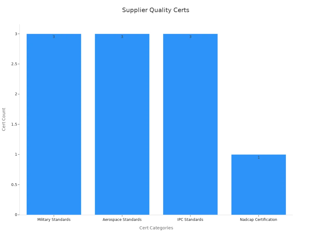
LT CIRCUIT follows strict certifications like IPC-6012 and AS9100 for trusted materials in aerospace and medical fields.
Fabrication of rigid and flexible layers
Making the rigid and flexible layers involves careful steps:
Add adhesive or coating for plating.
Attach copper foil using lamination or chemical plating.
Drill holes with machines or lasers for accuracy.
Flexible layers use materials like polyimide and PET films. Copper is etched to form patterns using special techniques. These steps keep rigid and flexible parts separate but strong.
Lamination and bonding of layers
Lamination joins rigid and flexible layers into one board. Alignment is crucial to avoid mistakes. LT CIRCUIT uses advanced methods for strong bonding. Polyimide coverlays add strength, while adhesive-less materials improve flexibility. This step ensures the board handles stress and heat well.
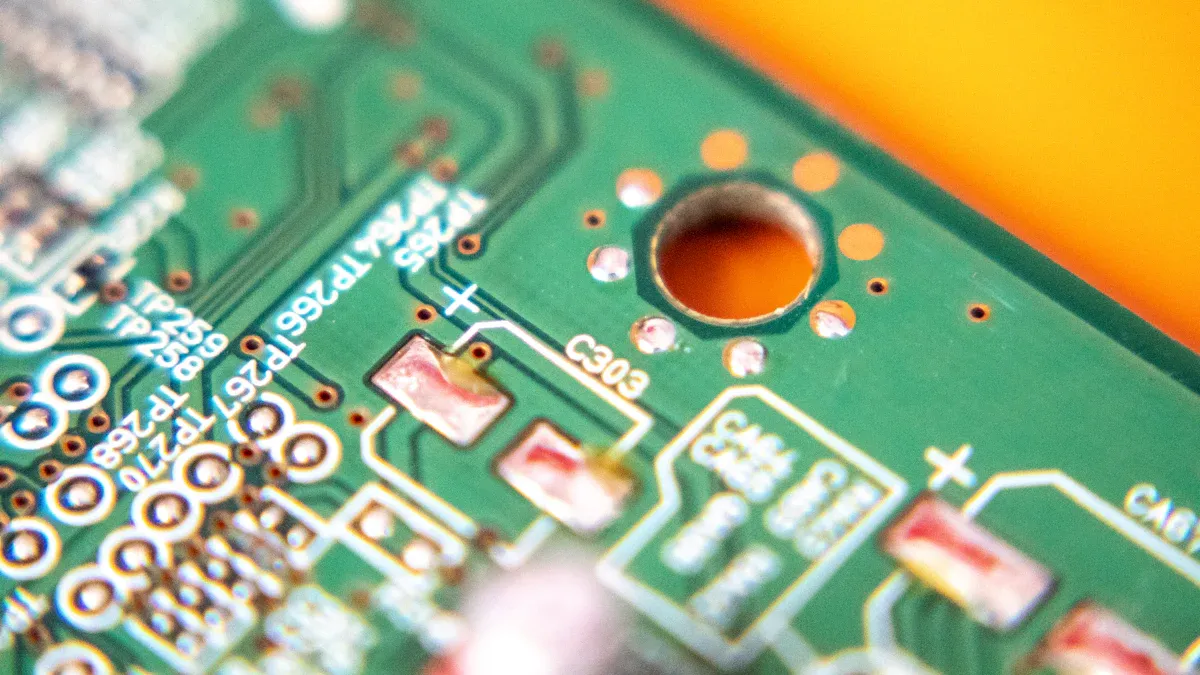
Drilling, plating, and etching
Drilling makes holes to connect layers. LT CIRCUIT uses machines and lasers for precision. Copper is added to the holes using a chemical process.
Etching removes extra copper to shape the circuit paths. Chemicals are carefully controlled to make accurate designs.
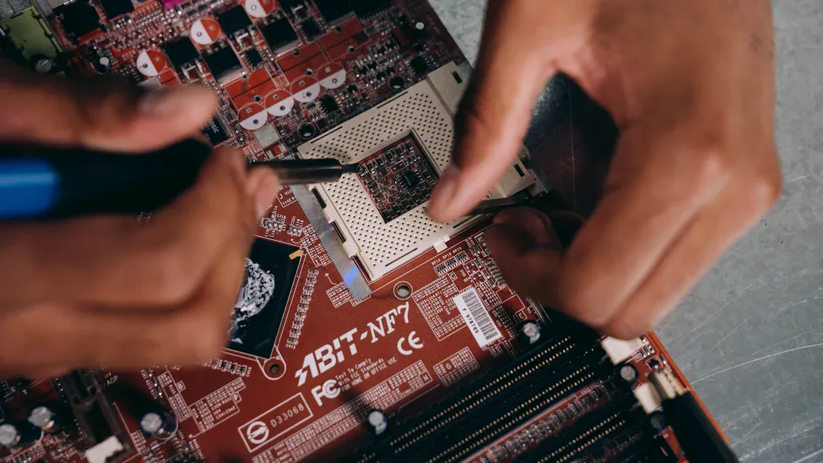
Assembly and component placement
After making the board, components are added and soldered. Machines place parts accurately to avoid errors. LT CIRCUIT uses advanced soldering to secure parts and ensure good connections. This step turns the board into a working device.
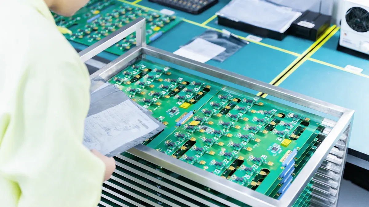
Testing and quality assurance
Testing is the last step in making the board. LT CIRCUIT uses strict checks to meet industry standards. Below are testing methods:
Test Type | Class 1 | Class 2 | Class 3 |
|---|---|---|---|
Electrical continuity and isolation | Basic pass/fail checks. | Tighter rules with records. | No defects allowed. |
Thermal cycling and environmental stress | Fewer cycles at lower heat. | More cycles at higher heat. | Tough tests with fast cycles. |
Mechanical bending and flexibility | Minor wear is okay. | No visible damage allowed. | No cracks or peeling. |
Adhesion test (Peel strength) | Some peeling is fine. | Strong bonding needed. | Maximum strength required. |
Machines check for visual flaws automatically. LT CIRCUIT also tests heat resistance and voltage strength. These checks ensure the board is tough and reliable.
Challenges and solutions in the production process
Handling heat and stress issues
Heat and stress can damage rigid-flex circuit boards. Temperature changes make materials expand or shrink, causing cracks. To fix this, use tools like thermal vias or heat sinks. These spread heat evenly and lower stress on the board. Simulation tools can predict heat effects and improve designs before making the board.
Evidence Type | Description |
|---|---|
Thermal Management | Tools like thermal vias or heat sinks reduce heat stress. |
Simulation Tools | Simulations predict heat effects and improve designs early. |
Using these methods keeps the board strong in different conditions.
Keeping layers aligned during lamination
Aligning layers perfectly is key for multilayer PCBs to work. Misaligned layers can cause poor performance or failures. Follow good design rules and use automated machines to avoid mistakes. Design for Manufacturability (DFM) ensures tight tolerances. Careful handling also prevents stress and keeps layers aligned.
Layers must align perfectly for good electrical connections.
Automated machines reduce errors and improve accuracy.
These steps ensure the layers stick together and work well.
Solving testing and inspection problems
Testing is important to make sure rigid-flex PCBs work well. But testing these boards can be hard because they are complex. Use tests like stress screening and burn-in testing to find problems. Automated systems help spot flaws quickly and accurately.
Problems like interference need advanced testing to fix.
Strict quality checks are needed since small flaws can fail.
Thorough testing ensures the boards are reliable and perform well.
Making multilayer rigid-flex boards needs careful steps, like design and testing. Every step helps make the boards strong and work well. LT CIRCUIT uses top tools and follows strict rules to stand out.
Working with LT CIRCUIT means you get trusted circuit boards. Their skill ensures your devices are modern, strong, and work great.
Pick LT CIRCUIT for smart and reliable solutions.
FAQ
Why are rigid-flex PCBs better than regular PCBs?
Rigid-flex PCBs are strong and flexible. They take up less space, weigh less, and work better by removing big connectors and wires. This makes them perfect for small, powerful gadgets.
How does LT CIRCUIT check the quality of rigid-flex PCBs?
LT CIRCUIT uses special tests like heat cycling, bending checks, and machine inspections. These tests make sure the boards are tough and meet strict rules for performance.
Can rigid-flex PCBs survive in tough conditions?
Yes! Rigid-flex PCBs can handle heat, pressure, and shaking. Their design and materials make them great for hard jobs in aerospace, medical, and industrial fields.
💡 Tip: Always ask your maker about your project's needs for tough conditions.
See Also
Exploring The Structure And Function Of Rigid-Flex PCBs
The Components That Make Up Printed Circuit Boards
Essential Skills For Designing Multi-Layer PCB Layouts
The Role Of Multilayer PCBs In Modern Electronic Devices
Utilizing Horizontal Copper Sinking Technology In PCB Manufacturing