Understanding the dielectric constant of Rogers PCB boards
Rogers PCB materials feature a dielectric constant range from 2.2 to 11, as highlighted in recent datasheets with specific values shown below:
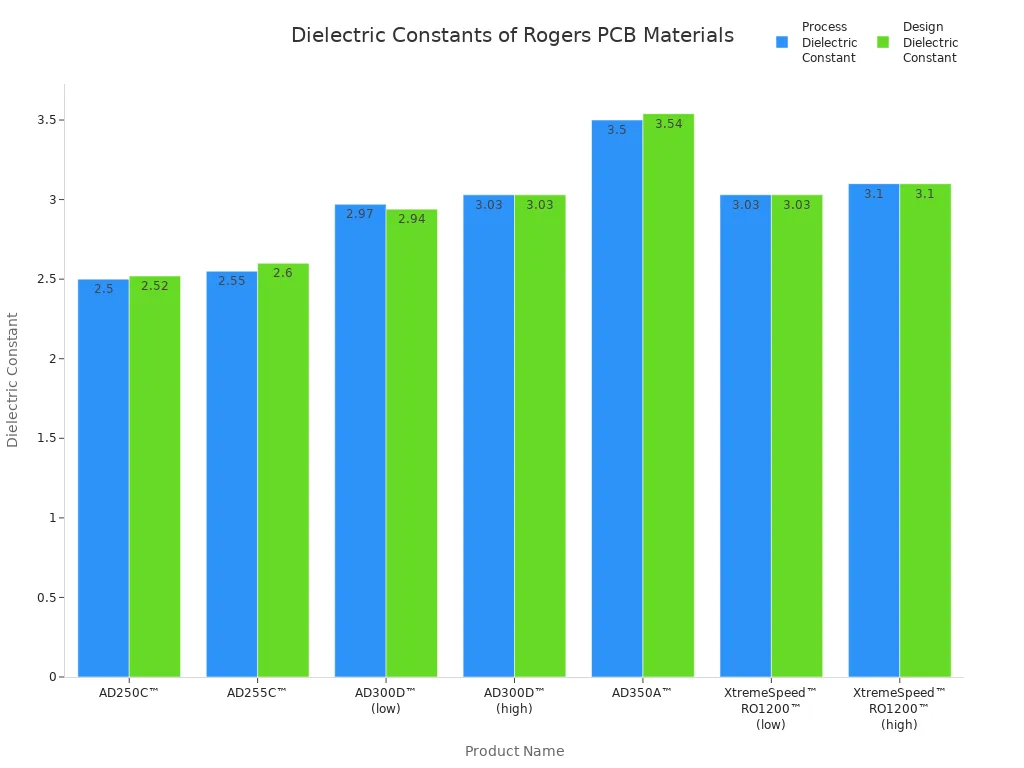
Product Name | Dielectric Constant (Process) | Dielectric Constant (Design) |
|---|---|---|
AD250C™ | 2.50+/-0.04 | 2.52 |
AD255C™ | 2.55+/-0.04 | 2.60 |
AD300D™ | 2.97, 3.03 +/-0.05 | 2.94, 3.03 |
AD350A™ | 3.50+/-0.05 | 3.54 |
XtremeSpeed™ RO1200™ | 3.03-3.10+/-0.10 | 3.03-3.10 |
When designing high-performance electronics, it’s essential to consider the rogers pcb dielectric constant, as it plays a crucial role in signal integrity and overall device performance. LT CIRCUIT leverages advanced Rogers materials with precise dielectric constant values to provide superior PCB solutions tailored to your project’s requirements.
Key Takeaways
Rogers PCB materials have a dielectric constant range from 2.2 to 11, allowing you to choose the best option for high-frequency applications.
A lower dielectric constant improves signal transmission speed and integrity, making Rogers PCBs ideal for advanced electronics like 5G devices.
Selecting the right Rogers PCB material ensures stable performance, minimizes signal loss, and enhances reliability in demanding environments.
Dielectric constant basics

What is dielectric constant
You encounter the dielectric constant every time you work with PCB materials. The dielectric constant measures how much a material slows down electrical signals compared to a vacuum, which has a value of 1. All PCB laminates, including Rogers PCB materials, have dielectric constants greater than 1. You often see the terms Dk and er used interchangeably for this property. Manufacturers usually measure the dielectric constant using the parallel plate method at 1 MHz, but you can also calculate it based on signal velocity in the dielectric. The value changes with frequency and depends on the glass-to-resin ratio in the laminate. More resin lowers the dielectric constant, while less resin increases it. The dielectric constant is a complex number, and its imaginary part, called the dissipation factor, affects the loss tangent and overall performance.
Note: Rogers PCB dielectric constant values range from 2.5 to 11, while standard FR-4 materials have a dielectric constant around 4.5. This wide range allows you to select the best high-frequency laminate material for your application.
Why dielectric constant matters
The dielectric constant directly impacts signal transmission speed and integrity in your PCB designs. Lower dielectric constant values allow signals to travel faster, which is critical for high-frequency and RF applications. Rogers PCB materials offer low loss and maintain signal integrity, especially at high frequencies. You need to consider the dielectric constant when calculating impedance, which affects trace width and spacing. Choosing a low dielectric constant material helps reduce crosstalk and improves overall performance. Rogers PCB boards provide stable impedance and minimize signal loss, making them ideal for advanced electronics.
LT CIRCUIT uses only high-quality Rogers PCB materials to ensure your designs achieve optimal performance and reliability.
Rogers PCB dielectric constant range
Common Rogers materials
You have many options when you choose Rogers PCB materials for your project. Rogers offers a wide selection of high-frequency laminate materials, each with unique properties. Some of the most popular Rogers PCB materials include RO3003, RO4003C, RO4350B, and RO4360. These materials stand out because they provide stable dielectric constant values and low loss, which are essential for high-frequency and RF applications.
Here is a quick overview of some common Rogers PCB materials and their key properties:
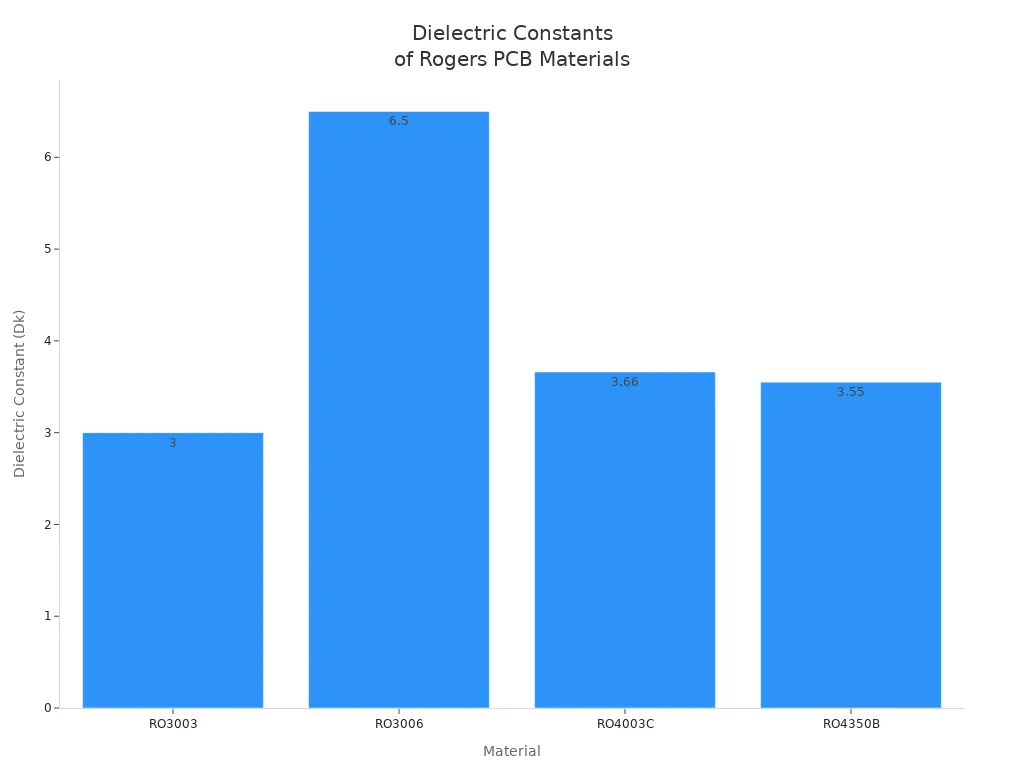
Material | Dissipation Factor (Df) | Thermal Conductivity (W/m*K) | |
|---|---|---|---|
RO3003 | 3 | 0.001 | 0.5 |
RO3006 | 6.5 | 0.002 | 0.79 |
RO4003C | 3.66 | 0.0031 | 0.71 |
RO4350B | 3.55 | 0.0021 | 0.69 |
You can see that these Rogers PCB materials cover a wide range of dielectric constant values, making them suitable for many different applications.
Dielectric constant values
The dielectric constant is a critical property that affects signal transmission speed and integrity in your PCB designs. Rogers PCB dielectric constant values range from as low as 2.2 up to 10.2, depending on the specific material you select. This broad range allows you to match the right material to your application's needs.
Material | |
|---|---|
Rogers PCB | 2.2 to 10.2 |
Rogers PCB | 2.55 to 10 |
When you compare Rogers PCB dielectric constant values to standard materials like FR4, you notice a significant difference. FR4 usually has a dielectric constant around 4.5, while Rogers materials offer both lower and higher options. This flexibility helps you optimize signal transmission and performance for high-frequency designs.
Rogers PCB materials with low dielectric constant values, such as RO3003 and RO4003C, support faster signal transmission and reduce signal loss. These materials also maintain stable performance across a wide frequency range. You benefit from low loss and consistent electrical properties, even as temperatures change or frequencies increase.
Tip: When you design a 5G antenna or other high-frequency device, choosing a Rogers PCB with a dielectric constant around 3.0 can help you maintain signal integrity and minimize delays.
LT CIRCUIT and Rogers PCB solutions
LT CIRCUIT specializes in helping you select the best Rogers PCB dielectric constant for your specific application. The team at LT CIRCUIT understands how different dielectric constant values impact performance, signal transmission, and reliability. You can rely on their expertise to match your requirements with the right Rogers PCB materials, whether you need low loss for RF circuits or stable impedance for high-speed digital designs.
You also benefit from LT CIRCUIT's commitment to quality. The company uses advanced manufacturing techniques to ensure consistency in dielectric constant values across every batch of Rogers PCB materials. This attention to detail means your designs will perform as expected, with reliable signal transmission and minimal variation.
When you work with LT CIRCUIT, you gain access to a wide range of Rogers PCB solutions. The team considers environmental factors, such as moisture absorption and mechanical stress, to help you choose materials that maintain their dielectric properties in real-world conditions. You can trust LT CIRCUIT to deliver high-frequency laminate material options that support your project's performance goals.
Rogers PCB applications
Signal integrity and design
You need to understand how the rogers pcb dielectric constant influences your high-performance printed circuit board design. A lower dielectric constant allows signals to travel faster, which improves signal transmission and circuit performance. You can achieve better impedance control, which helps minimize signal reflections and supports efficient power transfer. Lower dielectric values also reduce crosstalk and electromagnetic interference, making your signal integrity analysis more reliable. Rogers pcb materials with low loss tangent values preserve signal strength over long distances and minimize energy loss. High thermal conductivity in these materials helps dissipate heat, which increases board reliability under demanding conditions.
Tip: Consistent dielectric constant values across frequencies and temperatures ensure stable performance in high-frequency circuits. This stability is crucial for applications that require precise phase control and minimal signal loss.
Application suitability
You can use rogers pcb boards in many advanced electronic systems. Their stable dielectric properties make them ideal for environments that demand reliability and high-frequency operation. Common applications include:
Cellular base station antennas
Servers
Routers
Power amplifiers
Radar and sensors
Microwave equipment
High-speed backplanes
RFID tags
5G stations
Automated test equipment
Backhaul radios
Low-noise block downconverters for satellites
LT CIRCUIT offers advanced customization options for these industries. You can select materials with the right dielectric constant for your needs, ensuring optimal performance and long-term reliability. Rogers pcb boards resist moisture absorption, which helps maintain electrical properties in humid conditions and reduces the risk of delamination or failure.
Challenge Type | Description |
|---|---|
Specialized Tooling | You need adjusted drilling parameters and specialized drill bits to avoid defects. |
Lamination Control | Precise temperature and pressure control ensures optimal bonding and preserves material properties. |
Impedance Control | Maintaining signal integrity requires careful impedance matching to prevent data errors. |
You see how the rogers pcb dielectric constant affects signal integrity and overall performance. LT CIRCUIT supports your designs with advanced Rogers PCB materials and strict quality standards:
Quality Focus | Description |
|---|---|
Standards | |
Customization | Flexible stackups and thickness options |
Advanced Materials | Rogers laminates for high-frequency applications |
When you select materials, keep these tips in mind:
Match material to your operating frequency.
Choose thickness and panel size for your needs.
FAQ
What is the main advantage of using Rogers PCB materials?
You get stable electrical performance at high frequencies. Rogers PCB materials help you achieve better signal integrity and lower loss in advanced electronic designs.
How does dielectric constant affect PCB design?
You select materials with the right dielectric constant to control signal speed and impedance. This choice helps you reduce signal loss and improve circuit reliability.
Can you use Rogers PCB boards for RF applications?
You can use Rogers PCB boards for RF applications. Their consistent dielectric properties support high-frequency signals and help you maintain strong performance in demanding environments.
See Also
Exploring Rogers R4350B, R4003, And R5880 For RFPCB Use
Integrating Rogers Materials With TG170 In Hybrid PCB Designs
A Deep Dive Into Rigid-Flex PCB Structures And Designs