What Makes Rogers PCB Essential for High-Frequency Circuits
Rogers PCB fabrication delivers unmatched signal integrity and reliability for high-frequency designs. When you choose materials with a low dielectric constant and loss tangent, you experience superior performance.
The dielectric constant (Dk) and loss tangent (Df) of PCB materials are essential for maintaining signal integrity, especially in advanced applications.
LT CIRCUIT is a leader in advanced Rogers PCB fabrication, ensuring top-quality results for demanding projects.
Material | Frequency Range | |
|---|---|---|
FR-4 | Higher | Standard |
Rogers RO4350B | Lower | High-frequency |
Key Takeaways
Rogers PCB offers superior signal integrity and low signal loss, making it ideal for high-frequency applications like RF and 5G systems.
The unique properties of Rogers materials, such as low dielectric constant and high thermal stability, ensure reliable performance in demanding environments.
Choosing Rogers PCB can significantly enhance data transmission speeds and reduce latency, crucial for modern communication networks.
Rogers PCB and Rogers Material
What Is Rogers PCB?
You will notice that rogers pcb stands out in high-frequency circuit design. Rogers pcb uses rogers material, which offers superior dielectric properties and high dimensional stability. You can rely on rogers pcb for applications that demand low water absorption and good chemical resistance. Rogers pcb features controlled and low dielectric constants, low signal loss, excellent thermal conductivity, and high reliability. These qualities make rogers pcb ideal for RF, microwave, and 5G systems. LT CIRCUIT uses advanced rogers material, such as RO4350B and the Rogers 4000 series, to deliver consistent performance for your high-frequency needs.
Rogers pcb provides you with minimal dielectric loss and high impedance control, ensuring your signals remain clear and strong.
Rogers Material Properties
Rogers material offers unique properties that set it apart from standard PCB laminates. You can see the difference in the table below:
Property | RO4350B | RO4003C |
|---|---|---|
Dielectric Constant | 3.38 +/- 0.05 | |
Dissipation Factor | 0.0037 @ 10GHz | 0.0027 @ 10GHz |
Available Thickness | 0.008 to 0.062 in | Not specified |
Surface Roughness | 0.5 to 1.5 µm | Not specified |
Z-axis CTE | 32 ppm/°C | 46 ppm/°C |
Flame Retardant Grade | UL 94 V-0 | Not specified |
You benefit from superior dielectric properties, low water absorption, and high dimensional stability with rogers material. Rogers pcb also provides excellent thermal conductivity and dimensional stability, which helps maintain performance in demanding environments.
Comparison with Standard PCBs
When you compare rogers pcb to standard FR-4 boards, you see clear advantages. Rogers material delivers a lower dielectric constant and loss tangent, which means less signal loss and better performance at high-frequency. The table below shows the difference:
Material | Loss Tangent (Dissipation Factor) | |
|---|---|---|
Rogers | 6.15 to 11 | ~0.004% |
FR-4 | ~4.5 | ~0.02% |
Rogers pcb also offers better thermal stability and thermal conductivity. You get reliable operation and dimensional stability, even in high-power or temperature-sensitive applications. LT CIRCUIT uses rogers material to ensure your high-frequency designs perform at their best.
High-Frequency PCBs: Performance and Benefits
Signal Integrity and Low Loss
You need reliable signal integrity when you design high-speed applications. Rogers pcb gives you a stable dielectric constant and a low loss tangent, which prevent signal distortion. This means your data moves accurately, even at speeds over 10 Gbps. Rogers pcb also reduces crosstalk, so signals on adjacent traces do not interfere with each other. You get low signal loss, which is essential for microwave and RF circuits.
Here is a table that shows the key performance metrics for rogers pcb in high-frequency applications:
Metric | Description |
|---|---|
Superior Signal Integrity | Stable dielectric constant and low loss tangent prevent signal distortion, ensuring accurate data transmission at speeds exceeding 10 Gbps. |
Reduced Crosstalk | Consistent electrical properties across the board minimize interference between adjacent traces. |
Low Loss Tangent | Values as low as 0.0009 in some products minimize signal loss, ideal for microwave PCB applications. |
You can see that rogers pcb supports high-speed applications by minimizing insertion loss and maintaining clear signals. This makes it the best choice for high-frequency pcbs in high-performance electronics.
Tip: For high-frequency performance, always select a high-performance substrate like rogers pcb to ensure low noise and minimal signal degradation.
Thermal and Mechanical Stability
Rogers pcb stands out for its excellent thermal and mechanical stability. You want your high-frequency pcbs to perform well, even when exposed to heat or mechanical stress. Rogers pcb materials have a low thermal expansion coefficient, which means they expand very little when heated. This property keeps your circuits stable and reliable.
The thermal expansion coefficient measures how much a material expands when heated, usually in parts per million (ppm).
Rogers pcb maintains tight tolerances during both processing and operation, so you get consistent results.
Increased thermal conductivity helps distribute heat across the board, reducing hotspots and supporting good thermal management.
You benefit from exceptional thermal stability and dimensional accuracy. Rogers pcb resists degradation from humidity, chemicals, and mechanical stress. This reliability is critical for aerospace and defense, where harsh environments are common.
Here are some documented reliability improvements you gain with rogers pcb:
Reliability Improvement | Description |
|---|---|
Superior Performance at High Frequencies | Maintains electrical properties well into the millimeter-wave range. |
Exceptional Thermal Stability | High thermal conductivity (between 0.5 and 2 W/mK) provides reliable performance across extreme temperature ranges. |
Low Signal Loss | Minimizes insertion loss for maximum signal integrity and power efficiency. |
Dimensional Stability | Maintains tight tolerances during processing and operation. |
Uniform Material Structure | Provides consistent performance across the board. |
Reliability in Harsh Environments | Resists degradation from humidity, chemicals, and mechanical stress. |
Consistent Electrical Properties | Ensures predictable performance in critical applications. |
Enhanced Longevity | Extends product lifespan in demanding applications. |
You can trust rogers pcb for high-speed applications that require good thermal management and mechanical strength.
Real-World Applications
You will find extensive applications for rogers pcbs in industries that demand high-frequency performance. Telecom, RF, microwave, and 5G systems all rely on rogers pcb for their high-speed applications. Rogers pcb helps you achieve lower latency and faster data transmission, which is vital for modern communication networks.
Here are some real-world examples:
Application | Performance Outcome |
|---|---|
A leading telecommunications company used Rogers FR-4 PCBs in their 5G base station equipment. | Marked improvement in data transmission speeds and reduced latency, enabling faster and more reliable connectivity for users. |
A major telecommunications company utilized Rogers 4350B PCBs in the design of a 5G base station. | Superior thermal management and signal integrity significantly improved performance, enabling faster data transmission and reduced latency. |
You also see rogers pcb used in aerospace and defense, where reliability and performance are critical. High-frequency pcbs made with rogers material support radar, satellite, and navigation systems. These applications require low noise, low signal loss, and consistent performance in harsh environments.
LT CIRCUIT delivers high-frequency pcbs for high-speed applications in telecom, aerospace and defense, and advanced RF systems. You can rely on their expertise to meet your most demanding requirements.
Rogers PCB Fabrication and LT CIRCUIT Expertise
Manufacturing Process
You will notice that rogers pcb fabrication involves several precise steps to ensure high-frequency performance.
You start with careful material handling and preparation, since Rogers materials need controlled storage.
Inner layer processing uses precise copper foil and tight tolerances for imaging and etching.
Layer stackup and lamination require strict control to maintain electrical properties.
Drilling uses specialized bits and parameters to protect the material.
Plating and outer layer processing follow, with tighter controls than standard boards.
Solder mask and silkscreen application use special materials.
Surface finish, such as ENIG, supports RF performance.
Electrical testing and quality control include impedance and dimensional checks.
LT CIRCUIT uses advanced techniques like laser direct imaging and microvia drilling to support complex designs and design flexibility.
Quality and Customization
You benefit from strict quality standards during rogers pcb fabrication. LT CIRCUIT follows IPC-A-600, IPC-2221, and IPC-J-STD-001 standards, as shown below:
Quality Control Standard | Description |
|---|---|
IPC-A-600 | Acceptability criteria for fabrication |
IPC-2221 | Design standards for trace width and spacing |
IPC-J-STD-001 | Soldering process requirements |
You can choose from various stackup configurations, such as 4-layer, 6-layer, or higher. These options give you design flexibility and improve signal integrity. LT CIRCUIT also offers custom thickness, surface finishes, and embedded components, which support design flexibility and miniaturization.
Considerations and Challenges
You may face challenges during rogers pcb fabrication, such as interconnect defects or heat dissipation. LT CIRCUIT addresses these by using advanced microvia formation and selecting materials with low dielectric constants. Engineers focus on design flexibility to reduce electromagnetic interference and improve performance. Environmental standards matter, so LT CIRCUIT uses halogen-free materials and meets RoHS and REACH regulations. You can trust their expertise to deliver reliable, high-frequency PCBs.
You choose Rogers PCBs for high-frequency circuits because they deliver low signal loss, stable performance, and reliability.
Rogers Corporation holds a 30% market share in high-frequency circuit industries, showing strong adoption for 5G and military uses.
LT CIRCUIT Strength | Details |
|---|---|
Precision lamination, laser drilling, and in-line impedance control | |
Quality Certifications | ISO 9001, IPC-A-600 Class 3, RoHS/REACH compliance |
You see advanced materials like Rogers laminates shaping the future as electric vehicles and 5G drive demand for high-performance, eco-friendly electronics.
FAQ
What makes Rogers PCB better for high-frequency circuits?
You get stable signals and low loss with Rogers PCB. The material supports high-speed data and reduces interference in advanced electronic designs.
Tip: Rogers PCB helps you achieve reliable performance in 5G and RF systems.
Can you use Rogers PCB for multilayer designs?
Yes, you can use Rogers PCB for multilayer boards. The material supports complex stackups and maintains signal integrity across all layers.
How does LT CIRCUIT ensure Rogers PCB quality?
LT CIRCUIT uses strict testing, advanced manufacturing, and certified processes. You receive PCBs that meet high standards for reliability and performance.
See Also
Exploring Rogers R4350B, R4003, And R5880 For RFPCB Use
Designing High Frequency PCBs: Key Manufacturing Insights And Factors
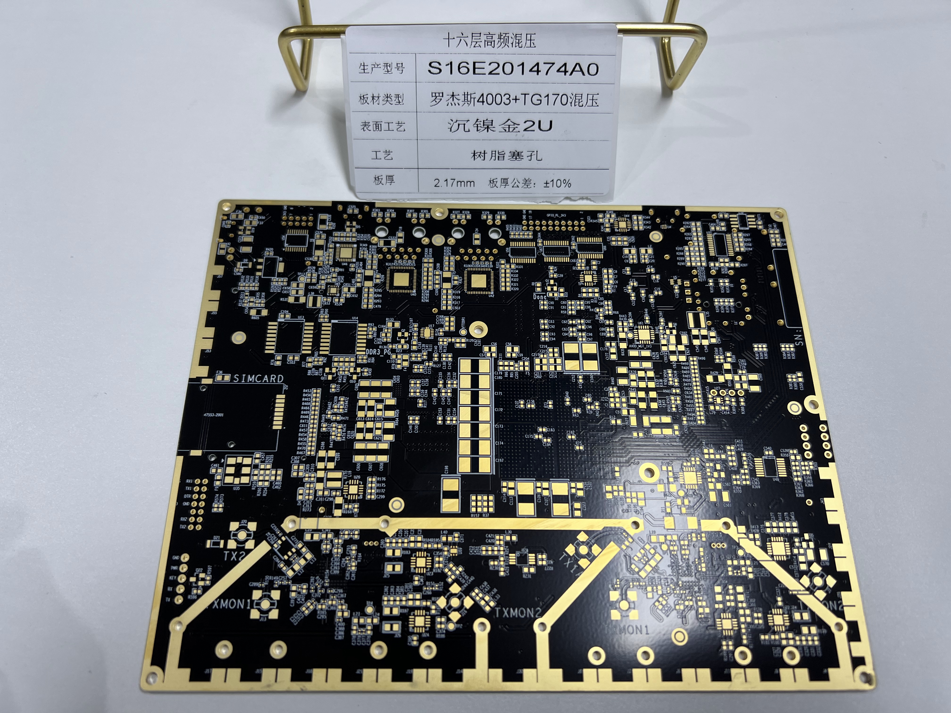
Integrating Rogers Materials With TG170 For Hybrid PCB Solutions
Top Materials Recommended For High-Speed PCB Design Projects