Why Choose Rogers PCB Prototype for Fast Results in 2025
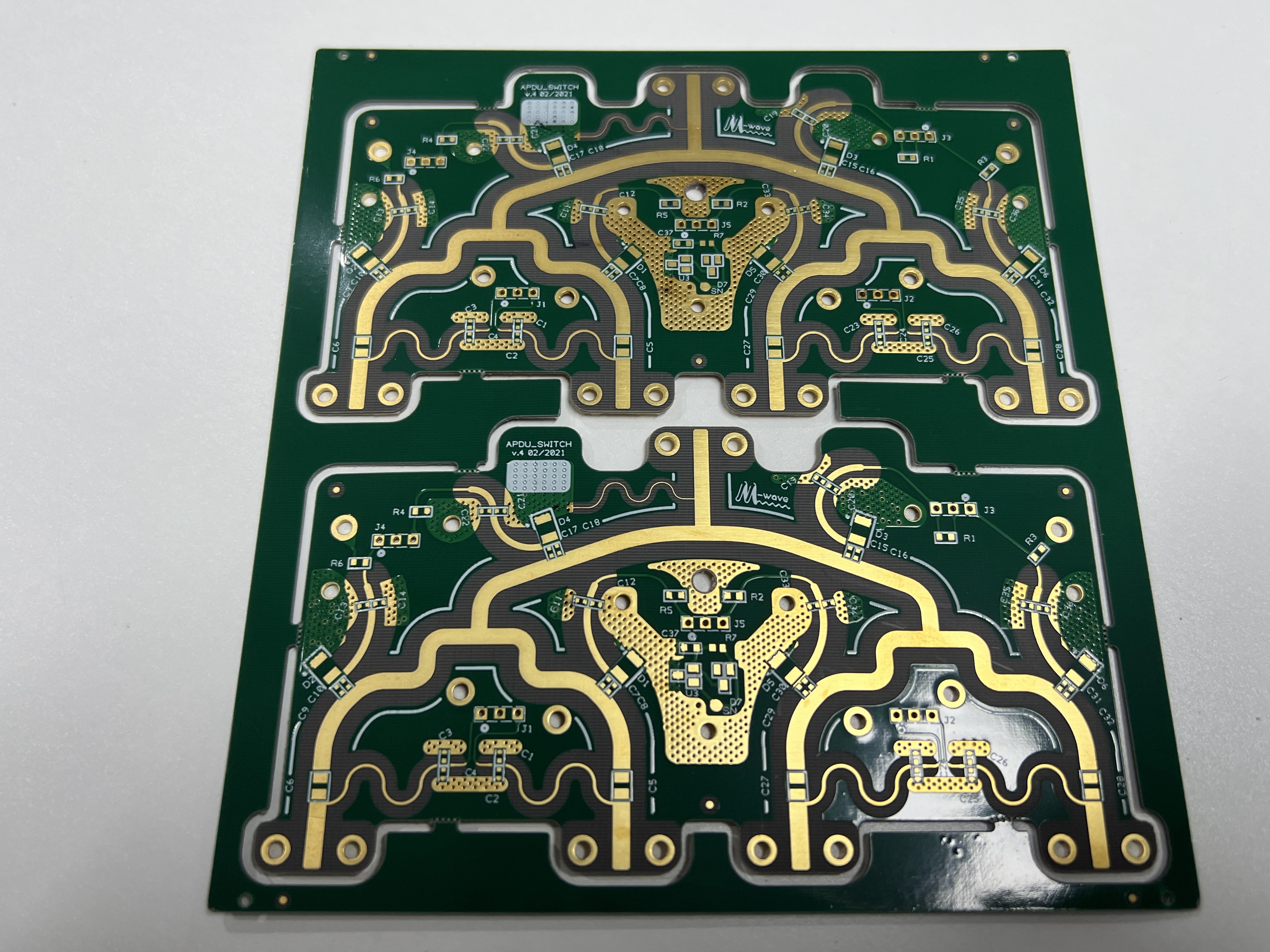
In 2025, you need fast and reliable solutions for high-frequency applications, and a Rogers PCB prototype is the ideal choice for superior speed and performance. LT CIRCUIT specializes in delivering advanced Rogers PCB prototype solutions that are trusted by engineers around the globe.
Benefit | Description |
|---|---|
Reduces signal loss and crosstalk in high-frequency Rogers PCB prototype designs. | |
Low Loss Tangent | Minimizes energy dissipation, ensuring efficient operation in every Rogers PCB prototype. |
Thermal Stability | Handles temperatures up to 280°C, making the Rogers PCB prototype suitable for harsh environments. |
Rogers PCB prototype holds a 35% market share in high-frequency PCB prototypes.
Key Takeaways
Rogers PCB prototypes offer low signal loss and high signal integrity, making them ideal for high-frequency applications.
LT CIRCUIT provides rapid prototyping services, delivering Rogers PCBs in just 24–48 hours, significantly faster than the industry average.
The advanced materials used in Rogers PCBs ensure thermal stability and durability, allowing them to perform reliably in harsh environments.
High-Frequency Performance
Signal Integrity
You need reliable signal integrity when working with high-frequency applications. Rogers PCB materials from LT CIRCUIT help you achieve this goal. These materials offer low loss characteristics, which means you experience low signal loss even at high-frequency bandwidth. Signal integrity matters most in RF, microwave, and wireless designs. You want your signals to travel without distortion or interference. Rogers PCBs provide stable dielectric properties, so your circuits maintain consistent impedance and minimize reflections.
Tip: Choosing Rogers PCB materials ensures your signals remain clear and strong, even as frequencies increase.
Let’s look at the technical properties that support signal integrity in high-frequency applications:
Property | Description |
|---|---|
Ensures predictable signal behavior, crucial for maintaining impedance in high-frequency circuits. | |
Low Loss Tangent | Minimizes signal loss, ideal for microwave PCB applications, with values as low as 0.0009. |
Thermal Stability | Maintains performance in harsh environments with thermal coefficients of dielectric constant below 50 ppm/°C. |
High Thermal Conductivity | Dissipates heat effectively in high-power designs, with values up to 1.0 W/mK. |
Mechanical Strength | Supports complex multilayer designs while maintaining durability. |
You see the difference when comparing Rogers materials to standard FR-4. Rogers materials have dissipation factors ranging from 0.0009 to 0.0037. Standard FR-4 has a typical dissipation factor of 0.02. At 10 GHz, Rogers RO4350B shows a loss tangent of 0.0037, resulting in less than 0.5 dB signal loss per inch. FR-4 can exceed 1 dB under similar conditions. This means you get low signal loss and better signal integrity with Rogers PCBs.
You face challenges like electromagnetic interference and signal degradation in high-frequency bandwidth designs. Rogers PCB materials address these issues with controlled impedance and proper grounding. You benefit from low loss characteristics and low signal loss, which help you maintain signal integrity across your entire circuit.
Stable Dielectric Properties
Stable dielectric properties play a key role in high-frequency applications. Rogers PCB materials offer predictable dielectric constants, which help you control impedance and reduce signal reflections. You want your signals to propagate quickly and efficiently. Lower dielectric constants allow signals to move faster, reducing delays and improving high-frequency performance.
Signal propagation improves with lower dielectric constants.
Impedance control becomes easier, minimizing signal reflections and ensuring efficient power transfer.
Crosstalk and electromagnetic interference decrease, thanks to low dielectric loss and low loss characteristics.
Miniaturization becomes possible, allowing you to design compact PCBs with tight trace spacing.
You need stable dielectric properties to maintain signal integrity and achieve low signal loss. Rogers PCB materials give you the confidence to design for high-frequency bandwidth without worrying about performance drops. You can rely on LT CIRCUIT to deliver Rogers PCBs that meet your requirements for low loss characteristics and signal integrity.
Rogers PCB materials are designed for high-frequency applications. You get excellent dielectric integrity and thermal stability. These features help you reduce electromagnetic interference and ensure reliable signal integrity in demanding environments. You can trust LT CIRCUIT to provide solutions that support your need for low signal loss and high-frequency bandwidth.
Fast Rogers PCB Prototype
Quick Turnaround
You want your project to move quickly from concept to reality. LT CIRCUIT delivers rapid rogers pcb prototype services that help you meet tight deadlines. The average lead time for a rogers pcb prototype at LT CIRCUIT is just 24–48 hours. Most competitors take 5–7 days. This speed gives you a clear advantage when you need to test and refine designs for high-frequency applications.
Metric | LT CIRCUIT Performance | Industry Average |
|---|---|---|
Prototype Lead Time | 24–48 hours | 5–7 days |
You benefit from LT CIRCUIT’s efficient manufacturing process. The team uses advanced techniques like laser drilling and automated optical inspection. These methods reduce errors and speed up production. Rogers materials are always available, so you do not wait for supplies. You get your rogers pcb prototype fast, which keeps your project on schedule.
Tip: Fast turnaround lets you test, iterate, and launch products for high-frequency applications without delays.
Design Flexibility
You need flexibility when designing circuits for high-frequency applications. Rogers PCB materials offer features that support creative layouts and complex requirements. You can choose up to 16 layers for your rogers pcb prototype. The materials resist warping and maintain stable performance, even at high temperatures.
Design Feature | Description |
|---|---|
Low dielectric constant (Dk) | Maintains signal integrity and minimizes signal loss at high frequencies and over long distances. |
Low loss tangent (Df) | Minimizes signal attenuation and distortion. |
High thermal conductivity | Effectively dissipates heat and maintains stable performance even at high temperatures. |
Dimensional stability | Less likely to warp or deform under temperature changes due to low coefficient of thermal expansion. |
Uniform material structure | Provides consistent performance across the board. |
You can create compact, reliable, and high-performance rogers pcb prototype layouts. LT CIRCUIT supports your design goals with advanced manufacturing and material options. You get the flexibility to innovate and solve challenges in high-frequency applications.
Reliability in High-Frequency Applications
Thermal Stability
You need thermal stability when you design for high-frequency applications. Rogers PCB materials from LT CIRCUIT give you this advantage. These materials use advanced hydrocarbon ceramic and PTFE composites. You get thermal stability because these materials keep their shape and performance even when temperatures rise. Thermal stability means your circuits do not warp or delaminate during continuous operation. You can trust your design to work in high-power situations. Rogers PCB materials also offer high-temperature resistance. You see thermal stability in every layer, which helps you manage heat and keep your signals clear. When you use LT CIRCUIT, you get thermal stability that supports your project from start to finish. Thermal stability is important for high-frequency applications because it keeps your board reliable. You do not worry about sudden temperature changes. Rogers PCB materials maintain thermal stability, so your circuits stay strong. You get high-temperature resistance, which means your board works in harsh environments. Thermal stability protects your investment and helps you deliver quality results.
Note: Thermal stability ensures your PCB prototype performs well in high-frequency applications, even under extreme heat.
Long-Term Durability
You want your PCB to last. LT CIRCUIT meets strict environmental reliability standards. Rogers PCB prototypes go through tough tests to prove their long-term durability. You see the results in the table below:
Standard | Description |
|---|---|
Ensures rigorous inspection with no defects affecting signal integrity. | |
Thermal Cycling | Tests from -40°C to 125°C to validate reliability in extreme conditions. |
Vibration Testing | Conducted at 20G to ensure durability for aerospace and automotive clients. |
You get long-term durability because Rogers PCB materials resist wear and tear. Thermal stability helps your board survive many cycles of heating and cooling. High-temperature resistance keeps your PCB safe in demanding environments. You can rely on LT CIRCUIT for high-frequency applications that need both thermal stability and durability. Your project stays reliable year after year.
Cost-Effective Rogers PCB Solutions
Reduced Rework
You want to avoid costly mistakes and repeated testing in your high-frequency PCB projects. Rogers PCB materials from LT CIRCUIT help you achieve this goal. These materials offer stable dielectric properties and low loss characteristics, which means your designs work as expected the first time. You spend less time troubleshooting and more time moving forward. LT CIRCUIT uses AI-driven quality control to keep defect rates below 1%. This high level of precision means you rarely need to redo a prototype. You get reliable results, even in demanding applications like medical devices and 5G modules.
Tip: Fewer defects and less rework save you valuable time and resources during development.
Lower Project Costs
You want to keep your project budget under control. LT CIRCUIT’s advanced manufacturing process helps you do that. The Rogers 4000 series offers a cost-effective solution for high-frequency designs. You benefit from optimized layouts and efficient production methods. LT CIRCUIT’s expertise in any-layer HDI technology shortens signal paths by 30% in 5G modules. This improvement lowers latency and boosts performance without increasing costs. Customization and support from LT CIRCUIT reduce your expenses by 15–20% while maintaining high quality.
Here’s how LT CIRCUIT’s strategies help you save:
Strategy | Benefit |
|---|---|
Any-Layer HDI Expertise | Shortens signal paths, improves performance, and reduces material usage. |
AI-Driven Quality Control | Keeps defect rates low, minimizing costly rework and delays. |
Customization & Support | Optimizes designs for your needs, lowering costs without sacrificing reliability. |
You get a cost-effective Rogers PCB solution that supports your high-frequency project goals. LT CIRCUIT helps you deliver quality results while keeping your budget in check.
LT CIRCUIT Success Stories
2025 Case Study
You want to see real results before choosing a Rogers PCB prototype. In early 2025, a telecom company needed a fast solution for a new 5G module. The engineers faced strict deadlines and high-frequency design challenges. You would have seen how LT CIRCUIT stepped in with rapid prototyping using Rogers 4000 series materials. The team delivered the first batch of prototypes in just 36 hours. The company tested the boards and found stable signal integrity and low loss at 10 GHz. The project moved from concept to field testing in less than a week. You can achieve similar speed and reliability for your own high-frequency projects.
Note: Fast prototyping and stable performance help you launch products ahead of competitors.
Industry Feedback
You want to know what other clients say about LT CIRCUIT. Many electronics makers in telecom, aerospace, and medical fields trust LT CIRCUIT for Rogers PCB prototypes. Clients praise the reliability and high quality of the products. You benefit from strong HDI skills and advanced technology that meet your needs. Excellent customer support guides you through every step. Large orders move quickly, and prices stay fair.
Feedback Aspect | Client Comments |
|---|---|
Reliability | LT CIRCUIT maintains high quality and reliability in every product. |
Performance | Clients value strong HDI skills and advanced technology. |
Customer Support | You receive excellent support throughout the process. |
Order Handling | Large orders are handled quickly with fair pricing. |
Industry Recognition | Trusted by telecom, aerospace, and medical electronics makers. |
You can rely on LT CIRCUIT for your next high-frequency project. The company’s reputation and client feedback show you get results you can trust.
You gain speed, reliability, and high performance with Rogers PCB prototypes from LT CIRCUIT. See how they compare:
Metric | FR-4 HDI | Ceramic PCBs | PTFE Non-HDI PCBs | |
|---|---|---|---|---|
Signal Loss at 60GHz | 0.3 dB/inch | 1.8 dB/inch | 0.2 dB/inch | 0.25 dB/inch |
Design Flexibility | High | Medium | Low | Low |
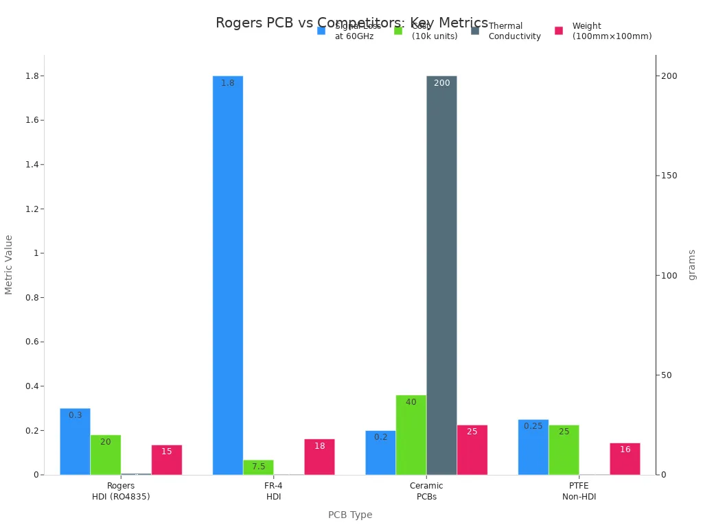
Choose LT CIRCUIT for your next project. You stay ahead as flexible, low-loss PCBs drive innovation in 2025’s high-frequency world.
FAQ
What makes rogers pcb better for high-frequency designs?
You get stable signal integrity and low loss with rogers pcb. The material supports high-frequency designs and keeps your circuits reliable.
How fast can you receive a rogers pcb prototype from LT CIRCUIT?
You receive your rogers pcb prototype in 24–48 hours. LT CIRCUIT uses efficient manufacturing to deliver your order quickly.
Can you customize the layer count and finish for your rogers pcb?
You choose up to 16 layers and select finishes like ENIG or HASL for your rogers pcb. LT CIRCUIT supports your design needs.
Tip: You improve your project’s performance by choosing the right rogers pcb options.
See Also
Selecting A Reliable PCB Manufacturer For Your Company Needs
Saving Project Costs With Quick Turn HDI PCBs In 2025
Key Steps For Efficient Fast Turnkey PCB Assembly
Exploring Rogers R4350B, R4003, And R5880 For RFPCB Use
Top Materials Recommended For High-Speed PCB Design Projects