Top Technical Challenges and Solutions in HDI PCB Fabrication
HDI PCB fabrication involves several technical challenges that can impact the performance of the boards. Issues such as interconnect defects caused by dirt or copper bond failure can lead to layer separation. Mechanical problems like board bending, misaligned layers, and micro-cracks are also common. Additionally, electromagnetic interference and heat dissipation problems often arise in densely packed designs.
HDI PCBs play a crucial role in modern electronics, being widely used in smartphones, automotive systems, and advanced communication devices. The demand for HDI PCBs has surged due to the growing need for smaller, more efficient products. LT CIRCUIT stands out by prioritizing quality and innovation in hdi pcb fabrication, ensuring reliable and cutting-edge solutions for the electronics industry.
Key Takeaways
HDI PCBs have problems like small microvia defects, crowded routing, signal interference, and heat buildup. These issues can hurt how the board works and how long it lasts.
Using new methods like laser drilling, controlled impedance routing, thermal vias, and picking the right materials helps fix these problems. These steps make the board better.
Planning early, doing careful quality checks like flying probe testing, and following design rules help HDI PCBs work well in new electronics and last longer.
HDI PCBs Overview
What Is High-Density Interconnect?
High-density interconnect means a type of printed circuit board that uses special technology to fit more wires in a small space. HDI PCBs use microvias, blind vias, buried vias, and are made with sequential lamination. These things help engineers make devices that are smaller, lighter, and more complicated. HDI flex pcb types mix the bendy features of flex circuits with the tight wiring of HDI. This makes them good for small and moving devices.
Characteristic | HDI PCBs | |
|---|---|---|
Microvias, blind vias, buried vias, staggered and stacked microvias | Through-hole vias only | |
Line Width and Spacing | Finer lines and spaces (e.g., 2/2 mil) | Thicker traces and wider spacing (e.g., 3/3 mil) |
Layering Method | Sequential lamination with multiple HDI layers | Single lamination, fewer layers |
Manufacturing Process | Advanced techniques including laser drilling, electroless plating | Mechanical drilling, simpler plating |
Board Thickness | Thin, can be below 0.8mm even with 10 layers | Thicker with increased layers |
Performance | Higher wiring density, improved signal integrity, lower power consumption | Lower density, less optimized for high-speed signals |
Application Suitability | Compact, high-performance devices like smartphones and portable electronics | Larger, less dense applications |
HDI PCBs must follow rules like IPC/JPCA-2315 and IPC-2226. These rules help make sure every HDI and HDI flex pcb works well and is good quality.
Applications and Benefits
HDI PCBs are used in many fields. People use them in electronics, medical tools, cars, airplanes, and phones. These boards help make things smaller, fit more wires, and last longer.
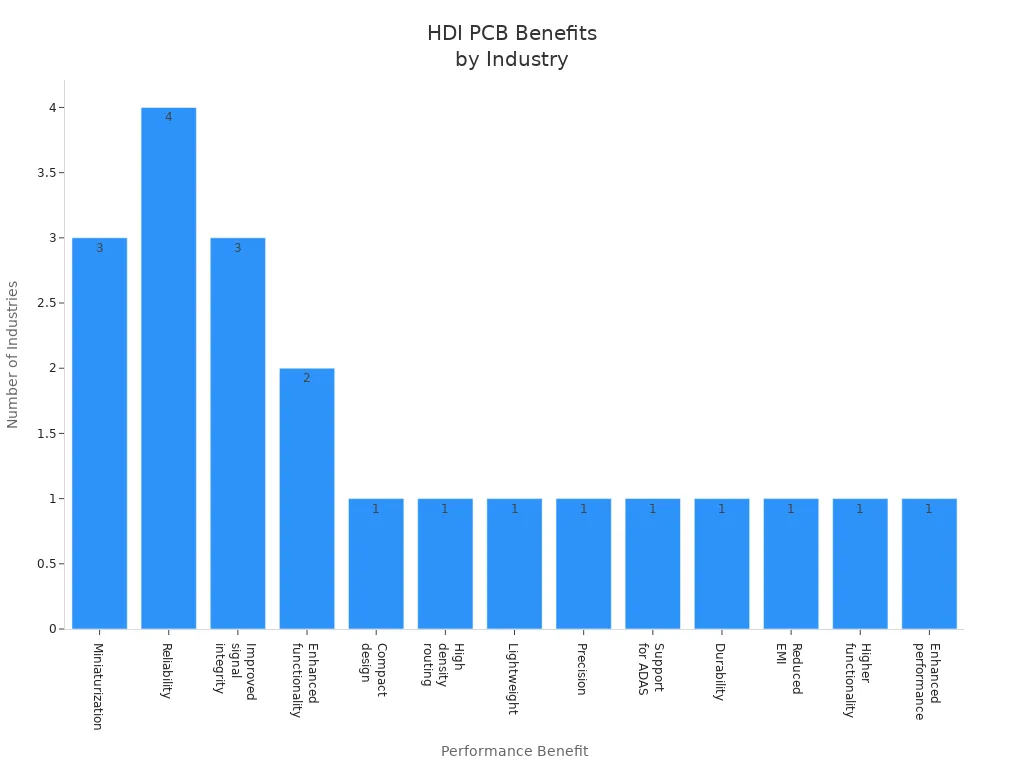
HDI PCBs give better signal quality, less electromagnetic interference, and longer life for products. HDI flex pcb designs are light and bendy, so they work well in wearable gadgets and new electronics. Engineers pick HDI PCBs and HDI flex pcb types to build modern and powerful products.
Microvia Formation
Drilling and Plating Issues
Microvia formation is very important in hdi pcb fabrication. Engineers have many problems when making these tiny connections. Mechanical drilling cannot make holes smaller than 6 mils. So, most hdi designs use laser drilling instead. Laser drilling is very accurate, but it must be controlled carefully. If the laser misses or goes too deep, it can leave dirt or make uneven holes. These mistakes can cause plating problems like empty spots, bumps, or dents. These problems make the board weaker.
Plating also has its own problems. Microvias need a smooth copper layer inside each hole. The copper must fill the via with no empty spaces. If the copper does not fill the via, it might crack during soldering or use. Engineers must also watch the aspect ratio of the microvia. A low aspect ratio, like 0.75:1, is best for strength. Higher ratios make cracks more likely, especially at the neck of the via. Microvia-in-pad designs help with soldering. But they make plating and filling harder.
Other common problems are:
Drill walk happens when the drill bit moves off-center and makes holes in the wrong place.
Dirt from drilling can block vias and cause failures.
Stress in the copper plating can make it crack from heat or shaking.
Layers can get misaligned during lamination, causing electrical problems.
Manufacturers need very accurate machines and strict controls to fix these problems. They must pick the right entry and backup materials to stop drill walk and dirt. Careful testing, like heating and bending tests, helps find early problems and improve success rates.
Tip: Automated optical inspection (AOI) and X-ray systems help engineers find microvia problems before the board leaves the factory.
Advanced Techniques by LT CIRCUIT
LT CIRCUIT uses advanced microvia formation methods for strong hdi pcb fabrication. The team uses the newest tools, like UV and CO2 laser drilling systems. These lasers make clean and even microvias with little dirt. Engineers set the drilling to make sure each hole is the right size and depth.
For plating, LT CIRCUIT uses both electroless and electrolytic copper processes. This makes sure the copper fills the via with no empty spots and sticks well to the walls. Plasma etching cleans the via sides, so they are ready for copper. The company also uses special entry and backup materials, like soft-coated Bullseye and melamine-coated Slickback, to stop drill walk and make better vias.
LT CIRCUIT’s process includes:
Real-time checks to keep layers lined up.
Special plating settings to get even copper fill.
Automated checks to make sure microvias are good.
Design for manufacturing (DFM) rules to avoid features that lower success.
The engineering team keeps learning new hdi pcb fabrication skills. They follow IPC standards so every board meets industry rules. By using new microvia methods and strict quality checks, LT CIRCUIT gives hdi solutions that work for today’s electronics.
Note: LT CIRCUIT’s focus on new ideas and quality makes it a top company in hdi pcb making and microvia strength.
Routing and Congestion
High-Density PCB Design Challenges
High-density pcb design has many problems for engineers. When more parts go into a small space, routing gets crowded. There is not much room for traces, so they can overlap or touch each other.
Space is tight, so traces are close together. This can cause crosstalk and mess up signals.
If parts are not placed right, signals can get mixed up. This can also cause electromagnetic interference and lower signal quality.
Crowded boards can get hot in some spots. This makes it hard to keep things cool and can hurt signals.
Mistakes in making the board, like layers not lining up or holes drilled wrong, can break signal paths and make building harder.
Bad routing can cause signals to bounce, mix, or arrive at the wrong time.
All these problems can make the hdi pcb work badly or break. Engineers use careful planning and new ways to fix these issues in high-density pcb design.
Trace Optimization Solutions
Engineers have ways to help with routing in crowded boards. They do not use sharp 90° turns in traces. Instead, they use smooth curves or 45° angles to stop signals from bouncing. Keeping trace widths and spaces the same helps signals stay strong.
Microvias are used instead of regular vias. This lets more traces fit and can use fewer layers in hdi pcb designs.
Special routing tools, like fanout and differential pair routing, help make better paths and stop crowding.
Putting parts in good spots and grouping them helps stop overcrowding and makes routing easier.
Engineers make sure high-speed traces are the same length. This stops timing problems.
Ground planes near important signals help control impedance and stop interference.
By using these ideas, LT CIRCUIT makes sure every high-density pcb design works well and meets the needs of new electronics.
Signal Integrity
Impedance and EMI Issues
Signal integrity is very important in HDI PCB fabrication. Engineers often have problems like impedance mismatches, electromagnetic interference (EMI), and crosstalk. These problems can cause data mistakes, lost signals, or even make the system stop working.
The main signal integrity problems in HDI designs are:
Impedance mismatches can make signals bounce back and cause errors.
Crosstalk happens when traces are too close and signals get mixed up.
EMI can happen if the stack-up is not designed well or grounding is bad.
Ground bouncing and power noise are big problems in fast circuits.
Heat can change how signals move and cause more problems.
Controlled impedance routing helps stop mismatches and bouncing signals. Engineers must watch trace width, spacing, and how far apart layers are. Microvias close to signal pads help cut down on via stubs and keep impedance steady. Solid ground planes, via stitching, and shielding help control EMI and ground bounce. Good thermal management, like using thermal vias, keeps heat from hurting signal quality.
Challenge Type | Specific Challenges | Effective Solutions |
|---|---|---|
Impedance | Keeping impedance steady with small parts and microvias; controlling trace width, spacing, and layer distance; picking materials with low dielectric constant (Dk) | Use materials like Megtron 6 with low Dk; control trace width, spacing, and layer distance; keep impedance steady from start to end |
EMI | Bad stack-up design; not enough decoupling; high PDN impedance; common mode noise | Put power and ground planes close together; use more or thicker layers; keep differential pairs close |
Tip: Simulation tools help engineers find and fix signal integrity problems before making the board.
Design and Material Solutions
Engineers use many ways to fix signal integrity problems in HDI PCBs. They start with a good layer stack-up, putting power and ground planes next to each other to lower EMI and keep signals strong. Low-loss dielectric materials, like Megtron 6, help keep impedance steady and stop signal loss.
Designers use controlled impedance routing by keeping trace widths and spacing the same. Differential pair routing helps high-speed signals and cuts down noise. Microvias, blind vias, and buried vias help keep signals steady and stop impedance changes. Putting microvias near signal pads helps too.
To stop noise and crosstalk, engineers make traces farther apart and use ground planes to keep signals apart. They route differential pairs together to keep signals clean. Solid ground planes and decoupling capacitors near power pins help keep power steady.
Thermal management is important in tight HDI designs. Engineers use thermal vias, heat sinks, and materials that move heat well to keep things cool and protect signals. Shielding boxes and filtering capacitors at key spots help lower EMI even more.
Industry standards say to do these things:
Use power and ground planes next to each other for better EMI control.
Keep impedance steady for all fast signals.
Use microvias and via-in-pad to stop signal loss.
Make traces farther apart and use ground planes to stop crosstalk.
Put decoupling capacitors close to power pins.
Use thermal vias and heat sinks to manage heat.
Add shielding and filtering where needed.
Use simulation and testing tools to check signal integrity before making the board.
LT CIRCUIT always uses these best steps in every HDI project. The team picks advanced materials and uses careful manufacturing to make sure each board meets strict signal rules. By using smart design, good materials, and strong testing, LT CIRCUIT makes HDI PCBs that work well for today’s electronics.
Thermal Management
Heat Dissipation in HDI
Thermal management is very important in HDI PCB fabrication. When many parts are close together, they make more heat. This is a big problem with processors or power devices in small spaces. Small layouts give less room for heat to leave. This makes old cooling ways not work as well. Boards with many layers can trap heat inside. Some normal PCB materials can get worse if they get too hot.
Engineers have many problems to solve:
Hotspots can show up fast and cause stress from heat.
Too much heat makes parts wear out sooner and weakens solder.
When it gets hot and cold, things can crack or come apart.
Heat makes resistance go up, so signals get weaker and work less well.
If things get too hot, it can even be unsafe.
To fix these problems, engineers put parts in smart places to spread out the heat. They use computer tools to guess where heat will go and find problems before making the board. Thermal vias, copper planes, and heat spreaders help move heat away from important spots. This makes the device work better and last longer.
Tip: Putting thermal vias right under strong parts and in a grid can make the area cooler by up to 20°C.
Material and Via Strategies
Picking the best materials and via plans helps heat move better in HDI PCBs. The table below gives some main tips:
Aspect | Recommendation |
|---|---|
Thermal Via Size | Use 0.3–0.5 mm holes to move heat well |
Via Spacing | Put vias 1–1.5 mm apart under strong parts |
Via Fill Material | Pick a fill that carries heat, like special epoxy |
Copper Thickness | Use thicker copper (like 2oz) to spread heat |
Substrate Material | Choose bases that carry heat well, like metal-core or ceramic |
Use many layers with copper planes to control heat |
Engineers also use thermal pads, heat sinks, and new materials to help heat leave faster. Working with skilled makers helps pick the best mix of materials and layout for each job.
Material Selection
Dielectric and Copper Choices
Engineers know that picking good materials is important for every hdi flex pcb. Choosing starts with the dielectric. A low dielectric constant (Dk) helps signals move faster and lose less energy. For high-frequency circuits, engineers often pick PTFE or LCP instead of FR-4. These materials help signals stay clear and lower crosstalk in hdi flex pcb designs.
Copper is just as important. Smooth, conductive copper foil keeps resistance low and helps signals move well. Thin copper is good for small traces in hdi flex pcb, but it still needs to carry enough current. The copper and dielectric must have matching CTE. This stops the board from bending or breaking when it gets hot or cold.
Engineers want these things in materials for flexible printed circuit boards and hdi flex pcb: Low Dk and low dissipation factor (Df) to stop signal loss. High glass transition temperature (Tg) for better heat resistance. Good moisture resistance to stop bending. Smooth copper for small traces and strong connections. Matching CTE between layers for long-lasting boards.
Using good materials for hdi flex pcb helps stop failures and keeps devices working longer.
LT CIRCUIT’s Material Solutions
LT CIRCUIT uses advanced materials for every hdi flex pcb and flexible printed circuit boards project. The team picks dielectrics with low Dk and high Tg for fast signals and tough places. For copper, LT CIRCUIT uses electrodeposited foil with special coatings. This keeps the copper smooth and stops rust, which is important for flex and hdi flex pcb.
LT CIRCUIT matches the CTE of all layers to stop cracks and layer splits. The company uses hydrocarbon-based materials for a good mix of price and performance in hdi flex pcb. For special jobs, like 5G or radar, the team can use PTFE or LCP for the best signals.
LT CIRCUIT’s careful material choices mean every hdi flex pcb and flex project meets strict rules for signal quality, heat resistance, and long life. Customers trust LT CIRCUIT to give them strong, high-performance flexible printed circuit boards for any use.
Layer Registration
Stacked Microvias
Stacked microvias connect layers in HDI PCBs. They save space and let engineers make more complex boards. But stacking microvias can cause problems. Engineers usually only stack two layers to avoid cracks or pads coming off. If stacked microvias sit on top of buried mechanical vias, the board can break more easily. When the board heats up, resin can expand and pull the microvia apart. Copper and dielectric materials expand at different rates. This puts stress on the microvia and can make cracks. Staggered microvias are placed in different spots on each layer. This makes the board stronger and less likely to split. Engineers pick materials that do not expand much up and down. They use single-ply prepregs to lower stress on microvias. They also keep the aspect ratio close to 1:1. This helps stop plating problems and keeps the board from getting tired.
Tip: Staggered microvias are usually stronger than stacked microvias in multilayer HDI PCB designs.
Alignment and Process Control
Getting layers lined up right is very important for HDI PCBs. Thin cores and many lamination steps make this hard. Engineers use special imaging tools like Laser Direct Imaging (LDI) for very fine detail. LDI does not need film masks. It uses UV lasers to draw circuit patterns and keep layers lined up. Cameras look for fiducial markers and fix alignment as the board is made. Laser sensors help keep layers even more accurate during lamination. Automated Optical Inspection (AOI) and X-ray scans can find tiny mistakes in alignment. Design for Manufacturability (DFM) checks and working with makers early help stop problems. These steps make sure every layer matches up. This helps the board work better and last longer.
Testing and Inspection
Accessibility in HDI PCB Fabrication
Testing HDI PCBs is hard because they are small and complex. Old testing ways do not work well on these boards. Thin traces and hidden pads, like those under BGAs, make it tough to test by hand. Engineers have trouble when they cannot reach every node or pad. They fix this by adding tiny test points for checking signals. They also use bed-of-nails fixtures for automatic tests. Planning early helps keep important test pads out from under BGAs. Thinking about testability early in design is important. Engineers also follow rules for making things easier to test. This makes sure testing problems do not stop quality checks. Working with manufacturers early helps fix testing issues before making the boards.
Tip: Adding test points and planning ahead makes debugging and checking much easier.
Advanced Testing at LT CIRCUIT
LT CIRCUIT uses new ways to solve testing problems in HDI PCB fabrication. The company uses flying probe testing because it works well for crowded boards. Flying probe testing uses very tiny probes that can touch microvias as small as 50 microns. High-resolution cameras help guide the probes to the right places. Using more than one probe, like 8-probe setups, makes testing faster and more accurate. Flying probe testing does not need special tools, so it works for many board types and lowers the chance of damage. LT CIRCUIT also uses E-test and other checks to look at electrical performance and soldering. The quality team uses online AOI, impedance testers, and microscopes to check every step. With flying probe testing, LT CIRCUIT gets a compliance rate above 99.8% for HDI boards. This careful process makes sure every board meets strict rules and solves testing problems at every step.
Best Practices and Innovation
Design for Manufacturability
Engineers use smart steps to make sure each hdi flex pcb is high quality. They pick copper foils that are thick enough for tiny, close wires. They follow strict rules for lines and spaces to stop shorts and signal trouble. Microvias with a 0.75:1 aspect ratio or less help make strong plating and good connections. Teams keep traces short and use the same impedance paths. They split up digital, analog, and power signals. Ground planes help keep signals clean.
EMI modeling uses ground planes, shielding, and decoupling capacitors to stop noise.
Thermal vias, heatsinks, and materials that move heat well help cool the board.
Materials that resist water and special coatings protect against wet air.
Boards are made to handle shaking and bending so they last longer.
Design and manufacturing teams work together to find problems early. They use advanced software to make layouts better and keep signals strong. Quality checks include flying probe testing, process checks, and watching every step. Lean manufacturing and good supply chains help make boards fast and reliable.
Tip: Plan for flying probe testing early so every hdi flex pcb and flex board can be checked for quality at each step.
Emerging Technologies in HDI
New technology is changing how hdi flex pcb fabrication works. Laser drilling, microvia making, and stacking layers let engineers fit more wires in less space. Additive manufacturing and putting parts inside the board make boards smaller and more useful. Flexible and rigid-flex PCBs are used in wearables, medical tools, and portable gadgets.
Automation and AI design tools help make boards more exact and handle tricky layouts. New materials like high-frequency laminates, polyimide, and halogen-free types help signals stay strong. Green trends push for eco-friendly materials and ways to make boards. More 5G, IoT, and edge computing means people want smaller, better hdi flex pcb solutions.
Flying probe testing works with new flex designs, checking tiny holes and thin wires.
Top companies use laser drilling and automation to make better flex boards.
Good supply chain planning keeps materials ready for hdi flex pcb production.
Note: Flying probe testing is still very important for checking quality as flex and hdi flex pcb technology gets better.
Engineers have many problems to solve with hdi pcbs. They must keep signals clear, control heat, and plan tricky paths. The table below shows some ways engineers fix these problems:
Challenge | Solution Example |
|---|---|
Signal Integrity | Careful routing, shielding, advanced materials |
Thermal Management | Thermal vias, high-conductivity substrates |
Design Complexities | Advanced software, rapid prototyping, collaboration |
Manufacturing | Laser-drilled microvias, optical inspection |
Engineers keep making hdi pcbs better by working together and trying new ideas. Teams start early, follow DFM rules, and check their work often. New tools like laser drilling and flying probe testing help make boards more exact. Flying probe testing checks every layer, even in small spaces, and finds problems fast. Engineers use flying probe testing for both new designs and big orders. This makes sure each hdi pcbs is made right.
LT CIRCUIT is a leader in making hdi pcbs. They use flying probe testing, careful checks, and strong quality rules. The company has important certificates, quick service, and good help for customers. Flying probe testing, AOI, and X-ray checks help LT CIRCUIT get a 99.8% pass rate, even for space boards. Their skills with hdi pcbs and flying probe testing mean the boards work well and last long.
Engineers should use best steps, flying probe testing, and learn about new hdi pcbs ideas. Working together early and learning all the time helps teams make better boards. Flying probe testing is still very important for checking every hdi pcbs.
Working together early and using DFM rules helps make better hdi pcbs.
Flying probe testing checks that every hdi pcbs is good quality.
LT CIRCUIT leads with new ideas and strong flying probe testing for hdi pcbs.
Keep learning about new hdi pcbs ideas and use flying probe testing to get the best boards.
FAQ
What makes HDI PCBs different from standard PCBs?
HDI PCBs have microvias and thin lines. They also use special materials. These things help engineers make smaller and faster devices. The devices are also more reliable.
How does LT CIRCUIT ensure HDI PCB quality?
LT CIRCUIT uses flying probe testing and AOI. They follow strict rules during every step. The team checks each board for problems. They make sure the boards meet industry rules.
Can HDI PCBs handle high-speed signals?
Engineers design HDI PCBs with controlled impedance. They use materials that do not lose much signal. These boards work well with high-speed signals. They help keep signal loss low.
See Also
Explore Cutting-Edge Methods For HDI PCB Prototyping
Essential Design Tips For Dependable HDI PCB Production
The Process Behind Designing And Making HDI Multi-Layer PCBs
Advantages Of LDI Exposure Technology In HDI PCB Fabrication