What Is a PCB Stator
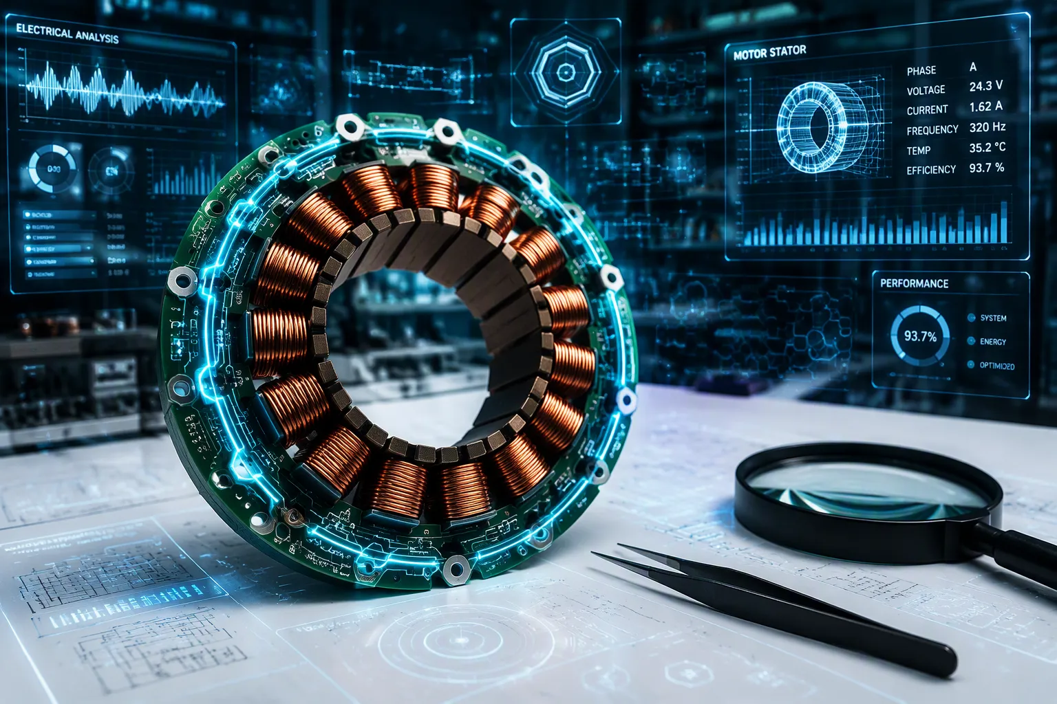
What is a PCB stator? It is a motor stator where the coils are copper paths printed on a circuit board instead of wire wound around iron cores. Picture it as a coil of wire flattened onto a circuit board. This is important today because the world needs motors that are lighter, smaller, and more efficient for electric devices.
Level | Weight Reduction |
|---|---|
Component level (stator) | Less than 10% of conventional weight (over 90% reduction) |
Machine level | Up to 50% |
Key Takeaways
PCB stators make motors lighter and smaller by using copper traces instead of heavy wire coils and iron cores.
They allow axial-flux motors to fit into thin, compact designs for drones and electric vehicles.
Controlling heat is the biggest problem, but liquid cooling helps PCB stators run at high power.
What Is a PCB Stator and How Does It Differ?
Defining the PCB Stator
A PCB stator swaps out the iron core and copper windings of a regular motor for conductive traces on a circuit board. To understand what is a printed circuit board stator, you start with its basic parts. Think of it as a coil of wire flattened onto a circuit board. The traces carry current to make magnetic fields, just like traditional wire coils do. Instead of bulky stator coils made of wound wire, you get flat copper on a board.
PCB Stator motors have a stator made up of a printed circuit board with conductive traces that replace copper wire used in conventional machines.
The coils in a pcb motor stator are made as copper traces on a PCB. The traces improve material placement by putting copper only where it is needed. This method removes heavy iron cores and bulky wire bundles. You get a much lighter part. This design skips heavy copper windings and uses precision-etched paths instead.
PCB Stator vs. Traditional Stator
Now compare this design to a traditional wound version. A regular unit uses copper wire wrapped around iron teeth. These parts are heavy and need lots of raw material. This design flips that approach. It uses flat copper layers etched into exact patterns. The missing iron and the smart copper layout make a huge difference.
How big is the difference? Motors using this approach weigh almost 50% less than competing solutions. The same design uses up to 80% less copper and other materials. The weight reduction comes from removing the iron core. You get better performance with fewer resources.
What about torque density? Some sources say these motors have high torque density and are up to 30% lighter than competing designs. This points to a better torque-to-weight ratio than traditional machines. However, coreless setups may have lower absolute torque density than designs with cores. The trade-off depends on your application.
This approach allows a new architecture called the axial-flux motor. In an axial flux design, magnetic flux flows parallel to the motor shaft instead of radially. This works well with the flat board shape. The stator and the rotor sit in a thin disc arrangement. You can build a brushless axial flux motor that is compact and efficient. The axial flux setup is a natural fit for flat form factors. An axial flux motor delivers high power in a slim package. Many axial flux designs now depend on this flat stator approach.
How a PCB Stator Is Built and Works
Materials and Layer Construction
A PCB stator is made from copper foil coils etched onto an epoxy-glass laminate base. The copper traces form the stator coils in flat spiral paths across several layers of a PCB. High-performance designs may use 4 oz copper or more than 4 oz copper to make thicker conductive paths. Some advanced builds stack 4–6 layers of 35–70 μm copper, connected with laser-drilled microvias.
A complete PCB motor has three main parts: the stator, the rotor, and the drive circuit. The stator holds the copper traces. The rotor holds the magnets. The drive circuit controls the flow of current. Manufacturers sometimes place ceramic inserts under hot zones to handle heat. They bond these inserts to the FR4 base with thermally conductive epoxy during lamination.
Working Principle and the Axial-Flux Motor
When current flows through the copper traces, it creates a magnetic field. This field interacts with the permanent magnets on the rotor. The force that results drives the rotor to spin. You control speed and torque by adjusting the current timing and strength. This is how a three-phase brushless motor works with a PCB stator.
PCB stators enable a new type of axial-flux motor. In an axial flux machine, magnetic flux flows parallel to the shaft. This flat shape fits the thin board perfectly. An air-core axial-flux permanent-magnet motor gains from this design because it removes the iron core completely. Designing the PCB stator coils for an axial flux brushless motor requires careful attention to trace width and layer count. The axial flux layout delivers high power in a slim package.
Advantages, Limits, and Real-World Uses
Pros and Cons of PCB Stators
A pcb stator gives you real benefits. The flat design makes the motor smaller and lighter. It uses much less copper and iron. Efficiency goes up because the motor wastes less energy. Some pcb motor designs also run with zero cogging. That smooth motion works well for haptic feedback and precision tasks.
Heat is the main problem. In compact axial-flux machines, it is hard to remove heat from the stator windings. The winding temperature limits current density and output. Engineers fix this with PCB-embedded windings and internal liquid-cooling paths. This puts thermal management closer to the heat source than outside jackets. Prototype tests reached trace-level operation above 100 A/mm². Models show about 19% less machine mass and 2.7 times more power than a baseline design. This work is still at TRL 4, so full motor demonstrations are still to come.
Common Applications
You can already find this technology in products you can buy. A commercial consumer product came to stores in Q4 2024. The Thrustmaster T598 direct-drive racing wheel launched in October 2024. That wheel uses a brushless platform with no gearbox. Every torque imperfection goes straight to your hands.
ECM's partnership with Thrustmaster produced the T598 direct-drive sim racing wheel, released to market in October 2024. A direct-drive racing wheel is one of the most demanding haptic applications in consumer electronics: with no gearbox between the motor and the driver's hands, every imperfection in torque output is felt immediately. The T598 demonstrates that ECM's zero-cogging platform can be taken from engineering concept to mass-produced commercial product.
Other uses include consumer electronics, fitness equipment, HVAC, e-mobility, medical devices, robotics, aerospace, and pumps. Fitness equipment also uses this design:
Smart rowing ergometer: an ECM motor-controller system copies the exact drag of a fan-based machine in software, with resistance profiles you can fully program and change.
Cable-driven weightlifting machine: programmable motor torque closely copies the feel of lifting a real weight.
Medical devices, pumps, and aerospace programs also aim at this technology. The axial flux layout fits any use that needs a thin, powerful motor.
So what is a PCB stator? It swaps iron cores and wire coils for copper traces on a circuit board. You get a lighter, compact motor, but heat management has trade-offs. This technology makes thin axial flux motors for EVs and aerospace applications. The axial flux design gives high power in a slim package. Think about a PCB stator for your next efficient motor project.
FAQ
How does a pcb motor stator handle heat?
Heat dissipation is the main challenge. The compact stator lacks iron to conduct heat away. Engineers use liquid cooling or ceramic inserts.
What role does the stator play in an axial flux motor?
The stator creates the magnetic field. In an axial flux design, it sits flat against the rotor. This enables a very thin motor.
Do pcb axial flux motors handle high torque?
They offer high torque density for their weight. You get good torque in a lightweight package. Absolute torque may be lower.
See Also
Exploring Printed Circuit Boards And Their Fundamental Ideas
Understanding The Base Materials In Circuit Board Construction
An Overview Of High Speed Printed Circuit Boards
Panasonic Copper Clad Laminates Used In Circuit Board Production
Comparing Fully In House Versus Partial In House Circuit Fabrication
