Why Choose Black Core PCB for High-Power and Heat-Sensitive Devices
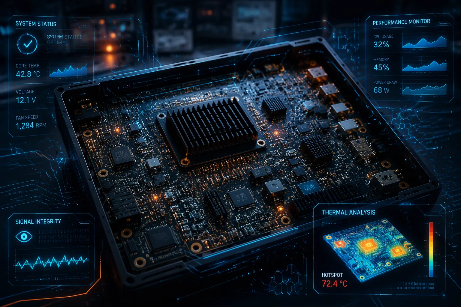
Black core PCB excels where standard boards fail. You need superior thermal conductivity and heat dissipation for high-power, heat-sensitive devices; this material delivers both. Ordinary PCBs trap heat. Solder joints crack. Sensitive circuits drift. Performance loss and reliability issues follow.
Black core PCBs solve these problems with a ceramic-filled substrate that spreads heat quickly and matches component expansion rates. Effective thermal management keeps your design safe under continuous load. Against FR-4, black core dissipates heat faster. Against metal core, it offers better electrical insulation and design flexibility. For demanding applications, black core provides the best balance of performance, reliability, and cost.
Key Takeaways
Black core PCBs use ceramic-filled substrates for superior heat dissipation.
They reduce component temperatures by 15–25°C compared to standard FR-4 boards.
Low thermal expansion matches component leads, preventing solder joint cracks.
High dielectric strength and low signal loss ensure stable electrical performance.
They support thicker copper layers, enabling higher current carrying capacity.
Black core PCBs allow smaller, denser designs without overheating.
They offer a cost-effective balance of thermal performance and reliability.
Choose black core PCBs for power converters, LED drivers, and motor controllers.
What Makes Black Core PCB Different
Black core PCB uses a specialized resin and ceramic-filled substrate. This is not just a black solder mask on standard material. The substrate combines ceramic fillers, epoxy resin, and reinforcing fibers. This unique composition delivers a balance of thermal, electrical, and mechanical properties. You get a material engineered for heat, not a cosmetic variation.
High Thermal Conductivity
Filler Materials and Heat Transfer
Ceramic fillers drive the heat transfer performance of black core PCBs. These fillers enable rapid heat movement away from power transistors and LEDs. The epoxy resin binds the ceramic particles and reinforcing fibers into a stable matrix. Carbon-based additives further tune the thermal path. This structure distributes heat efficiently and minimizes thermal hotspots across the board.
Conductivity Values vs. FR-4
Standard FR-4 manages only 0.2–0.4 W/m·K. Black core PCBs achieve 1.0–1.5 W/m·K. That difference matters when you run continuous high power. Higher thermal conductivity means heat leaves your components faster. The substrate also maintains a glass transition temperature of 180–220°C. This high Tg supports thermal stability under demanding loads.
Low Thermal Expansion
CTE Matching with Components
Black core PCBs exhibit low coefficient of thermal expansion. This range closely matches the CTE of component leads and solder joints. When temperatures rise, the board and components expand at similar rates. You avoid the mechanical mismatch that causes stress.
Reduced Mechanical Stress
Mismatched expansion creates stress on solder joints and component bodies. Black core PCBs reduce this stress through CTE matching. The result is fewer cracked joints and less mechanical fatigue. Your design survives thermal cycling with greater integrity.
Electrical Insulation and Stability
Dielectric Strength Under Heat
Black core PCBs maintain strong insulation properties at elevated temperatures. The table below compares key electrical parameters.
Electrical Property | Black Core PCB | Standard FR-4 PCB |
|---|---|---|
Insulation Resistance | >10¹⁴ Ω·cm | 10¹³–10¹⁴ Ω·cm |
Dielectric Strength | 25–30 kV/mm | 15–20 kV/mm |
Df (100MHz) | <0.02 | 0.02–0.03 |
Stable Performance Under Heat: With a Tg of 180–220°C, black core PCBs resist softening or warping in high-temperature environments (e.g., industrial enclosures or automotive engine bays). Key Takeaway — Electrical Stability: Low dielectric loss (Df <0.02) and high insulation resistance (>10¹⁴ Ω·cm) ensure signal integrity in high-voltage designs.
Long-Term Substrate Stability
Low dielectric loss and high insulation resistance ensure signal integrity in high-voltage designs. Black core PCBs resist softening or warping in hot environments. This stability supports thermal management across the product lifespan. You get a substrate that holds its electrical properties under continuous thermal load.
Thermal Management in High-Power Applications
Black core PCBs handle heat in ways standard boards cannot. You need efficient thermal management when your design runs continuous high current and heat loads. The substrate moves heat away from components through two primary pathways. This section explains how that process works and what it means for your power electronics designs.
Efficient Heat Dissipation Pathways
Vertical and Lateral Heat Spreading
Heat leaves a power component in two directions. Vertical spreading carries heat straight down through the substrate. Lateral spreading moves heat sideways across the board surface. Black core PCBs support both paths effectively. The ceramic-filled substrate conducts heat away from the component junction faster than FR-4. A metal core PCB uses a similar principle. A thin dielectric bonds a copper layer to a thick metal plate. Heat travels vertically through the dielectric to the metal, which then spreads it laterally. Black core PCBs achieve comparable vertical and lateral spreading without a metal plate. The ceramic filler creates a continuous thermal path through the substrate thickness. This design eliminates the need for thermal vias in many layouts. You get direct heat transfer from component to board to heat sink.
Reduced Hot Spots
Hot spots form when heat cannot leave a small area fast enough. Black core PCBs reduce hot spot formation through high thermal conductivity. The table below shows how ceramic substrates compare to standard FR-4 under continuous load.
Benchmark | FR-4 (Standard PCB) | Ceramic Substrates |
|---|---|---|
Thermal conductivity | 0.3–0.8 W/mK | 20 to >200 W/mK |
Power density / heat flux handling | <100 W/cm² (exceeds capability) | Capable of handling >100 W/cm² |
Thermal resistance (junction-to-ambient) | Often exceeds acceptable limits | Significantly lower |
You can see the difference clearly. FR-4 struggles above 100 W/cm². Ceramic substrates handle that heat flux without difficulty. Lower thermal resistance means heat moves from junction to ambient more efficiently. Your components run cooler and more uniformly.
Higher Current Carrying Capacity
Thermal Limits of Copper Traces
Copper traces carry current and generate heat. The trace temperature depends on current density and the board's ability to remove heat. Black core PCBs support thicker copper layers than standard FR-4. You can use 3–6oz copper, which handles up to 100A in a 5mm trace. FR-4 struggles with 2oz copper and above. A 50A EV BMS design uses 4oz copper traces to reduce trace width by 50%. That saves board space and improves power density. The substrate's thermal conductivity keeps those traces cooler under load.
Safe Operation at Elevated Temperatures
Black core PCBs maintain structural integrity at high operating temperatures. The glass transition temperature ranges from 180–220°C. FR-4 typically reaches only 130–170°C. This higher Tg means the board resists softening and warping during continuous high-power operation. You can run power electronics closer to their thermal limits without risking substrate failure. The flexural strength of 300–350 MPa also withstands vibration in motor controllers and automotive applications. Safe operation at elevated temperatures extends to the solder joints. The low CTE of black core PCBs reduces stress on joints during thermal cycling.
Improved Power Density
Smaller Form Factors Without Overheating
Higher thermal conductivity enables smaller designs. You can pack more power into less board space when heat leaves quickly. Black core PCBs reduce component temperatures by 15–25°C compared to FR-4. That reduction directly prevents overheating in compact designs. A 300W industrial power supply using black core PCB maintains 75°C versus 95°C with FR-4. The lower temperature allows you to shrink the heat sink or eliminate active cooling entirely. Thermal vias in a 10mm×10mm BGA with 20 vias of 0.3mm diameter provide 2x more heat dissipation. This enhances vertical heat paths for dense power layouts.
Examples in Power Converters and LED Drivers
Power converters benefit from black core PCB thermal management. UPS systems achieve 95%+ efficiency in 1–10kVA ranges. Solar inverters reach 98% conversion efficiency due to reduced heat-related losses. LED drivers see similar gains. A 100W LED module saw junction temperature reduced by 20°C. That reduction extended lifespan from 30,000 to 50,000 hours. High-brightness LEDs for streetlights and stadium lighting manage thermal buildup for consistent brightness. Motor controllers also benefit. Motor drives and VFDs handle 200–500A currents without overheating. A mining equipment manufacturer reported a 70% drop in vibration-related failures after switching to black core PCBs. Welding equipment maintains stability during arc welding at 100–500A. These examples show how black core PCBs enable higher power density across applications.
Why Black Core PCB Excels in High-Power Applications
Reduced Thermal Stress on Components
Lower Temperature Rise at Junctions
Black core PCBs reduce component temperatures by 15–25°C compared to FR-4. This drop directly lowers junction temperatures in high-power electronics. You get cooler operation without adding active cooling. A 300W industrial power supply using black core PCB maintains 75°C versus 95°C with FR-4. That 20°C difference extends component life and prevents thermal runaway.
Protection for Sensors and Analog Circuits
Heat-sensitive applications demand stable temperatures for accurate readings. Sensors and analog circuits drift when heat builds up. Black core PCBs keep those components within their optimal range. You protect signal integrity in measurement and control systems. This protection matters in medical devices and precision instrumentation.
Enhanced Reliability and Lifespan
Slower Solder Joint Degradation
Solder joints crack under repeated thermal expansion and contraction. Black core PCBs use low CTE materials that match component leads. This match reduces mechanical stress on joints during temperature swings. You get slower degradation and fewer field failures. The result is a longer operational lifespan for your product.
Stable Performance Over Thermal Cycles
Black core PCBs maintain stable electrical and mechanical properties across thermal cycles. The glass transition temperature of 180–220°C resists softening. You avoid warping and delamination that plague standard boards. This stability ensures consistent performance in high-power applications. Your design operates reliably from first power-up to end of life.
Suitability for Medical and Automotive Electronics
Examples in Patient Monitoring and ECUs
Medical patient monitoring devices require precise thermal control. Black core PCBs manage heat dissipation in compact enclosures. Automotive systems rely on these boards for engine control units and power modules. A mining equipment manufacturer reported a 70% drop in vibration-related failures after switching to black core PCBs. These examples show broad suitability across demanding sectors.
Compliance with Thermal Reliability Standards
Black core PCBs help you meet thermal reliability standards for automotive systems and medical devices. The substrate withstands rigorous thermal cycling tests. You can design to IPC and AEC-Q standards with confidence. This compliance reduces certification risk and speeds time to market.
Key Takeaway — Thermal management with black core PCBs delivers lower junction temperatures, stable performance, and compliance with industry standards for high-power electronics.
Black Core PCBs vs. Standard FR-4
Thermal Performance Comparison
Conductivity and Heat Dissipation Rates
Standard FR-4 manages only 0.2–0.4 W/m·K. Black core PCBs achieve 1.0–1.5 W/m·K. That difference directly affects how fast heat leaves your components. Higher thermal conductivity means heat moves through the substrate more efficiently. You get faster heat dissipation and lower operating temperatures.
The table below summarizes the thermal gap between these two materials.
Parameter | Black Core PCBs | Standard FR-4 |
|---|---|---|
Thermal Conductivity | 1.0–1.5 W/m·K | 0.2–0.4 W/m·K |
Glass Transition Temp | 180–220°C | 130–170°C |
CTE | 10–14 ppm/°C | 14–17 ppm/°C |
Black core PCBs maintain stable thermal management across continuous loads. FR-4 struggles when power density rises above 100 W/cm².
Temperature Rise Under Identical Loads
A 300W industrial power supply using black core PCBs maintains 75°C. The same design with FR-4 reaches 95°C. That 20°C difference extends component life and prevents thermal runaway. Black core PCBs reduce component temperatures by 15–25°C compared to FR-4. You avoid hot spots and keep sensitive circuits within safe limits.
Reliability Under Thermal Cycling
Cracking and Delamination Resistance
FR-4 expands and contracts more than black core PCBs during thermal cycles. This mismatch stresses solder joints and causes cracking. Black core PCBs use low CTE materials that match component leads. The result is fewer cracked joints and less delamination. Your design survives repeated temperature swings with greater integrity.
MTBF Differences
Black core PCBs deliver longer mean time between failures than FR-4. Lower junction temperatures slow solder joint degradation. Stable substrate properties prevent warping and electrical drift. A 100W LED module saw lifespan extended from 30,000 to 50,000 hours after switching to black core PCBs. You get reliable performance from first power-up to end of life.
Cost and Manufacturing Considerations
Material Cost vs. Long-Term Savings
Black core PCBs cost more per square meter than FR-4. The ceramic-filled substrate demands a higher initial investment. You recover that cost through reduced failure rates and fewer field returns. Lower cooling requirements also cut system costs. A smaller heat sink or passive cooling saves money and board space.
Availability and Fabrication Complexity
Black core PCBs require specialized fabrication processes. You need controlled lamination and precise drilling parameters. Not every PCB shop offers this material. Lead times may run longer than standard FR-4 orders. However, the performance gains justify the added complexity for high-power designs. You should verify supplier capability before committing to production.
Black Core PCBs vs. Metal Core PCBs
Metal Core PCB Thermal Conductivity vs. Black Core
Heat Transfer Efficiency Comparison
Metal core pcbs win on raw heat transfer. Their metal base layer, usually aluminum or copper, delivers high metal core pcb thermal conductivity. Black core pcbs reach 1.0–1.5 W/m·K. That gap matters at extreme power densities. An insulated metal substrate pcb pushes heat straight through a thin dielectric into a thick metal plate. Black core pcbs spread heat through ceramic fillers instead. You get lower thermal conductivity, but you also avoid the parasitic capacitance that metal core pcbs introduce. For most high-power designs, black core pcbs deliver enough thermal management without the electrical penalties.
Weight and Mechanical Integration
Aluminum pcbs and copper core pcbs add significant mass. A thick aluminum pcb plate makes your assembly heavier and harder to mount in compact enclosures. Black core pcbs use standard FR-4-like thickness and weight. You can integrate them into existing mechanical designs without redesigning brackets or standoffs. Copper core pcbs offer excellent heat spreading, but their weight limits use in portable or vibration-sensitive products. Black core pcbs give you a lighter option that still handles continuous thermal loads.
Electrical Insulation and Design Flexibility
Dielectric Isolation Differences
Metal core pcbs rely on a thin dielectric layer for isolation. That layer limits breakdown voltage and adds capacitance. An insulated metal substrate handles high voltage, but the dielectric constrains your design. Black core pcbs use a ceramic-filled resin that provides dielectric strength of 25–30 kV/mm. You get better isolation without a separate insulating layer. This difference simplifies mcpcb design principles and reduces layer count.
Routing Density and Layer Count Options
Aluminum pcb and copper core pcb options typically support single-sided or simple double-sided layouts. Mcpcbs restrict routing density because the metal base is conductive. Black core pcbs support multilayer stackups. You can route signals on multiple layers and place components on both sides. This flexibility makes mcpcb design easier for complex circuits. IMS pcbs and IMS pcb design work well for simple LED arrays, but black core pcbs handle dense power converters and control circuits.
Cost and Application Fit
When Metal Core Is Overkill or Insufficient
Metal core pcbs cost more than black core pcbs. You pay for the aluminum or copper base and the specialized dielectric. For designs below 100 W/cm², metal core pcb thermal conductivity exceeds your needs. You waste money on heat transfer you cannot use. Conversely, metal core pcbs fall short when you need multilayer routing or high dielectric isolation. Mcpcbs cannot match black core pcbs in electrical complexity.
Best Use Cases for Black Core PCB
Choose black core pcbs for power converters, LED drivers, and motor controllers. These applications need solid thermal conductivity, low CTE, and multilayer routing. Black core pcbs deliver all three at a lower cost than metal core pcbs. You also get better design flexibility for mcpcb design and copper core pcb options. When your design demands both heat dissipation and electrical performance, black core pcbs provide the best fit.
Cost, Reliability, and When to Choose Black Core PCB
Total Cost of Ownership
Initial Price vs. Failure Rates
Black core pcbs cost more per square meter than standard FR-4. You pay a premium for the ceramic-filled substrate. That upfront price tells only part of the story. Field failures drive warranty claims, returns, and reputation damage. Lower junction temperatures slow solder joint degradation. You recover the material premium through fewer field returns over the product lifespan.
Savings from Reduced Cooling Requirements
A 300W industrial power supply using black core pcbs maintains 75°C versus 95°C with FR-4. That 20°C difference lets you shrink the heat sink or eliminate active cooling entirely. You save on fan assemblies, thermal interface materials, and enclosure volume. These savings compound across production volume. Efficient thermal management reduces system-level costs beyond the board itself.
Reliability Data and Field Performance
Accelerated Life Testing Results
Black core pcbs maintain stable electrical and mechanical properties across thermal cycles. The glass transition temperature of 180–220°C resists softening and warping. A 100W LED module saw lifespan extended from 30,000 to 50,000 hours after switching to black core pcbs. Accelerated testing confirms slower degradation under continuous thermal load.
Case Studies in High-Power and Heat-Sensitive Devices
A mining equipment manufacturer reported a 70% drop in vibration-related failures after switching to black core pcbs. Solar inverters reach 98% conversion efficiency due to reduced heat-related losses. Medical patient monitoring devices benefit from stable temperatures in compact enclosures. These heat-sensitive applications demand the thermal management that black core pcbs deliver.
Decision Checklist for Engineers
Key Parameters to Evaluate
You should assess several parameters before selecting a substrate. Power density above 100 W/cm² rules out standard FR-4. Thermal conductivity requirements above 0.4 W/m·K point toward black core pcbs. Multilayer routing needs eliminate most metal core pcbs. Dielectric strength above 20 kV/mm favors black core pcbs over mcpcbs. Evaluate your CTE matching needs against the 10–14 ppm/°C range.
When Black Core Is the Clear Choice
Black core pcbs fit power converters, LED drivers, and motor controllers. You need solid heat dissipation, low CTE, and multilayer routing. Mcpcbs cannot match this electrical complexity. Metal core pcbs cost more and restrict routing density. When your design demands both thermal conductivity and electrical performance, black core pcbs provide the best fit. Mcpcbs work for simple LED arrays below 100 W/cm². Black core pcbs handle dense power circuits with heat-sensitive components.
Key Takeaway — Black core pcbs deliver lower total cost of ownership through reduced cooling needs and fewer failures, making them the clear choice for demanding thermal applications.
Black core PCBs earn their place in high-power designs through three strengths. First, superior thermal conductivity moves heat away from sensitive components. Second, low thermal expansion matches component leads and reduces mechanical stress. Third, stable electrical insulation protects sensors and analog circuits under continuous load.
For high-power and heat-sensitive devices, black core PCBs offer the best balance of performance, reliability, and cost. You get cooler junctions, longer lifespan, and fewer field failures. Metal core PCBs cost more and restrict routing. Standard FR-4 cannot handle the heat.
Evaluate your thermal requirements early. Check power density, CTE needs, and dielectric strength. When your design demands both heat dissipation and electrical performance, black core PCBs are the clear choice.
FAQ
What thermal conductivity can you expect from black core pcbs?
Black core pcbs deliver 1.0–1.5 W/m·K, versus 0.2–0.4 W/m·K for FR-4. Heat leaves components faster. That gap matters above 100 W/cm² power density.
How does thermal expansion compare to standard boards?
Black core pcbs match component leads with 10–14 ppm/°C CTE. Standard FR-4 runs 14–17 ppm/°C. Matching reduces mechanical stress on solder joints. Your board survives thermal cycling without cracking.
Can you use these boards for multilayer designs?
Black core pcbs support multilayer routing and double-sided placement. Aluminum pcbs typically restrict layouts to single-sided designs. Dense power converters need that routing freedom. You can separate signals from high-current traces.
When is metal core a better fit?
Metal core pcbs offer high thermal conductivity, but add weight and parasitic capacitance. Designs below 100 W/cm² gain nothing from that extra heat transfer. Black core pcbs handle those loads at lower cost. Choose metal core only for extreme power density.
Do black core pcbs increase board cost?
Yes. The ceramic-filled substrate costs more per square meter than FR-4. You recover the premium through fewer field failures, smaller heat sinks, and longer product lifespan. Total ownership cost usually drops.
Which reliability standards do they support?
Black core pcbs help you meet IPC and AEC-Q thermal cycling requirements. A 100W LED module extended lifespan from 30,000 to 50,000 hours after switching. Slower solder joint degradation explains that result.
What signs indicate you need black core pcbs?
Power density above 100 W/cm², thermal conductivity needs above 0.4 W/m·K, or dielectric strength above 20 kV/mm. Check these three parameters before selecting substrate. You will avoid over-specifying with metal core.
