Copper Thickness for PCB Stators
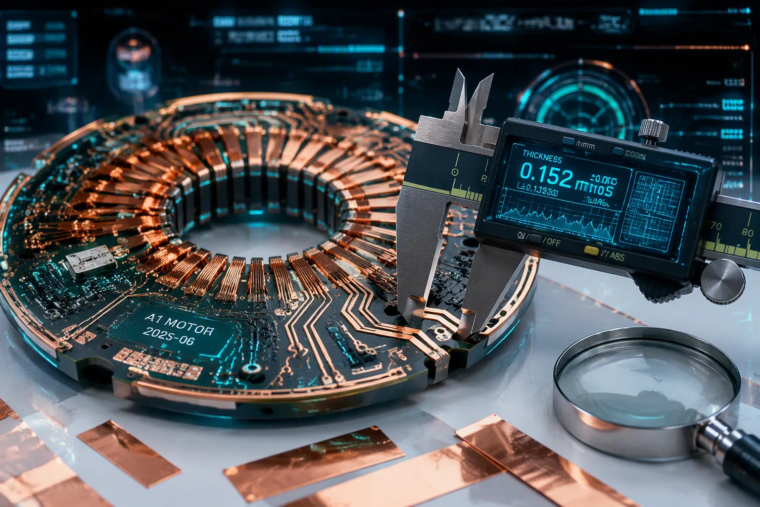
For most PCB stators, a copper thickness of 2 oz (70 µm) to 4 oz (140 µm) is recommended. But the best choice depends on current and thermal constraints. This matters because PCB stators already use far less copper than conventional motors.
PCB stators require only 20% of the copper compared to conventional wound stators.
That savings makes thickness selection even more critical for efficiency. This article explains why copper thickness matters. It includes eddy current losses at ultra-thin foils. It covers key factors such as current, heat, and cost. It also reviews common options from 1 oz to 4 oz, plus the 25 µm plating limitation. A step-by-step selection guide helps engineers choose wisely.
Key Takeaways
A 2 oz to 4 oz copper thickness balances resistance and heat for most PCB stators.
Thicker copper carries more current, but it raises eddy current losses at high frequency.
Ultra-thin foil around 12 µm lowers eddy currents; use parallel layers to keep resistance low.
Thick copper needs wider trace widths, which limits winding density and raises cost.
Match copper thickness to the current, heat, and frequency. Use simulation tools early on.
Why Copper Thickness Matters
Copper thickness affects almost every part of how a PCB stator works. It controls resistance, current capacity, heat flow, and energy loss. Engineers must not ignore it.
Resistance and Current Capacity
A thicker copper layer gives electrons a wider path. That wider path cuts electrical resistance. Lower resistance lets the stator carry more current without overheating. IPC-2152 shows the direct link between copper foil thickness and current capacity. For example, a 1 oz copper trace that is 10 mil wide can carry around 1.2 A with a 10 °C temperature rise. The same trace made of thicker copper handles much more current. Published data says 0.5 oz copper tops out near 11 A, 1 oz near 19 A, 2 oz near 26 A, and 3 oz near 33 A. These numbers come from specific test conditions, but the pattern is clear. More copper means more current.
The relationship also works in reverse. For a set current, thicker copper allows a narrower trace. A 10 A load at 4 A/mm² needs 35.7 mm width in 2 oz copper. The same current in 1 oz copper needs a wider trace. This matters because PCB stators already use 20% less copper than normal wound stators. Every micron of copper foil trace has to work harder. A poor thickness choice wastes that benefit.
Thermal Behavior and Eddy Current Losses
Heat and frequency pull in opposite directions. Thicker copper spreads heat better and lowers DC resistance. But thicker copper also raises eddy current losses. Eddy currents swirl inside the conductor when the stator drive switches at high frequency. These currents make heat without creating torque. The effect gets worse as copper gets thicker.
Ultra-thin copper foil, around 12 µm, cuts eddy currents greatly. High-speed PCB motors often use this foil to keep AC losses low. The trade-off is higher DC resistance and lower current capacity. Designers of PCB coils must balance these two forces. A PCB stator winding for a low-speed fan works differently from one in a high-speed spindle. The winding copper fill factor and copper fill factor also change with thickness. More copper fill boosts torque density, but only if heat limits allow it.
Key Factors for Copper Thickness in PCB Stators
Current Demands and Thermal Budget
Current needs drive the first choice. A PCB stator has to handle peak current without getting too hot. A common problem comes from 25 µm plating. This thin layer makes heat build up in small spots. That lowers efficiency and shortens the stator's life. Multi-layer circuit boards can help. They spread current across several inner layers. This lowers the heat stress on any one trace. The trace temperature stays even.
Each inner layer shares the current load. This keeps any single trace from getting too hot. This method works well for high-current designs. But it adds more layers and raises lie-making cost. Designers have to weigh this trade-off. The 25 µm plating layer can hit its heat limit at high switching frequencies. This limit cuts the useful current capacity. Designers should check the heat profile with simulation tools.
The heat budget links straight to the weight of the copper layer. Thicker copper pulls more heat away from the coils. This lets the motor run cooler. A bigger budget gives engineers room for higher power densities. It also makes the motor more reliable over long use. The pcb layout must spread heat evenly across layers. The copper itself must be thick enough to carry the current.
Cost, Layer Count, and Manufacturing Limits
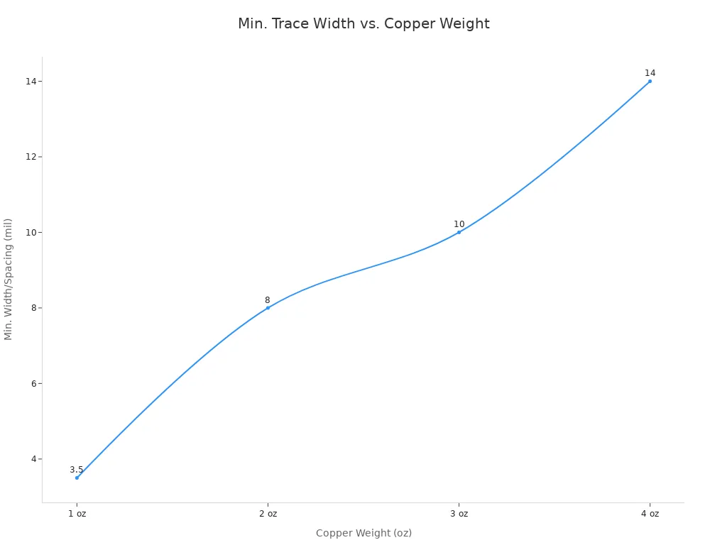
Cost goes up sharply above 2 oz material. A 3 oz layer needs more etching steps. Trace width must also grow. The table below shows the smallest trace width and spacing for each weight.
Copper Weight | Min. Recommended Trace Width / Spacing |
|---|---|
1 oz | 3.5 mil (0.089 mm) |
2 oz | 8 mil (0.203 mm) |
3 oz | 10 mil (0.254 mm) |
4 oz | 14 mil (0.355 mm) |
These values force design trade-offs. A designer cannot fit fine-pitch traces. For a 4 oz layer, the width jumps to 14 mil. This limits the number of turns per layer. A designer may need more layers to get the same winding density. This raises cost and complexity. The pcb manufacturing precision requirement gets stricter as material gets heavier.
Standard etching handles up to 3 oz material well. Past that, special methods raise cost. The etch factor needs careful compensation. A wider trace can ensure accurate widths. A 4-layer board with 2 oz material may cost less than a 6-layer board with 1 oz material. The trade-off depends on the current density you need.
The copper thickness uniformity across layers also becomes critical. Variation causes uneven current distribution. This affects reliability in pcb motors. Designers must keep each layer within tight tolerances. The minimum trace width must be several times the copper thickness for reliable results.
Minimum trace width must be several times the copper thickness. This doesn't usually affect 2 oz proto boards (7/7 rule). 3 oz+ may need wider rules.
Fabrication for pcb motors demands attention to these constraints. A pcb motor with 4 oz on one layer and 2 oz on another causes problems. The copper foil on the thick layer undercuts more during etching. This reduces pcb manufacturing precision. The copper foil choice affects every step, from lamination to final inspection. Early consultation with the board house prevents costly redesigns. The pcb must be designed with these limits in mind.
Standard and Thick Copper PCB Options for Stators
Low to Moderate Current Applications
Most PCB stators start with 1 oz or 2 oz copper. A 1 oz layer measures 35 µm thick. A 2 oz layer measures 70 µm. These weights suit low to moderate current demands. They also work well for designs that need fine trace widths.
A 2 oz layer is the standard internal layer for a 3 oz finished board. Fabricators plate additional copper on the outer layers to reach the final weight. This approach gives designers a balance. The inner layers carry current with low resistance. The outer layers handle the final thickness requirement.
A 1 oz copper foil works for small fan motors and low-power sensors. These applications draw modest current. Heat generation stays low. The thin foil also allows tighter trace spacing. Designers fit more turns into the same board area. This boosts the copper fill factor without adding layers.
A 2 oz layer handles more current than 1 oz. It also spreads heat better. Many printed circuit board coils for medium-power PCB motors use 2 oz inner layers. The resistance drops compared to 1 oz. The eddy current losses stay manageable at moderate switching frequencies. This makes 2 oz a practical default for many stator designs.
High-Current and Demanding Designs
High-current stators need 3 oz or 4 oz copper. A 3 oz layer measures 105 µm. A 4 oz layer measures 140 µm. These weights lower DC resistance sharply. They let the stator carry more current without excessive heat.
The trade-off is eddy current loss. A thicker copper foil gives eddy currents more material to swirl in. At high switching frequencies, these losses grow. The extra heat cancels some of the DC resistance benefit. Designers of heavy copper designs must weigh both effects.
Segmented coil designs help here. Instead of one continuous winding, the stator uses separate coil segments. Each segment carries current over a shorter path. This reduces the loop area for eddy currents. The AC losses drop. The DC resistance stays low because the copper is still thick.
A thick copper pcb for a high-speed spindle motor may use 3 oz or 4 oz layers. The designer splits the winding into segments. This keeps AC losses in check. The stator runs cooler and more efficiently.
A 3-6oz copper weight pcb gives engineers room for high current. But the minimum trace width grows. A 4 oz layer needs 14 mil trace width and spacing. This limits turns per layer. The designer may need more layers to reach the target winding density. The copper weight pcb choice affects cost, layer count, and thermal performance.
The table below summarizes the common options.
Copper Weight | Thickness | Typical Use |
|---|---|---|
1 oz | 35 µm | Low-current fans, sensors |
2 oz | 70 µm | Medium-power PCB motors |
3 oz | 105 µm | High-current stators |
4 oz | 140 µm | Demanding, high-torque designs |
Engineers should match the copper thickness to the application. A low-RPM fan motor rarely needs more than 2 oz. A high-speed spindle motor may need thin foil with parallel layers. The right choice depends on current, heat, and frequency.
Selecting Copper Thickness for PCB Stators
Step-by-Step Decision Process
Engineers can use a simple process to pick the right copper thickness for a PCB stator design. Each step leads to the next one.
Find the highest DC current. The designer looks at the biggest current the stator will carry during normal use. This value sets the starting point for all later choices.
Decide how much heat is okay. The designer checks the thermal budget for the application. A 10 °C rise works for many designs, but some need tighter limits. The 25 µm plating layer can get too hot at high switching speeds. This step catches that problem early.
Look at eddy current effects based on switching frequency. Higher frequencies create more eddy currents in thick copper. The designer compares the AC loss to the DC resistance benefit. Copper foil that is too thick wastes energy as heat.
Check the PCB stackup and via compatibility. The designer confirms if the board uses single, double, or multiple layers. Multi-layer boards spread current across inner layers. This lowers heat stress on any one trace. The designer also makes sure vias can handle the current without adding more resistance.
After these steps, the designer checks current density distribution. This check shows if current flows evenly through the copper. Uneven flow creates hot spots and lowers reliability. The designer may change trace width or layer count to fix problems. The coil routing design also affects how current spreads. A bad routing pattern forces current into narrow paths. This raises heat in small areas and lowers efficiency.
Application Examples (Low‑RPM vs. High‑RPM)
A low-RPM fan motor shows how simple the choice can be. This PCB motor draws small current at low switching speed. Eddy currents stay small. A 2 oz copper layer can handle the load without issues. The designer keeps the stackup simple and avoids extra layers. The 70 µm copper gives low resistance and good heat spreading. The PCB manufacturing precision stays relaxed. Standard trace widths work fine.
A high-speed spindle motor tells a different story. This PCB motor runs at high switching speed. Eddy currents grow quickly in thick copper. The designer may choose ultra-thin copper foil around 12 µm to lower AC losses. But thin foil raises DC resistance. The solution uses parallel layers. Several thin layers carry current together. This keeps resistance low while limiting eddy currents. The PCB manufacturing precision must be tight. Thin foil needs careful handling during fabrication. The stator runs cooler and more efficiently as a result.
These two examples show that no single answer works for every case. The designer must match copper thickness to the real operating conditions. A low-RPM fan motor rarely needs more than 2 oz. A high-speed spindle motor may need thin foil with parallel layers. The right choice depends on current, heat, and frequency together.
Engineers should see 2–4 oz copper as the usual best range for PCB stators. The final pick still depends on balancing DC resistance, heat limits, and eddy current losses. Designers must keep in mind the 25 µm plating limit, which can cause local heating. For high-frequency work, ultra-thin copper foil near 12 µm gives a proven way to lower AC losses. Thermal simulation tools help check each option before you commit. Talking with PCB fabricators early stops costly redesigns later. Picking the right thickness lets PCB motors keep their efficiency edge. That edge matters, since PCB motor technology already uses 20% less copper than normal wound designs.
FAQ
What is the risk of 25 µm plating in stator designs?
The 25 µm plating layer makes hot spots when switching at high speed. This thin layer holds heat in small areas. Designers should check the PCB heat profile early to avoid problems.
When does ultra-thin foil help PCB motors?
Ultra-thin foil helps PCB motors in high-speed spindle motors. The thin foil, about 12 µm, lowers eddy current losses at high frequency. Designers use parallel layers to keep DC resistance low.
How does layer count affect cost for PCB motors?
A 4-layer board with 2 oz copper costs less than a 6-layer board with 1 oz copper. More layers spread the current but raise fabrication cost. Designers balance current need against total cost.
Should engineers use thermal simulation tools?
Yes. Thermal simulation tools check heat spread before making the board. The 25 µm plating risk and eddy current losses change the temperature. Early simulation helps avoid expensive redesigns.
How much copper do PCB stators save?
PCB stators use only 20% of the copper that normal wound stators need. This saving makes choosing the right thickness very important for efficiency.
See Also
Key Advice For Engineering High Current Heavy Copper Boards
Manufacturing Process Overview For Thick Copper Multilayer Boards
Using Panasonic Copper Clad Laminates In Circuit Board Fabrication
How Vertical Continuous Plating Affects Copper Thickness Uniformity
Seven Vital Quality Checks For Building Heavy Copper Auto Boards
