High-Speed PCB for Data Center Server Applications
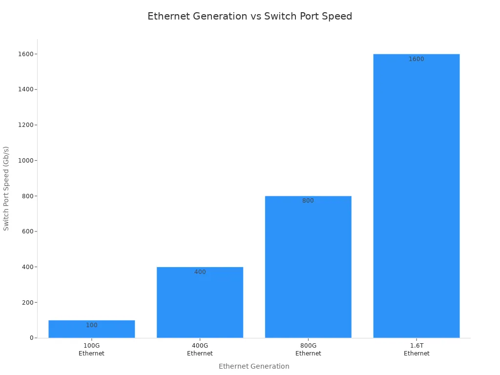
You need to watch for many important things when you design a high-speed PCB for a data center. Signal integrity is the main thing for moving data safely at speeds up to 1.6 Tb/s, as you can see in the table below.
Ethernet generation | Switch port speed | Typical SerDes signaling |
|---|---|---|
100G Ethernet | 100 Gb/s | 25G NRZ |
400G Ethernet | 400 Gb/s | 56G PAM4 |
800G Ethernet | 800 Gb/s | 112G PAM4 |
1.6T Ethernet | 1.6 Tb/s | 224G PAM4 (emerging) |
You must also manage power delivery with thick copper planes and tricky PDN structures. Advanced materials help lower signal loss, which matters more at higher frequencies. Every choice changes how well the system works, how reliable it is, and how it can grow later.
Use the best design plans for your needs. Each choice helps decide how well your data center systems will do.
Key Takeaways
Make sure signals stay strong for fast data transfer. Use special materials and careful paths to stop mistakes.
Use thick copper layers and enough layers for power. This keeps voltage steady and cuts down on noise.
Stop electromagnetic interference by using solid ground layers. Do not make big loops in the paths. This keeps signals clear and safe.
Pick the best materials for high-speed PCBs. Low-loss laminates make signals better, especially when speeds are high.
Think about the future by using designs and connectors you can change. This makes it easy to upgrade and add more to your data center.
High-Speed PCB Challenges in Data Centers
Signal Integrity and SerDes
Designing high-speed PCBs for data centers is hard. Signal integrity is a big problem. Fast data makes signals go to high frequencies. Small mistakes can cause big errors. Logic gates and flip-flops may not work fast enough. This can cause timing problems. Clock skew means signals arrive at different times. It is hard to keep everything together. Interconnects act like transmission lines. If impedance does not match, reflections happen. Reflections hurt signal integrity. You also need to watch for crosstalk, attenuation, jitter, and dielectric loss. SerDes technology helps move signals between chips. Faster SerDes, like PAM4 for 400G and 800G Ethernet, need more care. You must handle lower signal-to-noise ratios and more channel loss. Advanced equalization and pre-emphasis help keep bit error rates low. They also keep signal integrity high.
Power Delivery and Layer Count
Power delivery is another big challenge. You must give power at low voltages, often around 1V, right to the chips. Thick copper planes are needed. Careful planning stops noise and ground bounce. High layer counts help route signals and power lines. This is needed for high-speed interfaces like Ethernet, PCIe, CXL, and memory. More layers give better signal isolation. They also improve power distribution and make impedance control easier. Extra layers let you fit more parts and manage heat better.
EMI and Dense Routing
Electromagnetic interference (EMI) is a problem when you pack many traces close together. Continuous ground planes give signals a safe return path. They help reduce EMI. Routing signals over split planes makes loops. Loops act like antennas and make more noise. Dense routing makes it hard to keep traces apart. This increases crosstalk and hurts signal integrity. You need to plan your layout well. Avoid big loops and use filtering with decoupling capacitors. Good EMI control helps your server pass strict tests. It keeps your high-speed PCB working well.
PCB Types and Requirements for Data Centers
Backplane and Storage PCBs
Backplane and storage PCBs are very important in data centers. These boards link server blades, switches, and storage devices together. Backplanes must work with high-speed interfaces and move lots of data. You need to pick materials that do not lose much signal. This helps data move fast and without mistakes. Storage PCBs use almost the same materials and number of layers. Both types need careful plans for power and signal paths. Always check impedance control and make sure grounding is strong. This helps stop signal problems.
HDI and AI Server Boards
AI servers use HDI boards with many layers and connections. These boards fit lots of parts into a small space. They support CPUs, GPUs, and memory systems. You have to control heat, keep signals good, and fit everything tightly. The table below shows what AI servers and network switches need:
PCB modules | Primary function | Typical layer count | PCB technologies | Interface types | Material requirements |
|---|---|---|---|---|---|
AI server motherboards (with GPU accelerator) | Host CPUs, GPUs, memory subsystems, and accelerator interconnects | 24–40+ | HDI | High-speed SerDes | Low-loss or very-low-loss laminates |
Network switch | Connect servers through high-speed switching fabrics and interface with network interface cards (NICs) | 24–36+ | HDI | Ultra-high-speed SerDes (112G/224G) | Ultra-low-loss materials for 112G/224G |
There are three big problems with AI servers and HDI boards:
Challenge | Description |
|---|---|
Thermal Management | Needs good ways to get rid of heat using special materials and designs. |
Signal Integrity | Makes sure signals stay strong even with lots of parts and wires. |
High-Density Interconnects | Needs small designs to fit many parts without problems. |
You should work on these things to keep your AI servers working well in a data center.
Connectors and Integration
You need to pick the best connectors for high-speed PCBs. Good connectors help signals stay strong and support fast speeds. You also need to plan how to connect with other systems like switches and storage. Good planning helps you grow your data center and add more AI servers later. Always test connectors to make sure they last and keep signals good. This keeps your data center working well and ready for the future.
Design Guidelines for High-Speed PCBs
Stack-Up and Impedance Control
When you design a high-speed pcb, you must plan the stack-up well. If the stack-up is even on both sides, the board will not bend during soldering. Using solid reference planes helps keep impedance steady. The 20H rule tells you where to put power planes to lower EMI. Pick materials that have the same dielectric constant everywhere. This keeps impedance the same across the board, which helps signal integrity.
If you plan your layers well, signals move faster and stay strong. Server motherboards often have 8 to 16 layers because they need many connections.
Here are some steps to help with impedance and stack-up:
Change the thickness of the dielectric to control impedance.
Do not put fast signals over split planes.
Use ground vias to give signals a good return path when they change layers.
The table below shows how each method helps signal integrity:
Technique | Impact on Signal Integrity |
|---|---|
Controlled Impedance | Stops reflections at interfaces and keeps signals smooth. |
Stackup Planning | Makes fields predictable and keeps impedance steady, so signals stay strong. |
Vias Management | Lowers impedance problems and makes signals more reliable with careful design. |
EMI and Crosstalk Control | Cuts down on interference and makes signals better. |
Verification and Validation | Checks if designs work right and are reliable by testing. |
Power and Ground Design
You need to make power and ground planes carefully in a high-speed pcb. Put decoupling capacitors close to power pins to give quick current and stop voltage drops. Place bypass capacitors near ICs to lower loop inductance. Solid ground planes and enough vias help current flow and keep impedance low.
Try these ideas for power and ground design:
Put decoupling capacitors near power pins.
Place bypass capacitors close to ICs.
Keep ground planes solid and use enough vias.
Run PDN simulations before making the board.
Use many power and ground vias to make more paths for current.
Good power and ground design gives you steady voltage rails. This is very important for signal integrity in high-speed pcb designs. If there is noise in the power network, it can mess up signals and cause errors. Managing power well makes your data center systems more reliable and easier to grow.
Routing and Crosstalk Management
You must manage routing and crosstalk to keep signals strong. Use controlled impedance of 50Ω or 75Ω to stop reflections. Make the layer stack-up right for fast signals. Balance trace width and spacing to keep impedance steady and lower crosstalk. Materials like polyimides can help the board work better.
Here are some ways to manage routing and crosstalk:
Make more space between traces to lower crosstalk.
Keep minimum spacing in tight spots.
Shorten stub lengths to stop reflections.
Keep differential pairs even to match delays.
Route pairs side by side with smooth bends to keep path lengths equal.
The table below explains how these steps help signal quality:
Evidence | Explanation |
|---|---|
Increasing spacing between adjacent traces | Less crosstalk happens because traces do not affect each other as much. |
Maintaining minimum spacing in bottleneck regions | Controls crosstalk in crowded areas and makes signals better as spacing grows. |
Reducing stub lengths | Stops reflections and signal problems at high speeds. |
If signals and clocks do not arrive together, propagation delay causes skew. You need to change trace width and spacing to match signal lengths and keep impedance steady. This helps lower skew and keeps signals strong in your high-speed pcb.
Tip: Always check your routing and stack-up with simulation tools before making the board. This helps you find problems early and makes sure your server boards work well.
Material Choices and Performance Impact
High-Frequency Laminates
You need to pick the right materials for high-speed PCBs. The material you use changes how fast and far signals go. If you choose good materials, signals stay strong and clear. Some materials are better for high-speed signals because they lose less signal. The table below shows some common materials and how they help:
Material Type | Key Properties | Performance Impact |
|---|---|---|
Ultra-low loss modified epoxy | Low dissipation factor (Df as low as 0.002) | Supports very long channel transmission, crucial for high data rates |
Hyper Very Low Profile copper foil | Reduces conductor loss | Enhances signal integrity and overall performance |
Back Drill process | Reduces stub reflections | Improves signal quality and reduces interference |
High-frequency laminates help your PCB work better with fast signals. These materials have special features that make them good for data centers. The table below shows the main benefits:
Feature | Benefit |
|---|---|
Low Dielectric Constant (Dk) | Makes signals move faster, which is important for high-speed use. |
Excellent Signal Integrity | Keeps high-frequency signals clear and not mixed up. |
Minimal Signal Attenuation | Stops signals from getting weak over long distances. |
Reduced Signal Loss | Low dielectric loss helps the whole system work better. |
Higher Reliability | Works well even when it gets hot or cold. |
Improved Thermal Management | Gets rid of heat, which is important for powerful systems. |
Tip: Pick your laminate based on how fast and how long your signals need to go. This helps stop signal loss and keeps your system working well.
Reliability and Lifecycle
You want your data center servers to last a long time and work well. Advanced materials like low-loss dielectrics and high-performance laminates help with this. Regular materials like FR-4 do not work well at high frequencies. They lose more signal, especially above 10 GHz. Low-loss materials like Megtron 6 and Isola I-Tera MT40 keep signals strong and do not lose much. These materials also handle heat better and do not change shape much when they get hot. This means your PCB will keep working, even if your server works hard for years.
Innovations and Future Trends
Advanced Materials and Processes
Many new materials and ways to make PCBs are changing things. Companies are making server PCBs that work better for AI and cloud computing. In 2023, SEMCO made new server PCBs. These boards move signals fast and use less power. Young Poong Group also made PCBs for cloud computing. Their boards are strong and work well.
You need HDI boards for AI jobs. These boards let you put more connections in a small area. You also have to keep the board cool. Thermal vias and heat sinks help cool GPUs and CPUs. Using low-loss dielectric materials and shaping traces right keeps signals strong at high speeds.
Here are some big trends for the future: 1. HDI boards give more connections in each square inch. 2. Special vias and heat sinks help manage heat better. 3. Low-loss materials and good trace shapes keep signals strong.
Tip: Try new materials and ways to make boards. This helps your data center stay fast and cool.
Optical and AI Integration
Optical technology is becoming more important for high-speed PCBs. Optical modules now help move data faster between servers and switches. These modules need PCBs that keep signals clear and strong. When you use faster optical modules, like 400G and 800G, your boards must be very exact.
Fibre optic interconnects move more data than copper. Silicon photonics lets you use pluggable optical transceivers for faster data. You can also use in-package and chip-to-chip optical links. These help move more data and lower latency.
The table below shows how optical integration helps your data center:
Benefit | How It Helps Your Data Center |
|---|---|
Higher computational bandwidth | Supports AI and large data workloads |
Less heat and signal loss | Keeps systems cool and signals strong |
Lower latency | Makes data move faster between components |
You can use these new technologies to build faster and more reliable data center servers.
You can make your data center server work better by doing these things:
Write down your signal speeds, power needs, and heat limits.
Pick the best HDI stackup, like 2+N+2, for balance.
Route fast signals carefully and match trace lengths.
Use thick copper layers for power and plan thermal vias under hot spots.
Test your board and check it after it is made.
Learning about new materials and cooling ways helps you handle heat and make your server more reliable. Modular designs let you upgrade your server easily. Special coatings and materials protect your PCB and keep signals strong.
Benefit | Description |
|---|---|
Durability | Materials stop moisture and corrosion so your board lasts longer. |
Operational Efficiency | Better coatings help manage heat and use less energy. |
Signal Integrity | High-performance materials keep your data safe and reliable. |
Fire Safety | Strong materials lower fire risks in your data center. |
Keep learning about new tools and ways to build. You will make PCBs that last longer and grow with your needs.
FAQ
What is the most important factor in high-speed PCB design?
You must focus on signal integrity. Fast signals can lose strength or get mixed up. Good materials and careful routing help keep your data safe.
How do you reduce EMI in a dense server board?
You can use solid ground planes and keep traces short. Place decoupling capacitors near chips. These steps help stop unwanted noise.
Why do you need special materials for high-speed PCBs?
Special materials lose less signal at high frequencies. You get better performance and longer-lasting boards. Regular materials like FR-4 do not work well for fast data.
How can you check if your PCB design will work?
You should use simulation tools before making the board. These tools show problems with signals, power, or heat. You can fix issues early and save time.
See Also
Understanding High-Speed PCBs and Their Importance
Top Materials for Designing High-Speed PCBs Effectively
The Significance of High-Speed PCB Design Explained
