High TG PCB Design for High-Temperature Environments
You need strong high tg pcb design to keep electronics safe in hot places. If you choose the right Tg value and materials, your PCB will last longer. It will also work better when things get tough. High-temperature designs can have problems like layers coming apart or bending. So, you must know how different materials act when they get hot. For example, high Tg PCBs and polyimide both stay stable, but each is good for different jobs. A good layout and smart heat control keep your circuits safe and help them work better.
Key Takeaways
Pick high Tg materials for PCBs. These materials help the board handle heat and moisture. This makes your electronics last longer and work better.
Place parts in the right spots. Keep hot parts away from sensitive ones. This stops overheating and helps everything work well.
Use good ways to manage heat. Try thermal vias and heat sinks. These help control heat and keep the board steady.
Use thermal analysis software before making the board. It finds hot spots in your design. This saves time and money by stopping problems early.
Follow smart design rules. Choose the best board stack-up and trace routing. This makes high-temperature PCBs stronger and more efficient.
Applications of High TG PCBs
Automotive and Industrial Uses
High-temperature designs are used a lot in cars and factories. When you drive, the engine control unit gets hot every day. Sensors near the engine must keep working even when it is hot. High-temperature circuit boards help these parts work well. In factories, machines run for a long time and get very hot. Industrial automation equipment needs strong boards that do not bend or break.
Here are some ways high-temperature designs are used in these places:
Automotive electronics, like engine control units and sensors, work in hot spots.
Industrial automation equipment needs strong boards to last a long time.
Engine controllers must work well in heat.
High-performance computing devices are used where it is always hot.
Tip: If you want your machines to last longer, pick high Tg materials for your boards. These materials fight heat and keep your electronics safe.
Aerospace and Power Electronics
You can find high-temperature electronics in planes, satellites, and power systems. These boards must survive very hot and tough places. Aerospace systems, like avionics and radar, need high Tg values to stay strong. Power electronics, such as backplanes and satellite communications, also need strong boards.
Application Area | Typical Tg Range (°C) |
|---|---|
Aerospace | 180-220 |
High-Power Electronics | 180-220 |
Extreme Environments | >250 |
Aerospace and power electronics companies have strict rules for important systems. They need boards that can handle heat and work above 130°C. You must use high Tg materials when you switch to lead-free solder. These materials give you more strength, flexibility, and trust in hard designs.
Avionics
Radar systems
Satellite communications
Backplanes PCB
Note: High Tg boards protect your circuits from heat and help them last longer in tough places.
Thermal Challenges and Material Selection
What Is High Tg in PCBs?
You need to know what Tg means for pcb design. Tg stands for "glass transition temperature." This is when the PCB material goes from hard to soft. If your board gets hotter than its Tg, it can bend or break. For hot places, pick materials with Tg above 170°C or 180°C. These values help your board stay strong in heat.
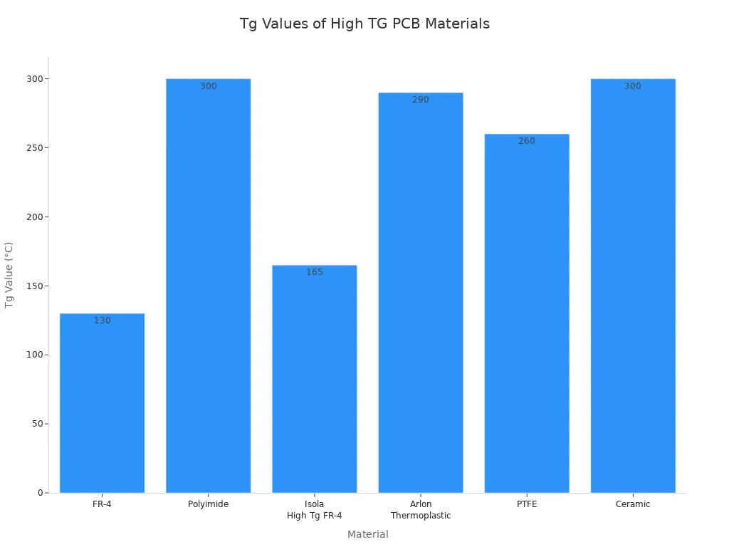
High Tg pcb design uses materials that keep their shape in heat. You protect your circuits by picking the right Tg. High-temperature electronics need higher Tg values than regular boards. You can see the Tg values for common PCB materials in the chart below.
Tip: Always check the Tg value of your PCB material. Make sure it is at least 20–25°C higher than your device's maximum temperature.
Choosing High TG Materials
You have many choices for high-temperature circuit board materials. Each material has its own Tg value and heat properties. Some materials cost more but work better. Others are cheaper but may not last in extreme heat. Look at the table below to compare popular materials.
Material | Tg Value (°C) | Thermal Properties |
|---|---|---|
FR-4 | ~130 | Limited to about 100°C, softens above Tg, not good for high heat. |
Polyimide | >300 | High thermal stability, strong, good for extreme temperatures. |
Isola High Tg FR-4 | 150-180 | Better thermal performance, lower cost than polyimide. |
Arlon Thermoplastic | 290 | Stays strong at high temperatures, budget-friendly. |
PTFE | >260 | Great thermal stability, high dielectric strength, most expensive. |
Ceramic | >300 | Best thermal solution, stays strong up to 1000°C, brittle and costly. |
You can also see a chart comparing Tg values for FR-4, Polyimide, PTFE, and high-tg fr-4.
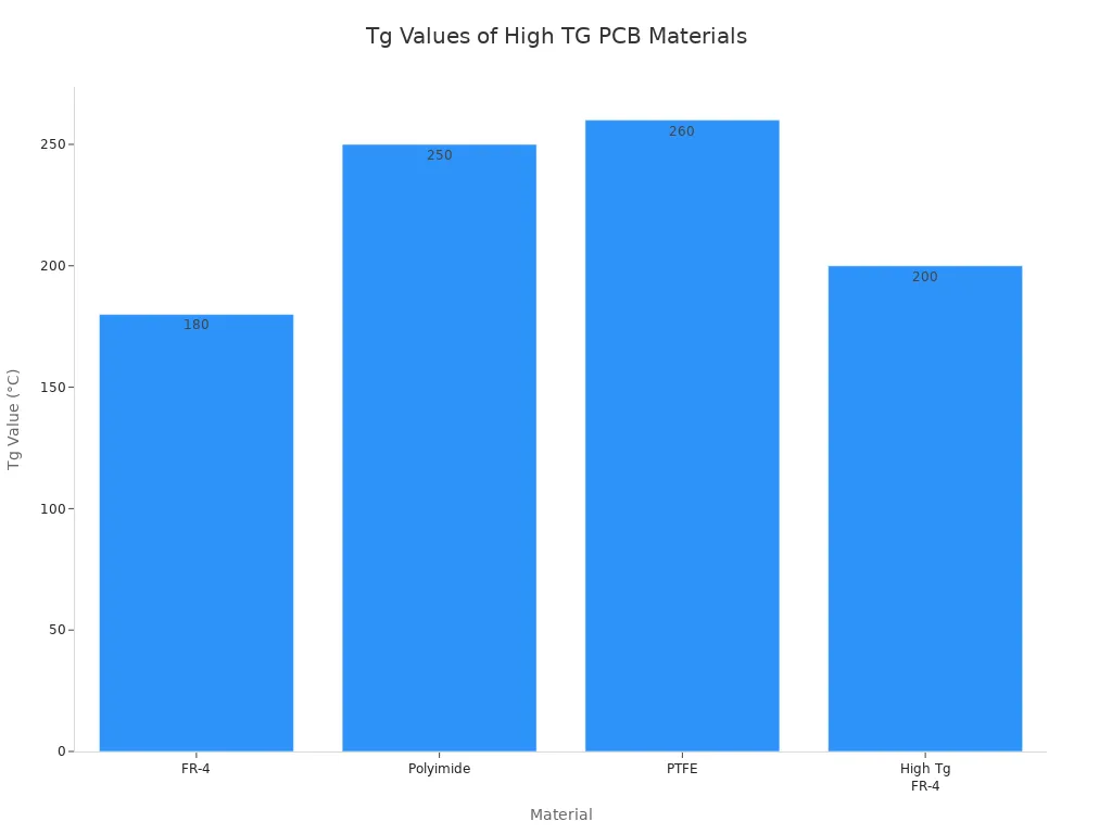
High Tg materials resist heat, moisture, and stress. You get better thermal control, so your board lasts longer. High Tg substrates keep their strength in heat and moisture. This stops warping and delamination. You need these features for multilayer boards and high-density designs.
When you pick a material, think about cost, how easy it is to make, and performance. The table below shows some trade-offs.
Aspect | Description |
|---|---|
Cost | High-Tg materials cost more than standard FR-4 because they use advanced resin and tighter controls. |
Processing | Needs stricter control during lamination and drilling, with smaller temperature windows and careful pressure. |
Moisture Absorption | Some materials still absorb moisture, which can cause problems during soldering if not managed. |
Signal Loss | Some High-Tg materials may not be best for high-frequency signals, which can affect signal quality. |
Note: You must balance performance and cost when picking materials for high-temperature designs. Polyimide and ceramic resist heat best but cost more.
Effects of Heat and Moisture
Heat and moisture can cause big problems for circuit boards. If your board absorbs moisture, it can swell or come apart during soldering. High Tg materials help stop these issues. They keep their strength and do not warp easily. You need this stability for high-temperature electronics.
Thermal challenges can cause warping, cracking, or layers coming apart. High Tg pcb design protects your board from these risks. You must use materials that resist both heat and moisture. High Tg PCBs stay strong even when temperatures change fast.
Alert: Always use high Tg materials for boards that face tough thermal challenges. This keeps your circuits safe and reliable.
You can trust high Tg materials to keep your board stable. They help you avoid expensive repairs and failures. You get better performance and longer life for your devices.
High TG PCB Design Principles
Designing a high tg pcb means you must pay close attention to how you place parts, manage heat, and build your board layers. These choices help your board survive in hot and tough places. You want your electronics to last, so you need to follow smart design rules.
Component Placement
You should start by thinking about where you put each part on your board. Good placement helps your board stay cool and strong. If you group heat-making parts near copper areas or airflow paths, you spread out the heat. This keeps one spot from getting too hot. You also protect sensitive parts by putting them in cooler zones. This helps sensors and chips work better for a long time.
Place hot parts away from each other to stop heat from building up in one spot.
Put temperature-sensitive parts in the coolest areas to keep them safe.
Use larger copper areas as heat spreaders to move heat away from parts.
Space out vias to avoid cracking and stress from heat changes.
Tip: Arrange your parts based on how much heat they make. This simple step can boost your board’s performance and reliability.
Thermal Management
You must control heat if you want your high tg pcb design to work well in high-temperature pcb design. Start by using thermal vias. These small holes move heat from hot parts to the inside or the other side of the board. Choose materials with high thermal conductivity, like metal-core boards, to help spread heat. Thicker copper and wider traces also help move heat away from busy spots.
Use thermal vias to move heat from parts to copper planes.
Pick materials that spread heat well, such as high-tg fr-4 or polyimide.
Add heat sinks or cooling fans for extra cooling in tough jobs.
Place parts to allow good airflow and avoid hot spots.
Use thermal interface materials between chips and heat sinks to lower resistance.
You can also use both passive and active cooling. Passive cooling uses copper planes and heat sinks. Active cooling uses fans or even liquid cooling for very hot boards. Always check your design with thermal simulation tools. These tools show you where heat builds up, so you can fix problems before making the board.
Note: Good thermal management keeps your board safe and helps each part last longer.
Board Stack-Up
How you build your board layers matters a lot. The right stack-up gives your board strength and helps it handle heat. Use polyimide for flexible layers if you need extra heat resistance. For rigid layers, high-tg fr-4 works well. Try to use adhesives that do not break down in heat. Adhesiveless laminates stop layers from coming apart.
Choose copper thickness between 1 oz and 3 oz per square foot for a good balance of strength and current flow.
Keep the number of layers as low as possible to make the board easier to build and less costly.
Make sure the bend radius in flexible areas is at least 10 times the layer’s thickness. This stops cracks.
Reinforce spots where rigid and flexible layers meet. This prevents breaks during vibration or heat cycles.
Match materials with similar expansion rates to avoid stress and warping.
You should always test your board with thermal cycling. This means heating and cooling the board many times to see if it stays strong. This step helps you catch problems before your board goes into real machines.
Alert: Lead-free soldering makes boards harder and less flexible. You need strong materials and smart stack-up to stop cracks and keep your board safe.
When you follow these design principles, you boost component reliability and make sure your high tg pcb design stands up to heat, stress, and time.
Trace Routing and Power/Ground Planes
Trace Width and Spacing
You must pay close attention to trace width and spacing when you design high TG PCBs. Wide traces carry more current and stay cooler. If you use narrow traces, they can overheat and fail. You should always check the current your traces need to handle. Use a PCB trace width calculator to help you pick the right size.
Proper spacing between traces is just as important. Good spacing prevents crosstalk, which can cause signal problems in high-frequency circuits. You also help signals travel cleanly by controlling impedance. This keeps your signals strong and clear. Adequate spacing lets heat escape from traces, so you avoid hot spots.
Space traces to prevent crosstalk and signal loss.
Use enough distance between traces to control impedance.
Allow room for heat to move away from busy traces.
Tip: Always follow the manufacturer’s minimum spacing rules, but increase spacing if you can. This helps your board last longer.
Power Plane Design
You need strong power and ground planes for high-temperature boards. These planes spread current evenly and lower resistance. A solid ground plane also shields your signals from noise. You should keep your power and ground planes as large and continuous as possible.
Stack your board so that power and ground planes sit close together. This setup reduces noise and helps with heat flow. If you split planes, make sure you connect them with plenty of vias. This keeps voltage steady across the board.
Use thick copper for power planes to handle more current.
Place power and ground planes next to each other for better performance.
Connect split planes with many vias to avoid voltage drops.
Note: Good power plane design keeps your board stable and helps all parts work well.
High-Current Paths
You must design high-current paths with care. Wide traces lower resistance and stop heat from building up. Short traces reduce voltage drop and keep signals fast. Place temperature-sensitive parts away from hot spots. Spread out high-power parts to avoid overheating one area.
Use wide traces for high-current paths to reduce heat and resistance.
Keep high-current traces short to lower voltage drop and inductance.
Do not overload power traces. Oversize them to prevent hot spots.
Place sensitive parts in cooler areas of the board.
Alert: If you design high-current paths well, you protect your board from thermal stress and make your electronics last longer.
Tools and Simulation for Reliability
Thermal Analysis Software
You need special software to check if your high TG PCB will work in hot places. These tools help you find hot spots before you make the board. You can test how layout or materials change heat flow. The table below lists some popular software and what they do:
Software Tool | Features |
|---|---|
Cadence Celsius | Multiphysics simulation, PDN analysis, hot spot detection |
SimScale | CFD modeling, ECAD data import, tests conduction, convection, radiation |
Ansys Icepak | Fast design changes, stackup-aware heat maps |
Siemens Simcenter Flotherm | Steady-state solvers, quick thermal management checks |
These tools let you check if your board meets temperature goals. You can fix problems early and save money.
Tip: Always use thermal analysis software before building your board. This step helps you avoid problems later.
PCB Design Tools
You need good PCB design tools to pick the best high TG materials. Altium Designer helps you choose materials and plan for heat. It lets you run thermal simulations for high-temperature boards. You can try different layouts to see which one stays coolest.
Altium Designer helps you pick high TG materials.
It lets you run thermal simulations for better designs.
Simulation Best Practices
You should follow smart steps to keep your board reliable. Start by putting vias under hot parts to move heat away. Use filled or staggered vias to lower thermal resistance. Add copper pours to spread heat. Use finite element analysis to find hot spots.
Pick a high TG material with a Tg at least 20–30°C above your board’s max temperature.
Use thick copper layers to spread heat better.
Place parts to avoid hot spots and keep sensitive areas cool.
When you run many simulations, you can compare designs. Simulation results often match real-world tests. For example, mean cycles before failure in simulation and experiments are very close. This means you can trust your simulation to show how long your board will last in tough places.
You can make strong PCBs for hot places by doing a few things. First, pick materials with high Tg, like Shengyi S1000-2 or ARLON 85N. Next, put parts on the board so heat spreads out and no spot gets too hot. Use things like heat sinks and fans to help cool the board. Keep paths for lots of current short and make traces wide. Simulation tools let you find weak spots before you build the board. For the best results, work with skilled PCB makers and write down what you need clearly.
FAQ
What does "High TG" mean in PCB design?
"High TG" means the board uses materials with a high glass transition temperature. You get better heat resistance. Your board stays strong and does not warp when it gets hot.
Why should you choose high TG materials for hot environments?
You should pick high TG materials because they resist heat and moisture. Your board will not crack or bend easily. This choice helps your electronics last longer in tough places.
Can you use standard FR-4 for high-temperature applications?
You should avoid standard FR-4 for hot jobs. It softens above 130°C. High TG FR-4 or polyimide works better. These materials keep your board safe when temperatures rise.
How do you improve thermal management on a high TG PCB?
You can use thermal vias, thicker copper, and heat sinks. Place hot parts apart. Use simulation tools to find hot spots. These steps help your board stay cool and reliable.
See Also
Enhanced Performance of High TG FR4 PCBs in Extreme Heat
Creating Efficient PCBs Tailored for LED Technology Needs
Key Factors in PCB Production for Challenging Industrial Settings
Top Materials Recommended for Designing High-Speed PCBs
Understanding High-Speed PCBs and Their Unique Characteristics