PCB Reliability Testing: High Temp & Humidity Test
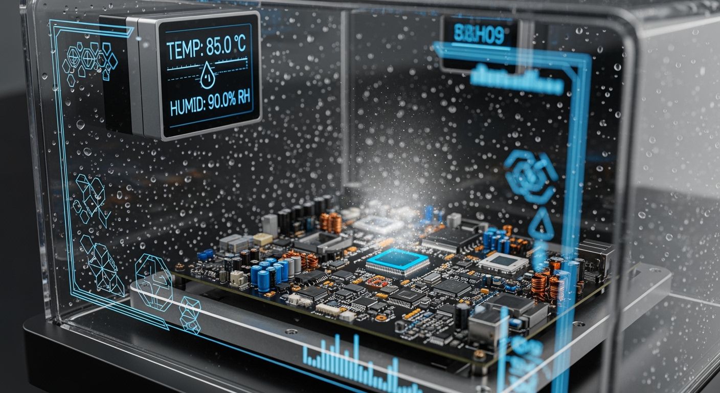
You need to do high temperature and humidity tests. These tests help keep your PCB safe from early problems. If you skip PCB Reliability Testing, you may get solder cracks and corrosion. These issues can cause expensive downtime. Many industries use tests like Temperature Humidity Bias and Highly Accelerated Stress Test. These tests copy tough conditions and help make PCBs last longer.
Test Method | Conditions | Purpose |
|---|---|---|
Temperature Humidity Bias Test (THB) | 85°C, 85% RH, voltage bias | Checks how the PCB works with heat, humidity, and electrical stress. It shows what happens after years in a short time. |
Highly Accelerated Stress Test (HAST) | 130°C, 85% RH, 2.3 atm | Speeds up moisture getting into the PCB. It finds weak spots in PCB encapsulation and solder joints. |
Key Takeaways
Do high temperature and humidity tests to stop solder cracks and corrosion in PCBs.
Use the Temperature Humidity Bias Test (THB) to find moisture problems before using the product.
Pick materials like polyimides that keep out moisture to make PCBs last longer.
Follow good steps in making PCBs to control humidity and keep them strong.
Test often and use protective coatings to help your PCBs last much longer in tough places.
High Temperature and Humidity Risks for PCB Reliability
Why Temperature and Humidity Threaten PCBs
When you use PCBs in places that are hot and humid, you face many problems. These tough conditions can change how your PCB works. They can also make your PCB less reliable. High temperature can bend the board and make it weaker. High humidity lets water get inside the PCB. This can cause hidden electrical problems.
High temperature makes solder joints oxidize and spread out. This can create empty spaces and weak spots.
When the PCB takes in moisture, it can have problems during soldering. The board might swell or come apart.
If the board comes apart inside, copper layers can separate from the base. This makes the board weaker and hurts how it works.
Conductive Anodic Filament can form and make hidden shorts between lines. Humidity and voltage make this happen faster.
Too much water acts like a path for electricity. It can cause short circuits and big bursts of current. This can break parts on the board.
Water from the air can cause rust on open metal parts. This makes it harder for electricity to flow and weakens the PCB.
Tip: You can help your PCB resist humidity by picking materials that do not let water in easily. These materials slow down water getting inside and keep your board safe.
Common Failure Mechanisms (Solder Cracks, Dendrite Growth, Popcorning)
It is important to know the main ways PCBs can fail in harsh places. Many studies show that high temperature and humidity tests can find these problems early.
Failure Mechanism | Description |
|---|---|
Solder Joint Cracking | Cracks at the ends of parts caused by heating and cooling, especially with lead-free solder. |
Copper Trace Damage | Cracks or splits in copper lines from different rates of expansion, often at sharp corners. |
PTH Barrel Cracking | Stresses from different expansions break the connections in plated through-holes. |
High-Temperature Degradation | Heat above Tg bends the board and makes it weaker. |
Internal Delamination | Water getting in separates copper layers from the base or other layers. |
"Popcorning" of Components | Water inside chips turns to steam during soldering, cracking the chip and hurting the part. |
Conductive Anodic Filament (CAF) Formation | Copper moves along glass fiber and epoxy, making hidden shorts when it is wet. |
You often see solder joint cracks where the part legs meet the solder. Heating and cooling causes these cracks, especially with lead-free solder. Popcorning happens when water inside a chip turns to steam during soldering. This makes pressure inside and cracks the chip. Conductive Anodic Filament is a hidden problem. Copper moves along the glass and epoxy, making shorts when there is water and voltage.
High temperatures can change how strong the epoxy is. This makes the board more likely to break.
Keeping water out is important. It stops water from carrying electricity and causing shorts.
Rust can happen from the air, chemical reactions, or rubbing. These things make it harder for electricity to flow and weaken the PCB.
You can use pcb reliability testing like the temperature humidity bias test to find these problems before they stop your board from working. You protect your pcb reliability and how well it works by knowing these risks and using the right humidity tests.
PCB Reliability Testing Methods
Temperature Humidity Bias (THB) Test
The temperature humidity bias test checks how your PCB handles heat and moisture. This test helps you find problems like corrosion and conductive anodic filament. It also finds surface ionic migration. You put your PCB in a chamber with set heat and humidity. You apply voltage while the board faces these tough conditions. This makes aging happen faster and shows hidden risks.
Parameter | Value |
|---|---|
Temperature | 85°C or 110°C |
Humidity | 85% RH |
Duration (Qualification) | 1000 hours |
Duration (Validation) | Up to 2000 hours |
Failure Criteria | Electrical drift or physical failure events |
During this test, you see corrosion of metallisation and dendritic growth. You also see delamination of mould compound. Metallic corrosion and dielectric breakdown can happen. Wire bond interfaces may get weaker. The temperature humidity bias test measures pcb humidity resistance and moisture ingress protection. You can spot solder joint cracking early and make pcb reliability better.
Tip: THB testing helps you find moisture failures before your PCB is used.
Highly Accelerated Stress Test (HAST)
HAST pushes your PCB to extreme limits. This test uses high temperature, humidity, and pressure. HAST makes aging happen much faster. You can see reliability issues quickly. You check moisture resistance, corrosion, insulation breakdown, and delamination.
HAST copies real-world stress. You see how your PCB reacts to tough heat and moisture. You can spot moisture getting inside and package problems. Oxidation and insulation degradation can show up. HAST helps you make sure your PCB will survive harsh conditions.
Corrosion
Insulation breakdown
Delamination
Moisture penetration
You use HAST when you need fast results. You can compare it to THB. HAST finds hidden material defects better. You improve pcb reliability testing and protect your board’s performance.
Other Key Reliability Tests (Thermal Shock, AOI, ET)
There are other important tests for pcb reliability. Thermal shock switches your PCB between hot and cold. This test finds material mismatch and micro-cracks. Electrical reliability testing checks insulation and electrical strength. Thermal cycling simulates repeated heating and cooling. This helps you find fatigue and solder joint cracking.
Thermal Shock Test: Quick temperature changes show material mismatch.
Electrical Reliability Testing: Checks insulation and electrical function with high voltage.
Thermal Cycling Test: Finds fatigue and micro-cracks from heating and cooling.
Insulation Resistance Test: Measures leakage current and dielectric performance.
High Voltage Testing: Uses extra voltage to find breakdown.
Conductive Anodic Filament Testing: Checks for hidden filament growth.
AOI (Automated Optical Inspection) spots visual defects. ET (Electrical Testing) checks for shorts and opens. These tests measure pcb reliability and performance. You see how heat causes loss of electrical strength. Aging tests show how PCB properties change with high temperature. You use these results to make design and manufacturing better.
Note: You should use many tests to cover all risks. This protects your PCB from moisture, heat, and electrical stress.
Testing Method | Effectiveness | Industry Adoption Rate |
|---|---|---|
Stress Testing | Finds hidden defects and weaknesses with tough conditions. | Used a lot for important applications. |
Environmental Stress Screening | Finds early failures by copying real-world conditions. | Used in many industries. |
Burn-in Testing | Finds early failures by stressing parts with high conditions. | Needed in areas with high reliability. |
Vibration Testing | Checks physical strength with mechanical stress. | Important for cars and airplanes. |
These methods help you improve pcb reliability testing. You find problems early and make your PCB last longer in tough places.
Standards and Best Practices for PCB Reliability
Industry Standards (IPC, JEDEC)
You must follow industry standards to keep your pcb safe in tough places. These standards give clear rules for testing and making reliable boards. Groups like IPC and JEDEC set these rules. They help you check how your pcb deals with high temperature and humidity.
Standard | Description |
|---|---|
JEDEC JESD22-A101 | Rules for steady-state temperature humidity bias testing, often used for THB. |
JEDEC JESD22-A110 | Standards for HAST, focusing on fast moisture stress testing. |
IPC-TM-650 | Test methods for checking PCB materials and coatings under humidity and heat. |
IPC-6012 / IPC-6013 | Requirements for strong and flexible printed circuit boards. |
MIL-STD-810 | Military rules for environmental testing, including humidity for tough uses. |
AEC-Q200 | Reliability testing standard for car electronics. |
IEC 60068 | International environmental testing standard (temperature, humidity, vibration, shock, salt spray). |
These standards cover many tests. They help you find problems like solder cracks, moisture damage, and weak spots in your pcb.
Tip: Using these standards lowers the risk of early failures. It helps your pcb pass strict quality checks.
Best Practices for Test Implementation
You should use best practices when you set up pcb reliability testing. Top companies use different tests to check every part of the pcb. They see how the board handles heat, shock, and moisture.
Category | Description |
|---|---|
Thermal Reliability Testing | Checks PCB performance under heat stress, including thermal cycling and thermal shock tests. |
Mechanical Reliability Testing | Looks at the impact of mechanical stresses, including vibration and shock testing. |
Electrical Reliability Testing | Checks insulation and electrical function under high voltage and current. |
Environmental Reliability Testing | Copies harsh conditions to see long-term performance changes. |
You should also follow these steps:
Use IPC-2221 and IPC-6012 for design and making. These help you avoid problems from bending and stress.
Make sure solder joints meet J-STD-001 and IPC-A-610. This lowers the chance of cracks.
Choose IPC Class 3 if you need high reliability, like in medical or aerospace fields.
Test your pcb with both THB and HAST to find hidden defects.
Check for insulation resistance and look for early signs of corrosion.
When you follow these best practices, you make pcb reliability better and lower failure rates. You help your pcb last longer and work better in real-world use.
Prevention Strategies for Reliable PCBs
Material Selection and Design
You can make your pcb last longer by picking good materials and using smart design. Polyimides and Rogers PCBs do not soak up much water. They also handle heat well. These materials help the board stay flat and keep signals clear. Try not to use sharp corners or thin parts. These spots can break more easily. Put vias in safe places to stop water from getting inside. Good conformal coatings keep out water and help with heat. Testing your pcb often helps you find water problems early. This keeps your board strong for a long time.
Pick materials that do not take in much water.
Make boards with round corners and thick lines to stop breaks.
Use conformal coatings to protect against wet air.
Tip: Good materials and smart design help your pcb work well in tough places.
Manufacturing Controls
You can make your pcb stronger by keeping the factory air safe. Good quality starts with steady heat and low water in the air. Many factories use big air systems and filters to keep things clean. Rooms with low humidity and tools that check air all the time help a lot. Drying the board after making it gets rid of water. Putting small packets in the box soaks up water during shipping and storage.
Strategy | Description |
|---|---|
Advanced Moisture Barrier Technologies | Conformal coatings and sealing keep water out. |
Humidity-Controlled Manufacturing Environments | Clean air and checks protect the board. |
Specialized Materials | Materials that do not soak up water keep boards dry. |
Testing your pcb often finds problems from heat and water. You can use computer models to find weak spots before they break.
Protective Coatings and Environmental Management
Special coatings help your pcb last longer in hard places. Silicone works well when things shake or get hot. Polyurethane stands up to chemicals and scratches. It is good for factories. Epoxy makes a hard cover and keeps electricity safe. Parylene is very thin and keeps water out of small parts.
You can also keep your pcb safe by stopping water from getting in during storage and use. Heating the board before building removes water. Baking the board right keeps it safe when soldering. Cards that change color show if the air is too wet.
Note: The right coatings and good air control keep your pcb safe from wet air and help it work better.
You keep your PCB safe from breaking early by testing it in hot and wet conditions. Testing early helps you find problems like dendrite growth and damage over time. You make your PCB stronger by picking tough materials, designing well, and making sure connectors fit tightly. Testing often and keeping things clean protects your PCB. Always test for reliability so your boards work longer.
FAQ
What is the main goal of high temperature and humidity testing?
You want to see if your PCB can survive tough conditions. This test helps you find weak spots before your product fails in the field.
How long does a typical THB test last?
Most THB tests run for 1,000 hours. Some tests go up to 2,000 hours for extra safety.
Which materials help PCBs resist moisture?
You should choose polyimide, Rogers, or FR-4 with low water absorption. These materials keep your PCB dry and strong.
Can you skip reliability testing for simple PCBs?
No, you should always test. Even simple PCBs can fail from heat or moisture. Testing helps you avoid costly repairs.
See Also
Key Factors for PCB Manufacturing in Challenging Environments
Enhanced Performance of High TG FR4 PCBs in Extreme Conditions
Reliable Immersion Tin Finishes for Industrial Control Systems
