Industrial PCB Design that Stands Up to Tough Jobs
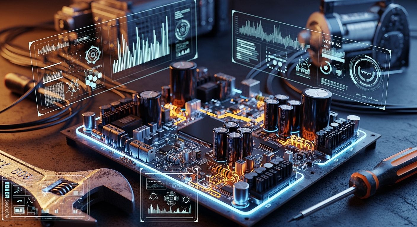
You have hard problems when you design PCBs for tough places. Picking the right material is very important for industrial pcb design. Use industrial-grade ICs with wide temperature ranges to keep boards working from -40°C to 105°C. Ceramic capacitors are good in places with lots of shaking because they handle stress and last longer than electrolytic ones. Pay attention to heat control, shock resistance, and protecting from the environment to make products that work well in rough conditions.
Key Takeaways
Pick materials with high glass transition temperatures. This helps your PCB stay strong in very hot places. - Use industrial-grade parts that work in hot and cold. These parts also resist water and shaking. - Use good thermal management like thermal vias and heat sinks. This stops your PCB from getting too hot. - Put conformal coatings on your PCB to protect it. This keeps out water, dust, and chemicals. It also makes your PCB last longer. - Test your PCB in tough conditions before you use it. This helps you find weak spots in your design.
Harsh Conditions for Industrial PCB Design
Environmental Stress Factors
Designing PCBs for tough places is not easy. Different environments make things harder for your boards. Some common stress factors are temperature changes, humidity, vibration, and chemicals. These can hurt your PCB and make it less reliable.
Here is a table that shows how these stress factors affect PCB reliability:
Environmental Stress Factor | Impact on PCB Reliability |
|---|---|
Temperature Cycling | Can cause cracks and weak solder joints |
Humidity | Raises the chance of corrosion and migration |
Vibration | Can lead to broken parts and failures |
Corrosive Environments | May damage metal traces and cause shorts |
High humidity can make water collect on your PCB. This can cause short circuits and hidden problems. When humidity goes over 70%, the risk of migration goes up. You need to watch these factors if you want your board to last.
Temperature extremes bring more trouble. High heat can make your PCB soft and weak. Cold can make solder joints break easily. Humidity can get inside and cause issues during soldering, like delamination or "popcorning." In tough places, moisture can make hidden shorts between traces.
Outdoor and Industrial Challenges
Outdoor and industrial places add more problems for your PCB. Heat changes can crack solder joints and make the PCB come apart. Water can get in and corrode copper traces. Sunlight can make the PCB brittle and weak over time. Vibration and impacts can break thin boards.
Chemicals are another danger in harsh places. Chemicals in the air or from cleaning can start corrosion and weaken your PCB. Sunlight can change how your board works and hurt the solder mask. Too much light can make your device age faster and not last as long.
Tip: Always test your PCB for these stress factors before using it in tough places. This helps you find weak spots early and fix your design.
You need to know these risks if you want your PCB to last in extreme places. Careful planning and testing will help you make strong products for hard jobs.
Key PCB Design Considerations
Material and Coating Selection
You need to pick the right materials and coatings for industrial pcb design if you want your boards to last in tough places. First, look for materials with a high glass transition temperature (Tg). High Tg materials keep your pcb strong when temperatures change quickly or get very hot. For example, choose a material with a Tg at least 20°C higher than your highest working temperature. This makes your board stronger and more reliable.
It is also important to use materials that do not soak up water. These materials help your industrial control pcb fight humidity and stop swelling or layers coming apart. Chemical resistance is needed too. In places like marine or chemical plants, you need coatings that block strong chemicals and keep your pcb safe.
Tip: Always pick a coating that matches the place where your pcb will be used. Silicone or urethane coatings work well in wet or chemical-filled places. They give good protection from heat and chemicals.
Here is a table to help you compare common coating types for tough industrial pcb design:
Coating Type | Moisture Protection | Chemical Resistance | Notes |
|---|---|---|---|
Acrylic (AR) | Reliable | Lower | Minimal shrinkage during curing |
Epoxy (ER) | Useful | Excellent | Susceptible to water migration |
Silicone (SR) | Good | Moderate | Susceptible to air pollutants |
Urethane (UR) | Excellent | High | Durable and resilient |
Parylene | Exceptional | High | Thinnest effective coating |
You should also check how well your coatings stop electricity from leaking and protect signals. These things keep your pcb safe from shorts and help signals stay clear. Some coatings are easier to fix than others, so think about repairs if you need them.
Component Choices for Reliability
You need to pick parts that can handle tough places. Using industrial-grade parts is the first step for high reliability. These parts work in wide temperature ranges and can handle moisture, shaking, and shocks. Look for parts with wide temperature ratings and strong leads. These things help your industrial control pcb survive stress.
Use high-reliability parts for long life.
Pick parts that resist heat and moisture.
Choose parts with strong leads for better strength.
Check derating to make sure parts are not pushed too hard.
If you ignore part ratings, your board might fail early. Burn-in testing helps you find weak parts before you use your pcb. This test heats up your pcb and finds problems early. Burn-in testing can lower failures in the field by up to 80% in high-reliability jobs.
Note: Always check if your parts work well together and keep signals clear. This step makes sure your industrial pcb design meets rules for electromagnetic compatibility and works well in tough places.
Layout and Thermal Management
A good pcb layout is important for tough jobs. You need to plan your board to handle heat, cut down on electromagnetic noise, and keep signals strong. Start by putting hot parts near the edges. This helps air move and cool your board.
Use thermal vias under hot parts to move heat away.
Make copper thicker to spread heat better.
Add heat sinks to hot parts.
Use thermal pads or sticky glue to move heat.
Line up hot parts with the airflow.
Big copper areas also help. They spread heat across the pcb. For example, a 2 oz copper layer in a high-power industrial control pcb can lower hot spots and make your board last longer.
You should also make traces short and direct. This cuts down on electromagnetic noise and keeps signals clear. Use ground planes to shield and help with electromagnetic compatibility. Thermal tests can help you find hot spots before you build your board.
Vibration and Shock Protection
Tough places often have lots of shaking and shocks. You need to protect your industrial control pcb from these forces. Start with a cover or coating that soaks up shocks and keeps your pcb safe.
Use flexible pcbs to handle stress.
Mount your pcb with rubber or foam to cut vibration.
Put your board in a strong box for extra support.
Add soft pads or rubber rings to stop shaking.
Make strong spots where stress is highest.
Using materials that soak up energy, like viscoelastic polymers, helps control vibration. These materials take in energy and stop it from hurting your pcb. Shock-absorbing mounts or pads also lower the force that hits your board. This helps your industrial pcb design last longer and work better.
Humidity and Corrosion Resistance
Humidity and corrosion can ruin a pcb if you do not plan for them. You need strong protection for your industrial control pcb. Start with a conformal coating. This coating blocks water, dust, and chemicals. Make sure the coating is solid and dry for the best protection.
Use finishes that fight rust, like immersion gold or tin over nickel.
Add silica gel packs to your box to soak up water.
Use boxes with high IP ratings to keep out water and dust.
Keep humidity below 60% with dehumidifiers or climate controls.
Conformal coatings stop rust, shorts, and breakdowns. Different coatings protect in different ways, so pick the one that fits your place. For tough industrial pcb design, urethane and parylene coatings give the best protection from water and chemicals.
Tip: Always use materials and finishes that fight rust for your industrial control pcb. This makes your board last longer and keeps it working in tough places.
By following these key pcb design steps, you make strong electronics that last. You make your boards more reliable, keep signals clear, and help them work better in every industrial control pcb you build. Focus on picking the right materials, good parts, smart layout, and strong protection to master industrial pcb design for tough places.
Reliability Testing and Validation
Environmental Stress Testing
You need to check if your industrial PCB can survive tough places. Environmental stress testing helps you find weak spots before you sell your product. This step is important because it shows how your board acts under real stress.
There are different tests you can use to check your PCB’s strength:
Environmental Stress Screening (ESS): This test changes the temperature and humidity around your board. It helps you find problems that might show up early.
Thermal Cycling: You heat and cool your PCB many times. This test checks if your board can handle fast temperature changes without breaking.
Burn-In Testing: You run your PCB with high heat and power for a long time. This test finds hidden problems that could make your board fail early.
Vibration Testing: You shake your PCB to see if it can handle bumps and shakes in factories.
These tests help you find weak solder joints, loose parts, or cracks. If you skip these steps, your PCB might break when it faces real stress.
You can also use fast life tests to guess how long your PCB will last. These tests push your board very hard for a short time. Here is a table that shows common fast life tests:
Test Type | Description |
|---|---|
Highly Accelerated Life Test (HALT) | Puts the device in extreme conditions to speed up aging and find when it fails. |
Highly Accelerated Stress Testing (HAST) | Pushes the design until it breaks, so you know what needs fixing. |
Burn-In Test | Runs the board for a long time with power to catch early failures. |
Doing these tests helps you make your testing pcb design better and helps your product last longer in hard places.
Tip: Always test your PCB before you send it to customers. Early testing saves time and money by finding problems before they get worse.
Compliance and Industry Standards
You must follow industry rules and get the right certificates to show your PCB is safe and strong. These rules help you meet customer needs and pass safety checks.
Here are some important rules you should know:
Standard | Description |
|---|---|
UL 796 | Checks if printed wiring boards can handle electrical and environmental stress. |
UL 94 | Makes sure plastic parts in PCBs do not catch fire easily. |
IPC-A-600 | Shows how to check PCB quality and puts them in three groups. |
IPC-6012 | Sets rules for strong PCBs, including material and heat limits. |
IPC-A-610 | Gives rules for checking PCB assembly, like solder joints and inspections. |
MIL-PRF-31032 | Makes sure military PCBs are strong and work well in hard jobs. |
You should also know about these certificates:
AS9100D: Needed for aerospace and defense PCBs. It proves your board is safe and strong.
MIL-PRF-31032: Used for military PCBs. It sets tough rules for quality and performance.
ISO 9001: Shows your company uses good quality control.
UL: Proves your PCB is safe and works well.
IPC: Sets rules for making good and strong PCBs.
Following these rules and getting certificates helps you build trust with your customers. It also lowers the chance of failure in important jobs. When you follow these rules, your PCB can handle tough places and keep working for a long time.
Note: Always check which rules and certificates your project needs before you start. This step helps you avoid expensive changes later.
By using strong tests and following industry rules, you make your industrial PCB design safer and stronger. This way, your products can handle the toughest jobs.
Avoiding Common Pitfalls in PCB Design
Frequent Design Mistakes
You can stop many problems if you know common mistakes. These mistakes often make boards fail in tough places. Look out for these issues:
Manufacturing defects, like layers not lining up or bad via plating, can make your board weak.
Burnt parts can happen if you do not leave enough space or if heat builds up.
Moisture can get inside and cause rust or short circuits.
Soldering problems, like cold joints or solder bridges, can make connections unreliable.
Human mistakes during assembly can cause faults that are hard to find later.
Tip: Always check your assembly steps and look over boards closely to catch mistakes early.
Practical Solutions for Tough Jobs
You can use smart ideas to make your PCB stronger and more reliable. The table below shows some choices that help you avoid common mistakes:
Strategy | Description |
|---|---|
Centralize high-vibration components | Put these near mounting spots to lower stress on the board. |
Route critical traces as differential pairs | Use ground shielding to keep signals safe from noise. |
Avoid right-angle bends | Use curved or 45-degree turns to lower strain on traces. |
Isolate noisy sections | Split power and ground planes to keep digital and analog apart. |
Place decoupling capacitors close to IC pins | This helps block noise and voltage spikes. |
You can also:
Use thicker PCB bases, like 2.0mm or 2.4mm FR-4, for more strength.
Try flexible-rigid or pure flex PCBs in places with lots of shaking.
Follow these steps for even better results:
Put mounting spots near heavy parts to lower bending.
Pick shorter parts to limit movement and stress.
Spread out heavy parts so stress does not build up in one spot.
For extra strength, use ceramic circuit boards. They stand up to heat and chemicals well. Keep good records of your steps and tests to meet industry rules. Work with suppliers who track materials from start to finish. Test your boards with both simple and advanced methods. Choose finishes like ENIG, OSP, or silver to help soldering and make your PCB last longer.
Note: Changing your design, like making layouts better or fixing defects, can make signals clearer and help your board last in tough places.
Real-World Industrial PCB Examples
High-Temperature Applications
High-temperature PCBs are used in metal factories, aerospace, and cars. These boards must work in very hot places without breaking. You need to pick materials with a high Tg value. Standard FR-4 has a Tg between 130 and 150 °C. High-temperature PCBs use materials with even higher Tg. This helps the board keep its shape and work right when it gets hot.
Here is a table that shows how high-temperature PCBs are different from standard PCBs:
Feature/Benefit | High-Temperature PCBs | Standard PCBs |
|---|---|---|
Thermal Management | Better at handling heat | Not as good at handling heat |
Mechanical Strength | Stronger and tougher | Regular strength |
Reliability | Works better in tough places | Not as good in tough places |
Current-Carrying Capacity | Can carry more current | Carries less current |
Heat Dissipation | Gets rid of heat faster | Gets rid of heat slower |
Material Properties | Handles heat, chemicals, and stress better | Regular properties |
Applications | Used in metal, aerospace, and car factories | Used for normal jobs |
High-temperature PCBs have many good points:
They do not lose strength or stop working in hot places.
There are fewer short circuits and board problems when it is hot.
Devices last longer because the materials fight heat.
Chemical and Outdoor Exposure
Designing PCBs for chemical plants or outside is hard. Chemicals, water, and sunlight can hurt your board. You need smart ways to keep your PCB safe. Protective coatings block water and dirt. Sealing keeps bad stuff out. Pick materials that last longer in tough places.
You can use conformal coating for a thin shield. Potting covers the whole board for more safety. Urethane coatings are good because they fight strong chemicals and stop rust. These coatings also protect against scratches, bumps, and fast temperature changes. Urethane conformal coatings block water, so you do not get shorts or rust.
Urethane coatings fight strong chemicals and keep your board safe.
These coatings are tough and handle bumps and shocks.
They stop water from causing trouble inside your PCB.
When you use these ways, your industrial PCBs keep working, even in the hardest places.
You can make strong industrial PCBs by using good steps. First, use special testers to find problems. Fishbone diagrams and FMEA help you spot and fix risks. Always ask your partners for safety papers and check their cybersecurity rules. Put parts that shake a lot close to where the board is held. Run sensor traces in pairs with ground shielding for safety. Do not make sharp turns in the traces. These tips help your boards last longer and work better in tough places.
FAQ
What materials work best for industrial PCBs?
You should use high-Tg FR-4, polyimide, or ceramic. These materials handle heat, moisture, and chemicals well. They keep your board strong in tough places.
How do you protect a PCB from vibration?
You can use rubber mounts, thicker boards, or flexible PCBs. These choices help absorb shocks and stop parts from breaking.
Why is conformal coating important?
Conformal coating covers your PCB with a thin layer. This layer blocks water, dust, and chemicals. It helps your board last longer in harsh environments.
How do you test a PCB for reliability?
Run thermal cycling to check heat resistance.
Use vibration tests to find weak spots.
Try burn-in testing to catch early failures.
These tests show if your PCB can survive tough jobs.
See Also
Key Factors for PCB Manufacturing in Extreme Conditions
Crucial Guidelines for High Current Heavy Copper PCB Design
Diverse Industry Applications for Multilayer PCB Technology
