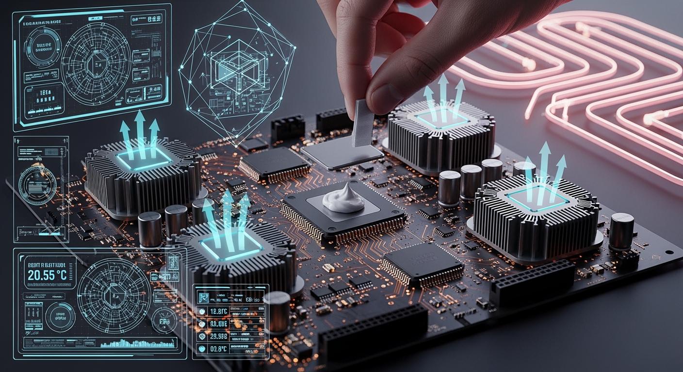
Key Steps to Improve Heat Dissipation in PCB Thermal Design
You can make heat leave your pcb better by using some important steps. These steps help with both the layout and cooling. Good thermal management in your pcb stops it from getting too hot. Too much heat can hurt parts and make your device not last as long. Experts say that good thermal control lowers problems and keeps your pcb working well. Look at this table to see how heat and thermal management change how reliable your pcb is:
Source | Key Findings |
|---|---|
Suntronic | Good heat management is needed for devices to work well and last longer. |
Sierra Assembly | Too much heat can hurt parts and cause problems; good heat control helps things work better and break less. |
Advanced PCB | Thermal management changes how long products last, especially when power gets higher in different uses. |
ALLPCB | Good thermal management lowers returns and fixing costs, so it is very important for things that use a lot of power. |
You should start using these Thermal Design Fundamentals early when you design your pcb. This will help your pcb work better and last longer.
Key Takeaways
Learn about heat transfer modes. Conduction, convection, and radiation help control heat in PCBs. Use thermal vias and heatsinks to move heat better.
Pick materials carefully. Choose materials with low thermal resistance, like copper, to help heat leave the PCB. Thicker copper layers spread heat more easily.
Find hotspots early. Use simulation tools to spot and fix hotspots in your PCB design. This stops damage and keeps the PCB working well.
Place components smartly. Spread out high-power parts to stop heat from building up in one place. Make sure air can flow around these parts for better cooling.
Use good cooling solutions. Add heatsinks, fans, and thermal pads based on how much heat your PCB makes. Plan for active cooling if your PCB uses a lot of power.
Thermal Design Fundamentals
Heat Transfer Modes in PCB
To help heat leave your PCB, you need to know how it moves. There are three main ways heat travels. These are conduction, convection, and radiation. Each way is important for thermal design fundamentals.
Conduction is when heat moves through solid things. In PCB design, heat goes from hot parts into copper traces and layers. Copper spreads heat well because it has high thermal conductivity.
Convection is when heat leaves the PCB and goes into the air. Fans or moving air can help heat leave faster. If the surface is bigger, convection works better.
Radiation is when heat leaves as infrared energy. This way is not as important at normal temperatures. But it can matter if your board gets very hot.
Tip: You can use thermal vias to move heat from the top to inside layers. Heat sinks help pull heat away from parts that use a lot of power. Fans and other active cooling can also help move heat away.
Using these thermal design fundamentals helps you control heat flow. This keeps your PCB cool and safe. Good heat dissipation helps your parts last longer.
Thermal Resistance and Dissipation Paths
Thermal resistance shows how hard it is for heat to move. Lower thermal resistance means heat can move more easily. This is good for your PCB. High thermal resistance can trap heat and make hot spots.
Thermal resistance changes how fast heat moves from hot to cool spots.
Lower thermal resistance spreads heat and stops damage.
Copper has low thermal resistance. FR-4 has high thermal resistance.
You can lower thermal resistance by using thicker copper and more thermal vias.
Material | Specific Thermal Conductivity (W⋅m−1⋅K−1) |
|---|---|
Air | 0.026 |
Aluminium | 205 |
Copper | 401 |
FR-4 | 0.29 (through-plane), 0.81 (across-plane) |
Rogers 92ML | 2.0 (through-plane) |
Gold | 314 |
Silver | 406 |
Solder, SnAgCu | 58 |
Soldermask | 0.2 |
Plating, ENIG | 58 |
TIM, phase change | 2.23 |
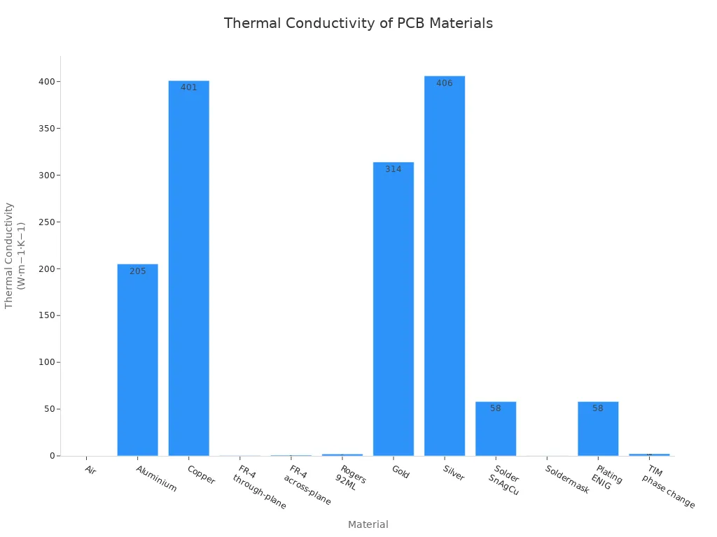
You should pick materials with low thermal resistance for better heat dissipation. For example, copper spreads heat much better than FR-4. Thicker copper lowers thermal resistance and helps heat move. Metal-core and ceramic-filled PCBs also help because they have lower thermal resistance than regular boards.
Industry standards like IPC-2152 and IPC-2221 give you rules for safe PCB design. These rules help you choose the right trace width, thermal vias, and where to put parts to control heat.
If you follow these thermal design fundamentals, your PCB will handle heat better and last longer.
Identifying and Managing Hotspots
Simulation Tools for Thermal Analysis
It is important to find hotspots early in your high power pcb thermal design. Hotspots are spots where heat gathers and can hurt your pcb. You can use simulation tools to help find these spots. These tools show how heat moves and where it builds up before you make your pcb.
Some common simulation tools for thermal simulation for pcbs are:
SPICE simulations check how circuits work.
Field solvers help with hard electromagnetic problems.
S-parameters check signal quality.
DC power integrity analysis keeps voltage steady.
AC power integrity simulations help with high-frequency power.
Advanced field solvers mix thermal, electrical, and mechanical tests.
You can use these tools for different types of analysis:
Signal Integrity Analysis finds problems like reflection and crosstalk.
Thermal Analysis shows where heat goes and finds hotspots.
Power Integrity Analysis keeps voltage levels steady.
Electromagnetic Compatibility (EMC) Analysis checks if your pcb works with other devices.
Simulation testing helps you see where heat goes and find hotspots before you build your pcb. You should always check your simulation results with real hardware tests. This makes sure your high power pcb thermal design works the way you want.
Locating High-Power Components
You need to know where high-power parts are on your pcb. These parts make more heat and can cause hotspots. Use thermal simulation for pcbs to see where heat builds up. Spread high-power parts out on your pcb so one spot does not get too hot.
Here are some ways to manage high-power pcb thermal design:
Spread high-power parts out.
Make sure air can move around these parts.
Use thermal analysis software to find hot spots.
Pick materials that move heat well, like ceramic substrates.
If you do not control hotspots, your pcb can break early. Too much heat can make signals worse and make parts not last as long. Good high power pcb thermal design and thermal simulation for pcbs help your pcb stay safe and last longer.
PCB Layout for Heat Dissipation
Copper Thickness and Layer Stackup
Picking the right copper thickness helps heat leave your pcb. Thicker copper lets heat move away from hot parts faster. For example, if you use 2 oz/ft² copper instead of 1 oz/ft², the temperature rise drops a lot. A power IC can go from 50°C to about 30-35°C. In led pcb design, thick copper spreads heat better and keeps things cool.
A multilayer pcb with big ground and power planes inside helps heat move. You should use at least four layers with 2 oz/ft² copper for led pcb layout. This setup handles more heat and stops overheating. You can also make the copper area bigger around hot parts to spread heat out.
Tip: Connect copper planes to ground or power layers to make thermal zones. These zones lower the hottest spots and help heat leave faster.
Copper Thickness | Layers | Heat Dissipation Efficiency |
|---|---|---|
1 oz/ft² | 2 | Low |
2 oz/ft² | 4 | High |
Component Placement Strategies
You can help heat leave by putting parts in smart places on your led pcb. Spread out hot parts so one spot does not get too hot. Put heat-making parts near airflow or heatsinks. Keep parts that do not like heat, like sensors, away from hot spots.
Group heat sources to control where heat goes.
Use thermal vias under hot parts to move heat to bigger copper areas.
Do not put all hot parts in one place.
Put short parts where air hits first for better cooling.
Use copper pours and heat sinks around hot parts.
You should also use thermal reliefs and vias to help heat move. Good layout of heat holes and channels helps heat leave. In led pcb design, spreading parts out stops too much heat in one place and keeps the board surface even.
Note: Always think about airflow and what your board is made of. Good thermal management stops parts from breaking and makes your product last longer.
Thermal Vias and Dissipation Techniques
Thermal Via Structure and Placement
You can improve heat dissipation in your pcb by using thermal vias. These small, plated holes create a path for heat to move from hot spots to cooler areas. In pcb thermal vias design, you should place these vias directly under heat sources like power devices or LEDs. This helps heat travel quickly to inner copper planes or even to a heat sink.
Thermal vias work best when you use them as part of a larger thermal management plan. Each via has much lower resistance to heat than the FR-4 material in your pcb. If you add more vias, you lower the thermal resistance and help heat escape faster. Engineers often arrange thermal vias in arrays under high-power components. This setup spreads heat and prevents hot spots.
Tip: Use copper or resin-filled vias for better thermal performance. Do not cover thermal vias with solder mask, as this can block heat flow.
Here are some important points for pcb thermal vias design:
Place thermal vias under or near heat-generating parts.
Use a via diameter of about 0.30 mm for good heat transfer.
Keep vias about 0.80 mm apart for best results.
Connect vias to large copper planes to spread heat.
Avoid placing all vias too close together to prevent solder problems.
Evidence Description |
|---|
Thermal vias allow heat to flow vertically through to internal copper planes, acting as heat sinks. |
A thermal via array under a component’s pad increases heat dissipation. |
The combination of thermal vias and copper planes provides a low-resistance path for heat transfer. |
Thermal vias conduct heat from a component’s thermal pad to cooler layers, preventing hotspots. |
Heat transfer through thermal vias occurs via conduction, aided by copper's high thermal conductivity. |
If you design your pcb thermal vias design well, you will see lower temperatures in your pcb prototypes. More vias can improve thermal performance, but after a point, adding more does not help much. Good placement and connection matter most.
Fine Copper in Solder Paste
You can also boost heat dissipation by using fine copper in solder paste. This method adds tiny copper particles to the solder under your components. These particles help move heat from the part to the pcb faster. In pcb thermal vias design, fine copper in solder paste works well with thermal vias and copper planes.
When you use fine copper in solder paste, you create more paths for heat to travel. This lowers the chance of hot spots and helps your pcb last longer. You should use this technique for high-power parts that get very hot.
Fine copper in solder paste improves the contact between the part and the pcb.
It works best when combined with thermal vias and large copper areas.
This method helps in led boards and power electronics where heat is a big problem.
Note: Always check your pcb design with thermal analysis tools to see how well your heat dissipation methods work.
By using both pcb thermal vias design and fine copper in solder paste, you can make your pcb handle heat much better. This keeps your board safe and helps your products work longer.
Thermal Management in PCB Design
Heatsinks and Thermal Pads
You can make your pcb cooler by picking the right heatsink and thermal pad. Heatsinks take heat away from hot parts and spread it out. It is smart to think about pcb heatsink selection early. How you attach the heatsink matters for how long it lasts. Good attachment keeps the heatsink steady and helps heat leave. You can use thermal tape or push pins. Each way works for different power needs.
Thermal pads and thermal paste fill spaces between the heatsink and the part. This helps heat move better. Look at the table to see how they are different:
Type | Advantages | Disadvantages |
|---|---|---|
Thermal Pads | Easy to use, clean, same thickness, strong, can use again | Lower thermal conductivity (1-6 W/mK), not as good for strong heat parts |
Thermal Paste | Higher thermal conductivity (4-12 W/mK), good for rough surfaces | Messy, needs careful spreading, can dry out |
You can use thermal pads in many places like custom pcb designs, LED lights, and laptops. For pcb heatsink selection, match the pad thickness to the space. Use 0.5mm to 1mm pads for small spaces and 1.5mm to 2mm for bigger spaces.
Tip: Always check that the heatsink sits flat on the part. This helps heat leave and keeps your pcb safe.
Cooling Solutions for High-Power Applications
You need strong cooling for high power uses. Thermal management in pcb design uses many ways. You can use thicker copper traces, metal-core pcbs, or add a heatsink. For more cooling, you can use fans, heat pipes, or liquid cooling.
Cooling Method | Efficiency Description | Cost and Complexity Description |
|---|---|---|
Thicker Copper Traces | Lowers resistance and spreads heat well. | Cheap, easy. |
Works as a heatsink, moves heat fast. | Medium cost, makes board stronger. | |
Cooling Fans | Moves air, keeps temperature steady. | Cheap, makes board bigger and uses more power. |
Heat Pipes | Moves heat well, good for small devices. | Medium cost, needs careful planning. |
Liquid Cooling | Removes lots of heat, best for high power uses. | Expensive, hard to build. |
Forced Air Cooling | Lowers temperature by 20-30°C, good for medium heat. | Cheap, can be loud and bigger. |
You can lower part temperatures by 15–25°C with forced air cooling. Fans use 1W to 10W of power. Passive cooling works for low heat, but active cooling is better for high power uses. Advanced cooling costs more because of special materials and tricky builds. Most of the cost comes from materials and extra things like thermal vias.
You should always plan thermal management in pcb design for your needs. Good pcb heatsink selection and cooling keep your board safe and working well.
You can make your PCB work better by using good heat control steps.
Pick the best board materials and parts for your project.
Think about where your PCB will be used and use cooling methods.
Find parts that get very hot, pick heatsinks, plan how to attach them, add thermal vias and copper planes, and test your board.
Keep checking your design with new simulation tools. This helps you find heat problems early and fix them. You can stop mistakes like using thin traces, bad thermal via plans, or not thinking about airflow. Change your design if you need to so your PCB stays safe.
Always put thermal management first in every PCB project. This keeps your board cool and makes your products last longer.
FAQ
What is the best way to cool a PCB?
You can use heatsinks, fans, or thermal pads. Thick copper and thermal vias also help. Choose the method based on how much heat your board makes.
How do thermal vias help with heat?
Thermal vias create a path for heat to move from hot parts to cooler layers. You place them under power devices to lower temperature and prevent damage.
Can you use regular solder paste for heat dissipation?
Regular solder paste does not move heat well. Fine copper in solder paste improves heat transfer. Use it for high-power parts to keep your PCB safe.
Why does component placement matter for heat?
You spread hot parts out to stop one area from getting too hot. Place heat-sensitive parts away from heat sources. Good placement keeps your board cool.
See Also
The Superior Heat Management of Ceramic Printed Circuit Boards
Key Guidelines for Crafting Heavy Copper PCBs for High Currents
Investigating Thermal and Electrical Performance of Aluminum PCBs
7 Vital Quality Assurance Steps for Heavy Copper PCB Assembly
Frequent Challenges and Solutions in PCB Design for SMT Needs