PCB Stator vs. Conventional Copper Winding
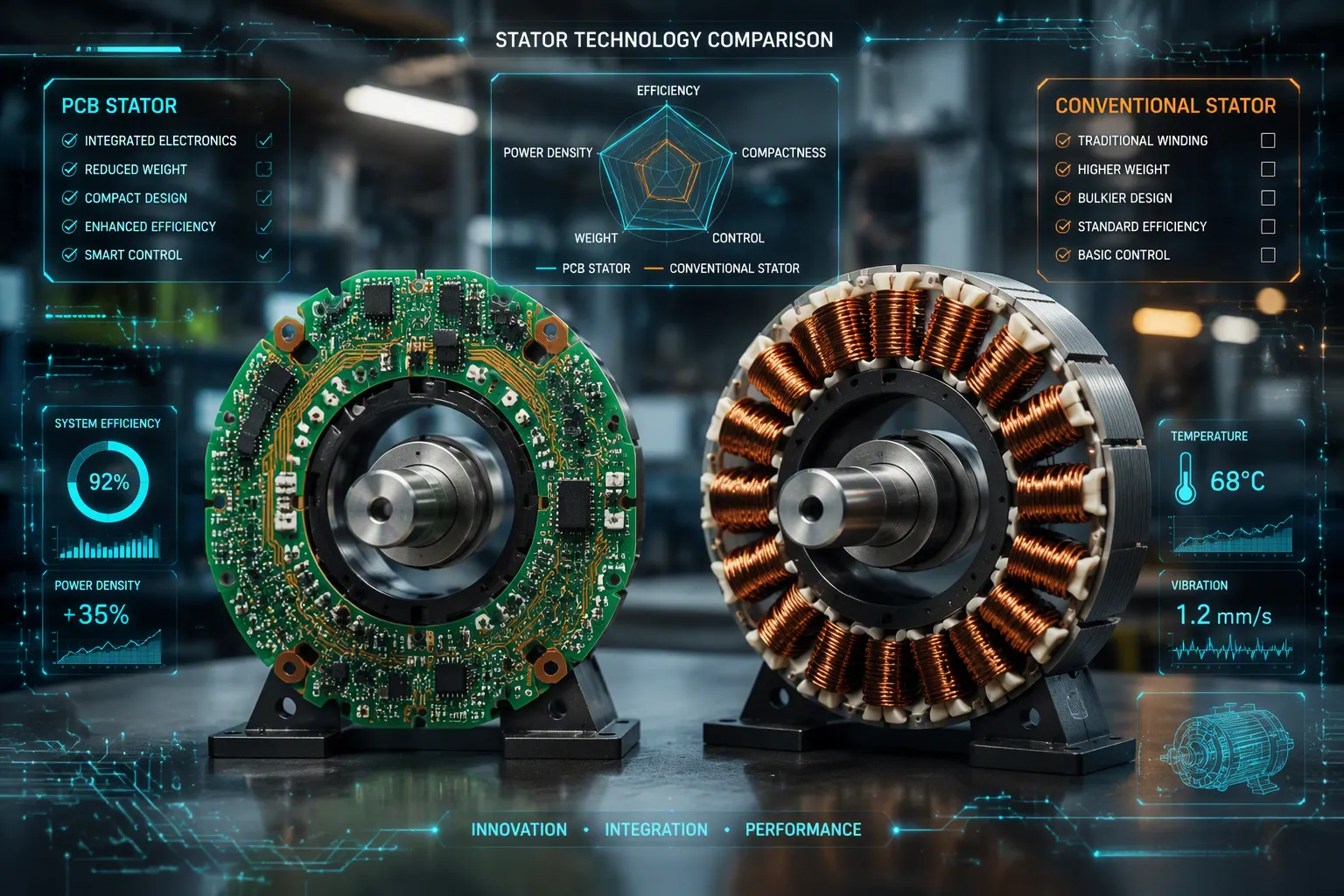
PCB Stators work best in small, high-frequency, precise uses. Regular copper windings are still the practical pick for high-current, budget-friendly designs. Think about a light axial flux fan motor. A PCB Stator swaps bulky copper coils for thin copper traces on a circuit board. This design lowers weight and thickness before anyone even looks at costs.
The choice comes down to several points. Engineers compare efficiency, heat performance, power density, building complexity, cost, and dependability. Each factor tips the balance between these two electric motor designs. A small fan motor leans toward printed windings. A large industrial drive often leans toward copper. The right answer comes from the use case, not from one single rule for all.
Key Takeaways
PCB stators are thin and light, which makes them great for small devices like drones and fans.
Copper windings can handle a lot of power and cost less for big jobs like electric cars.
PCB stators work with little noise and use energy well, especially when they spin fast.
Copper windings are dependable and well-tested for hard industrial work.
Pick what fits your needs: size, weight, power, and budget.
What Is a PCB Stator?
From Copper Windings to Printed Circuit Boards
A PCB stator is a motor winding made of conductive traces on a very thin printed circuit board. These traces take the place of the large coils seen in regular motors. This design makes motors smaller, lighter, and flat. A printed circuit board with conductive paths carries the current that once flowed through thick wire bundles.
In the past, engineers wound copper wire around iron teeth by hand or machine. That method created a heavy, 3D coil setup. A PCB stator flattens the same electrical job into a thin sheet of laminate. The conductive traces rest on an insulating base instead of a steel core. This change removes the iron core and its related energy losses.
Benefits of a Coreless Axial Flux Design
The PCB stator is often used in an axial flux motor, also known as a disc motor. In this design, a coreless stator with PCB armature windings sits between two magnet rotors. The magnetic flux moves parallel to the shaft's axis. This setup creates a compact, pancake-shaped motor.
A coreless design gets rid of iron losses and cogging torque. The rotor spins with less drag and smoother movement. PCB stator technology also shortens the magnetic path, which boosts torque per unit volume in many small motors. These features work well for custom PCB stator motors in fans, drones, and compact servos. A printed circuit board stator gives these benefits without the weight of a laminated steel core.
What Is Conventional Copper Winding?
Wire-Wound Stator Construction
A normal copper wound stator makes its magnetic field from real wire coils. Makers wrap enameled copper wire around steel teeth that are stacked in layers. The wire sits inside slots cut into the stator core. This setup creates a strong magnetic circuit that holds a lot of copper.
Insulation is very important in this design. Slot liners made from heat-resistant plastic films, like polyimide, move heat from the windings to the stator core. Special tapes and blocking felts form insulation with no gaps after they cure. These materials remove air pockets and keep the coil shape in place. Epoxy glues with aluminum oxide or boron nitride powder boost heat transfer to about 1.5 to 3.0 W/mK. Vacuum treatment removes air pockets that would block heat flow.
Fill Factor, Cost, and Reliability
Fill factor shows how much copper fits inside a slot. A copper wound stator packs wire tightly, so it can carry more current per volume than a printed board allows. This density gives normal copper wound motors an edge in high-torque, high-current jobs.
Copper price shapes the money side of these designs. In 2024, bulk orders of 500 kg for basic ETP copper wire, Class 130, 18–22 AWG, cost between $6.99 and $9.99 per kg. Smaller B2B orders run $8.20 to $11.20 per kg. Retail spools cost $10.35 to $17.08 per kg. These numbers show that copper wound stators rely on a stable supply chain with easy-to-guess material costs.
Reliability comes from years of real-world use. Copper wound motors handle high heat, shaking, and overloads. Makers understand how these motors fail. This track record makes normal copper wound machines a safe choice for tough factory jobs.
PCB Stator Motors vs. Copper Windings
PCB Stator Motor Efficiency and Power Density
Losses decide the winner in any efficiency contest. A pcb stator moves current through flat conductive traces instead of round wire. At high frequencies, current crowds toward the conductor surface, a behavior called the skin effect. Flat traces spread that current across a wider face, which lowers the penalty. Proximity effect follows the same pattern. Nearby conductors push current into uneven paths, and thin traces limit that distortion. Iron losses vanish in a coreless axial flux design because no steel core remains to heat up and waste energy.
These advantages give pcb stator motors strong efficiency at high switching frequencies. A pcb based stator also packs its windings into a thin disc, so power density rises in a small package. Conventional copper-wound counterparts still win on raw torque per volume. Their dense wire bundles carry more current in the same space. Engineers who need high torque from a small frame often accept the extra losses to get that current capacity.
Thermal Cooling and Current Limits
Heat removal separates these two designs as much as loss generation does. A pcb stator exposes a large surface area relative to its volume. That ratio helps heat escape through the laminate and into the surrounding air. A copper wound stator hides its heat inside slot liners and steel teeth, so heat must travel a longer path to reach the frame.
The insulation material in a printed board limits the other side of the thermal equation. Laminate holds less copper per unit volume than a wound slot, so fill factor drops. Lower fill factor means less copper to carry current and more resistance per amp. Continuous current stays limited without active thermal management. Designers who push a pcb stator into high-power-density territory must add cooling beyond natural convection.
One advanced approach builds integrated internal liquid-cooling paths directly into the stator structure. Instead of bolting on an external cooling jacket, the channels sit close to the winding heat source. This placement removes heat where it starts. A representative multilayer PCB winding stack has been fabricated and tested in a controlled liquid-cooling setup to evaluate winding-temperature behavior under electrical loading. Such active cooling enables higher power density and reduced mass for electric motors in aviation and advanced mobility applications.
Copper wound stators handle overloads with more forgiveness. Their thermal mass absorbs short bursts of excess current. A conventional copper wound machine also benefits from decades of proven insulation systems. Engineers know how these motors fail and how to predict their limits. A pcb stator demands tighter thermal design, but it rewards that effort with a thinner, lighter motor when active cooling is available.
Manufacturing and Cost Trade-Offs
PCB Stator Technology in Production
A PCB stator uses copper lines on a circuit board instead of wire coils. This removes the need for hand winding from the production line. Automated PCB making takes care of the rest. Machines drill, plate, and etch with high repeatability. Each board matches the last one within tight errors. This accuracy helps in high-frequency designs where small winding changes hurt performance.
Tooling cost stays low for a PCB stator motor. Makers use existing PCB fabrication methods instead of building custom winding machines. After prototyping, serial production scales up with limited capital outlay. ECM's PCB Stator technology, paired with flexible assembly operations, cuts manufacturing capital investments by allowing standardized hardware packages across SKUs. This approach removes variations in winding programs and excess work-in-progress management, which lowers overhead.
After prototyping, serial production of PCB stator motors can be scaled up with limited capital investment.
A normal BLDC motor needs special stamping and winding equipment. Estimated tooling cost is high, often about two times that of a PCB stator motor. The new approach offers lower capital cost and faster time to market by greatly cutting production complexity and prototyping time.
Copper Winding Process and Cost at Scale
Regular copper winding benefits from mature supply chains. Raw copper wire is still widely available at predictable prices. Makers have improved the winding process over decades. Automated flyers and needle winders handle high volumes with proven scalability. These machines pack wire tightly into slots, which raises fill factor and current capacity.
Several manufacturers offer design and production services for OEM clients. ECM PCB Stator Tech runs an Industrial OEM Products Division. This division provides engineering, software design, and client services for large electric motor equipment makers. The team supports electric motor development on PrintStator Motor CAD. It also advises on modeling, prototyping, production, and commercialization of products that use PCB Stator technology.
Manufacturer | Division | Services for OEM Clients |
|---|---|---|
ECM PCB Stator Tech | Industrial OEM Products Division | Engineering, software design, and client services for large electric motor equipment manufacturers; electric motor development on PrintStator Motor CAD; advisory for modeling, prototyping, production, and commercialization of products incorporating PCB Stator technology |
"ECM is working with large electric motor OEMs in developing new products and applications with PrintStator Motor CAD and PCB Stator innovation. With Lisowsky and this new division, we're providing a dedicated team to serving this demand and on-boarding additional motor OEMs who can leverage the technology," says ECM CEO Brian Casey.
Partners include L3 Harris, Celestica, B. Hepworth, and East West Manufacturing. These ties show that PCB stator technology has moved beyond the lab. Copper winding still wins on material cost and supply chain depth. A PCB stator wins on automation and design flexibility.
Application Suitability for PCB Stator Motors
Where Printed Circuit Board Stator Motors Excel
Small drone propulsion shows what pcb stator technology can do. One prototype measured 16 x 17 x 5 mm and weighed only 1.5 grams. These small dimensions let a coreless design fit right into the circuit board. The device still turned a small propeller. This method allows much smaller, cheaper units for compact aircraft.
The designer wanted a small, low-cost drone. Brushed DC units would not fit in the space available. PCB-based motors fixed that problem with their thin shape and light weight. The coreless design got rid of the iron core completely. Testing proved it could make useful thrust within those tight size limits.
Noise reduction gives pcb stator motors another edge. These units run quiet and offer good efficiency. The winding sits fully sealed in FR-4 material. This build greatly cuts vibration because fewer moving parts exist. Infinitum's air-core motor series shows these benefits in HVAC fan applications. The heavy-duty variant cuts energy, emissions, noise, and waste all at once.
Compact servos and axial flux fan units also gain from a PCB-based design. The thin profile fits inside tight enclosures. The large surface area helps heat escape without active cooling. These traits matter most when space and weight top the requirements list.
Where Copper-Wound Stators Remain Strong
EV traction units need high current capacity that copper windings provide. A dense wire bundle carries more current per volume than any circuit board trace. Per-unit cost also stays lower at high production volumes. Large industrial drives follow the same logic. These applications need torque density above all else. Wound designs provide that density with decades of proven reliability.
The supply chain for copper wire is mature and predictable. Manufacturers understand how these units behave under extreme loads. Heat, vibration, and overload conditions cause predictable failure modes. Engineers can design around those limits with confidence. The manufacturing process scales to high volumes without custom tooling changes for each motor design.
The choice between pcb stator motors and wound units depends on priorities. Small fans, drone units, and compact servos favor the thin, quiet pcb stator design. EV traction and industrial drives favor the high-current winding approach. Each technology serves its intended applications within the broader landscape of electric motors. Engineers must evaluate their specific power level, volume, and thermal constraints.
Decision Guide: PCB Stator vs. Conventional Copper Winding
When to Choose a PCB Stator
A design team should pick a pcb stator when the motor itself is a key part of the design. This means things like efficiency, shape, weight, noise, and control matter. A pump or fan system being built or fully redesigned lets engineers use the thin and light printed board winding. Supply chain safety is another reason. A pcb stator uses standard circuit board making, not special winding tools, so sourcing stays easy.
Precision and quiet operation push the choice further toward printed windings. Slotless designs have no iron teeth, which lowers cogging torque, vibration, and position error. Near-silent operation fits medical devices, office gear, and home HVAC. Weight and size savings add more reasons. Test results show up to 70% less weight and up to 50% less size at the same power. Efficiency goes over 90% and up to 95% in some uses. A pcb stator motor also lets drive and control electronics go right on the board, which shortens wires and makes assembly simpler.
Thermal design needs thought before deciding. Spread-out windings plus thermal vias and heatsinking inside the PCB move heat away from the wires. A team that needs a quick prototype should think about this option. Time to prototype matters when a project cannot wait for custom tooling.
When to Choose Conventional Copper Winding
A copper wound stator stays the better choice when the motor shape is set and cannot change. Retrofits into old housings leave no room for a flat disc winding. Cost also drives the pick. When cost is the only thing that matters and a standard induction motor meets the need, a copper wound machine wins on price and availability.
Production volume shapes the costs. Very low volume rarely makes sense for co-development investment, because the return will not come in time. High volume programs benefit from mature supply chains and proven scale. A copper wound stator also focuses flux better through its iron teeth, which raises power density and thrust per unit volume. Iron laminations give heat a clear path out of the winding, so continuous power stays higher without extra cooling gear.
The table below shows the differences.
Decision criterion | PCB stator | Conventional copper winding |
|---|---|---|
Cogging torque and vibration | Slotless design removes iron teeth | Slotted design creates periodic pull |
Power density | Lower without flux focus | Higher through flux focus |
Thermal path | Limited by laminate insulation | Direct through iron laminations |
Best fit | Precision, low noise, weight-critical | High current, fixed shape, cost-driven |
Engineers who weigh these points against their own power, size, and heat limits will pick the right technology for the job.
PCB stator technology gives you a smaller, lighter, high-precision motor with good heat-releasing surface area. Regular copper winding gives you a higher fill factor, proven manufacturing, and lower cost at high volumes. Each design meets different needs.
Engineers should pick a PCB stator when shape, automation, and low inertia matter more than raw current capacity. They should pick regular copper winding when current handling, supply chain maturity, and cost drive the design. PCB stator motors are great in compact, quiet applications. Wound designs lead in high-current industrial work. The best choice depends on power level, volume, and thermal limits. No single number decides the winner for all electric motors.
FAQ
What reduces noise in a PCB stator design?
The slotless build takes away iron teeth and cogging torque. Vibration drops a lot. This design works well for quiet motor uses like medical equipment.
How does current capacity compare between these electric motors?
The printed circuit board stator has a lower fill factor, which limits continuous current. A copper wound design fits more wire and handles overloads better.
Which option offers faster prototyping?
This technology uses standard circuit board manufacturing. It removes the need for custom winding tools. Prototyping gets faster and cheaper. Conventional winding needs special equipment.
See Also
Panasonic Copper-Clad Laminates Used In PCB Fabrication Processes
A Guide To Heavy Copper Multilayer PCB Production
Horizontal Copper Sinking Technology In PCB Production Applications
