PCB Stators for Robotics and Robotic Actuators
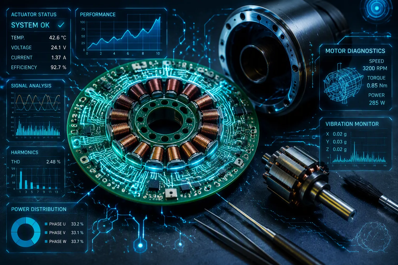
PCB stators are circuit boards with many layers. Their copper lines replace wire coils in axial-flux brushless motors. For robotics, this new idea is very important. These stators are very thin, with a compact profile. They create no cogging torque, which is key for smooth motion in many robot applications. Designers put Hall-effect sensors right on the board.
Older designs make robot joints less compact and harder to put together. PCB stator technology leads to a smaller, lighter, and more precise actuator. This technology cuts the length by 50 percent and weight by 50 percent compared to wire-wound types. Learning about PCB stator technology changes robotics engineering for new direct-drive and collaborative robots.
Key Takeaways
PCB stators use copper traces on circuit boards instead of wire coils, which makes motors thinner and lighter.
They get rid of cogging torque, which gives smooth motion for safe human-robot interaction.
Sensors built into the stator board make assembly easier and cut down on wiring.
Low-inductance designs need high-frequency PWM drives to control them precisely.
Use PCB stators to reduce weight by half and length by half in robotic joints.
How PCB Stators Work
Electromagnetic Principles and Layer Stacking
PCB stators use axial-flux ideas. The magnetic flux moves along the rotor axis. This lets the design be a thin disc. Engineers stack many PCB layers to make concentrated windings. Each copper trace becomes a fractional-slot coil.
Stacking layers directly increases the number of winding turns. For example, one layer had only about 10 spiral turns per coil. That was not enough magnetic flux. By stacking four layers and connecting them, the turns became 40 per coil. That was enough to move the rotor.
Even more layers are used in advanced designs. One module has four 12-layer HDI modules, making 48 layers total. The stator has a resistance of 4.70 ohms and inductance of 3 mH. Its torque constant is 32.0 mNm/A. Continuous stall torque is 23.4 mNm. The simulated back-EMF at 3000 rpm is 9.97 V peak, and measured is about 9.48 V peak. Copper-etched conductors replace wire windings completely. This PCB stator technology cuts out manual winding and gives the same performance in every unit.
Commutation Methods for PCB Stators
Engineers use two main ways to control these motors. Six-step trapezoidal commutation is for simple speed control. Field-oriented control (FOC) is better for robotics. FOC gives smooth torque. That smoothness is key for robot joint actuators that need precise motion.
The low inductance of stator coils needs careful handling. These motors need higher switching speeds than normal brushless motors. Standard motor controllers use 20-30 kHz PWM frequencies. That is not enough for low inductance motors. At 20 kHz with 5 A continuous current, current ripple is ±0.6 A. At 100 kHz, the ripple drops to one-fifth of that. For a 24 V bus motor, 100 kHz PWM is needed to get about 10% current ripple. AC loss from rotor-field harmonics and switching frequency also affects efficiency. Higher switching frequencies lower the electrical time constant. This allows faster current response.
The benefit is more precise motor control for robots that need quick torque changes. Engineers must choose drive electronics that work at these higher frequencies. The trade-off is worth it for the smooth, responsive control that robotic actuators need.
PCB Stator Technology for Robotic Joint Actuators
Key Advantages Over Wound Stators
PCB stator motors give clear gains over regular wire-wound designs. They make zero cogging torque, weigh half as much, and are half as long. These differences matter in robotics, where every millimeter and gram counts. A straight torque-current link holds across the whole operating range. This straightness is key for sensorless force control in collaborative robots. Engineers can figure out torque right from current without a torque sensor.
ECM has built its PCB stator technology into small, strong actuator assemblies for robotic joint uses. This directly helps direct-drive actuation in robotic joints. The axial flux shape allows small, space-saving integration. Direct drive with zero cogging gives smooth, quiet, high-precision motion. Low EMI plus an integrated drive leads to cleaner signals and less system noise. A delta robot run by three 2Nm servo evaluation motors with integrated control and absolute encoders shows these features for real-time multi-axis coordination.
The performance gains also reach power density and efficiency. PCB stator motors get up to 70% weight reduction and 50% size reduction versus regular motors of equal power. Efficiency goes past 90% across a wide operating range and hits up to 95% in targeted uses. Sound performance is near-zero thanks to the slotless design. These advantages make PCB stators appealing for robotic uses that need high torque density in tight spaces.
Technical Criterion | Performance Benefit |
|---|---|
Compact dimensions & torque responsiveness | Enables natural and safer human-robot interaction |
Power density | Up to 70% weight reduction and 50% size reduction vs. conventional motors of equivalent power |
Efficiency | Exceeds 90% across broad operating range; up to 95% in targeted applications |
Acoustic performance | Near-zero acoustic signature due to slotless design (no cogging torque) |
Thermal management | Distributed windings across PCB substrate provide large heat dissipation surface area |
Integrated Feedback and Thermal Performance
The flat PCB shape lets hall sensors, encoders, and temperature sensors go right onto the stator board itself. This integration makes assembly simpler and cuts wiring. ECM's "Eight Ball" servo motor shows this approach. It pairs a 50:1 harmonic drive with a PCB stator motor and dual encoder feedback. This setup gets 33.9 Nm peak torque and 18.8 Nm continuous torque while weighing only 0.57 kg with dimensions of 2.95″ × 3.35″ × 1.96″. The 25 mm and 38 mm motors use PCB termination on the stator. This cuts the space needed for normal lead connections and makes electrical integration into a customer's product simpler.
Thermal performance gains come from the copper traces and axial-flux topology. ECM motors are cooled by patented thermal features that pull heat from the stator to the case for release to ambient. The active area of ECM's stators is the area between the inner and outer via rings. Copper traces outside the outer end turns are not active. They work as heat pipes to carry heat from the center of the stator to the outside edge. There, the case grabs the heat and releases it to ambient. These stator heat pipes also work in the Z direction to spread heat to the top and bottom layers of the board. The power range for PCB stator motors changes a lot by design. ECM's current technological readiness allows for solutions from 4W to 20kW. Peak current handling is lower than thick wire, but the distributed windings give a large heat dissipation surface area.
Design Challenges for PCB Stators
Material Selection and Thermal Limits
Engineers have to make hard choices when they pick materials for pcb stator designs. Copper thickness is a big decision, with various standard options available. Thicker copper means less resistance and more current it can handle. But thicker copper makes it harder to print fine traces and harder to etch. Core materials are another choice. Soft magnetic composites have low eddy current losses and are easy to shape. Laminated steel has higher permeability but weighs more and limits the shape. The board stack-up also matters. More layers mean more winding turns and more torque. But each layer you add raises cost and thermal resistance.
Thermal limits come from the thin traces. Continuous current density is limited by thermal constraints and depends on how well the motor is cooled. A design with poor airflow can only sustain lower current densities, while forced convection or a heat sink allows higher values. Engineers must balance current density against temperature rise. Too much heat damages the board substrate and shortens motor life.
Torque Ripple and Drive Electronics
Zero cogging torque does not mean zero torque ripple. According to Allient's motor technology guide, ripple can come from current, not just cogging. This kind of ripple happens when the controller's current profile does not match the motor's real torque output at each rotor angle. Every motor design has a nonlinear torque-versus-angle relationship. This comes from pole count, slot count, skew, and saturation. A mismatch between commanded current and real torque creates ripple. Wrong commutation angle settings also cause torque ripple. This is a setup issue common to all motor-drive combinations.
Several sources add to torque ripple in pcb stators:
Commutation discontinuities — six-step commutation makes torque steps and is often the biggest single cause of vibration and noise.
Poor current loop tracking — distorted or lagging current makes distorted torque and more ripple, especially at higher speeds.
Cogging torque — caused by magnet and stator slot interaction; zero cogging removes this cause, but other causes remain.
Mechanical resonance amplification — small torque changes can excite system resonances and become big vibrations through flexible linkages, belts, gears, or lightly damped structures.
Sampling, PWM, and timing effects — discrete control adds ripple, and loop timing and PWM frequency both matter.
Drive electronics must meet special demands. Low-inductance motors need faster PWM switching, usually 50 to 100 kHz. Current sensors must have low latency for accurate control. These needs raise the cost and complexity of the drive system.
Cost also shapes pcb stator design decisions. Traditional copper wound stators need special winding machines that are costly and complex. Retooling is often needed when you make two separate stator types. In contrast, PCB stators are made using the mature, globally available PCB manufacturing industry. Multiple stator configurations can be printed at the same time on the same machine. This makes prototyping and scaled production easier, cheaper, and faster.
Motor Type | Estimated Tooling Investment | Reason |
|---|---|---|
Custom ECM PCB Stator Motor | Low | Leverages existing PCB manufacturing practices |
Custom BLDC Motor (traditional wound stator) | High | Typically around 2x a PCB stator motor due to specialized stamping and winding equipment required |
For robotics engineers, these trade-offs are manageable. Multi-layer boards and better thermal materials keep closing the gap. The benefits of pcb stator technology — zero cogging, low weight, and integrated sensing — often outweigh the remaining challenges.
Robotic Joint Actuator Applications and Trends
Use for Robotic Joint Actuator Systems
ECM and Cone Drive have embedded pcb stators into robotic joint actuator modules. These compact, customizable units deliver high torque density. The result is small but powerful actuator packages that fit directly into robot joints. Engineers use these in direct-drive robot arms at shoulder and elbow joints. Exoskeletons for hip and knee assistance also rely on this technology. Cobots benefit from collision-safe haptic interaction. Mobile robots use wheel hub motors built on the same principle.
A fully integrated actuator gear drive platform combines an integrated harmonic drive with a hollow-shaft robotic joint actuator. This design supports robotic joint actuator applications across many fields. The integrated actuator & drive approach simplifies wiring and cuts assembly time. These torque-dense solutions serve robotic automation applications, robotic applications, and broader robotics. Each actuator assembly delivers smooth motion without cogging. The straight torque-current link enables sensorless force control. This matters for robotic joint applications that need safe human interaction.
Multi-Layer PCBs and ASIC Integration
Future pcb stator designs will shift toward 12-layer boards for higher torque. Physics-informed optimization tools now help engineers create custom axial-flux geometries. Control electronics may be integrated directly on the stator board. This integration reduces wiring and improves reliability.
High-temperature substrates will extend thermal envelopes. These materials let pcb stator motors run hotter without damage. Embedded passive components can reduce size and improve performance. Advanced manufacturing achieves fine traces for high-density integration. Some robot boards already adopt this technology. Flexible and rigid-flex boards can conform to robotic joints. The material ecosystem continues to evolve with advanced dielectrics and copper foils. These trends point to unique pcb stator solutions for the next generation of robotics.
PCB stator technology changes how actuators are designed for robotics. This shift is more than a small step forward in robotics. Three advantages matter. Zero cogging torque allows natural touch-based interaction. Less weight and length free up design space. Built-in sensors make assembly easier for robotics applications.
There are trade-offs. Peak current is still lower than wire windings. Upfront tooling cost is lower than traditional methods. Multi-layer boards and ASIC integration fix both problems.
Engineers should start building prototypes. Ready-made kits and custom board houses offer axial-flux services. A growing community is pushing these motors into production robots.
PCB fabrication can grow to meet demand. These stators will become the standard for next-generation robotic joint actuators, from surgical arms to humanoids.
FAQ
What makes PCB stators different from traditional wire-wound motors?
PCB stators use copper traces etched onto circuit board layers instead of copper wire coils. This design creates zero cogging torque, cuts weight by half, and reduces axial length by half. The flat shape also lets engineers embed sensors right on the board.
Why do robotic joints need zero cogging torque?
Cogging torque causes uneven motion at low speeds. Robots that work near humans need smooth, predictable movement for safe interaction. A slotless PCB design removes this ripple at the source. Collaborative robots and haptic devices gain the most from this smoothness.
How do engineers handle heat in these thin copper traces?
Copper traces spread heat across the board surface. The axial-flux layout exposes windings to airflow. Traces outside the active area act as heat pipes that carry thermal energy to the case. Continuous current density depends on how well the motor is cooled.
What drive electronics do low-inductance PCB motors require?
Low-inductance motors need faster PWM switching, usually 50 to 100 kHz. Standard controllers at 20-30 kHz make too much current ripple. Engineers also need low-latency current sensors for accurate control. These requirements raise drive system cost and complexity.
Where do engineers already use PCB stator motors in robotics?
ECM and Cone Drive have built these motors into robotic joint actuator modules. Applications include direct-drive robot arms, exoskeletons for hip and knee assistance, cobots with collision-safe haptics, and mobile robot wheel hub motors. The technology suits any joint that needs compact, high-torque actuation.
See Also
Industrial Rigid PCB Production: Materials, Processes, And Quality Standards Explained
Rigid Flex PCB Applications In Industrial Control And Medical Equipment Today
A Complete Guide To The PCB Manufacturing Process Steps
Flexible Versus Rigid PCB: Choosing Right Circuits For Your Electronics Project
PCB Fabrication Capabilities And What LT CIRCUIT Offers For Complex Designs
