Rogers PCB for Industrial High-Frequency Equipment
Regular FR4 boards often break down in tough conditions. They lose signals and overheat at high frequencies. You need special rogers pcb materials for fast electronics. Rogers PCB uses advanced materials made for RF and microwave uses.
New industrial tools need low signal loss and steady heat.
Unlike standard FR4, a rogers pcb stays stable in heat. This great heat control keeps it working in harsh places.
Key Takeaways
Rogers PCBs stop signal loss.
They handle extreme heat well.
They do this in high-frequency systems.
Low water soak keeps signals steady.
This helps in wet factory areas.
Engineers mix Rogers with FR4 layers.
This mix cuts total making costs.
Special drill bits ensure exact builds.
Plasma steps also help make reliable boards.
Rogers PCB vs. Standard FR4
Pick the right board base for high-frequency gear. Standard FR4 works for low-frequency items. High-frequency gear needs better high-frequency pcb materials.
Dielectric Constant and Signal Loss
High frequencies make standard FR4 lose power fast. Rogers materials keep exact electrical traits at high speeds. This steady power protects your signal integrity.
Parameter at 10 GHz | Standard Mid-Tg FR-4 | |
|---|---|---|
Dielectric Loss Tangent (tan δ / Df) | ~0.020 | 0.0027 |
Dielectric Constant (Dk) | Not specified in source | 3.38 (Design Dk) |
A steady dielectric constant helps match resistance easily. You get low signal loss in tough systems.
Thermal Conductivity and Heat Dissipation
Factory systems create heavy heat during long runs. FR4 traps heat from weak thermal traits. A rogers pcb moves heat away fast.
Better heat control stops hot spots and chips.
Coefficient of Thermal Expansion Stability
Heat makes board bases grow larger. FR4 expands a lot along the Z-axis. This growth strains plated through-holes. Rogers materials match copper expansion rates. This match stops tiny cracks in copper lines.
Long-Term Reliability and Cost Analysis
Standard FR4 costs less at first. High-frequency signal loss causes big failures later. Buying a rogers pcb cuts surprise repair time. You get reliable gear and save money over time.
Key Advantages in High-Frequency Applications
Advanced substrates give huge perks for high-frequency applications. Rogers boards fix tough signal integrity issues. They help complex factory machines run well.
Low Insertion Loss and Signal Integrity
You get high signal integrity at high speeds. Rogers materials lower power loss in mmWave tools.
Material Grade | Dielectric Constant ($D_k$) | Dissipation Factor ($D_f$) @ 10 GHz | Key mmWave / High-Frequency Performance Characteristics |
|---|---|---|---|
Rogers RT/duroid 5880 | 2.2 | 0.0009 | Uses PTFE to keep signal loss very low. Works well through high mmWave frequencies. |
Rogers RO3003 | 3.0 | 0.0013 | Offers steady power for 77 GHz radar. Prevents signal loss in 6G systems. |
Rogers RO4350B | N/A | 0.0037 | Keeps signal loss below 0.5 dB/inch. Helps 28 GHz 5G networks run well. |
Standard FR-4 | N/A | ~0.0200 | Loses big power above 5–10 GHz. Passes 1 dB/inch loss in real tests. |
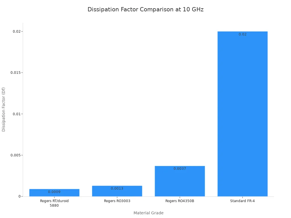
Normal boards soak up too much power. A rogers pcb cuts down this energy loss.
Thermal Management in Harsh Environments
Factory gear gets very hot. Modern boards move heat out fast.
Great heat control keeps parts cool. Your amplifiers run safely for long times.
Important heat facts show this strength:
Glass Transition Temperature (Tg): Passes 280°C. Stays very strong during high heating.
Coefficient of Thermal Expansion (CTE): Reduces physical stress when temperatures change.
Dielectric Stability: Keeps energy loss low in hot heat.
Phase Stability: Protects board power up to 125°C.
Moisture Resistance and Chemical Stability
Soaked up water ruins circuit boards. High humidity breaks standard epoxy resin fast.
Material / Metric | Moisture Absorption Rate | Property Impact |
|---|---|---|
Rogers Materials (General) | 0.02% to 0.08% | Beats wet epoxies with better defense |
RO4350B Specific | 0.04% | Stops Z-axis growth and retains size |
Ceramic/PTFE Composites | Extremely Low | Blocks moisture path to stop power shifts |
Low water absorption stops electrical shorts. It keeps frequencies totally steady.
Low Outgassing in Sealed Industrial Systems
Closed tools trap dangerous gas fumes. Standard boards release bad vapors inside. Vapors leave filth on clear lenses. They dirty high-voltage switches too. A rogers pcb stops gas inside sealed boxes.
Precise Controlled Impedance Performance
Fast circuits need accurate board lines. A steady dielectric constant helps control impedance. You stop bad reflections in RF gear. It brings top power to your machine.
Rogers PCB Materials for Industrial Equipment
Factory tools need special parts for non-stop speed. Regular boards fail from fast signals and heat. Unique rogers pcb options fix these big issues.
RO4000 Hydrocarbon Ceramic Laminates
The RO4000 series joins PTFE traits with fiberglass. You build low-loss boards on normal assembly lines. This mix uses ceramic spheres inside hydrocarbon resin. A steady dielectric constant lasts across hot temperatures.
Performance Metric / Feature | RO4000 Material Mechanism | Operational Benefit |
|---|---|---|
Low Microwave Loss | Uses a resin grid with tiny ceramic beads | Keeps a steady dielectric constant for small power loss |
FR4 Process Compatibility | Non-PTFE composite structure | Allows standard tools to drill, etch, and coat lines |
Machines often pick RO4003C or RO4350B board grades. Both options give strong strength for daily work:
Tensile Modulus: RO4003C stays stiffer at 26,889 MPa than RO4350B.
Tensile Strength: RO4350B pulls stronger at 175 MPa than RO4003C.
Flexural Strength: RO4003C bends at 276 MPa over RO4350B.
Engineering test numbers show these physical and electrical stats:
Parameter / Property | RO4003C Value | RO4350B Value |
|---|---|---|
Process Dielectric Constant (Dk @ 10 GHz) | 3.38 ± 0.05 | 3.48 ± 0.05 |
Design Dielectric Constant (Dk @ 10 GHz) | 3.55 | 3.66 |
Dissipation Factor (tan δ @ 10 GHz) | 0.0027 | 0.0037 |
Thermal Coefficient of Dk (-50°C to 150°C) | 40 ppm/°C | 50 ppm/°C |
Thermal Conductivity (50°C) | 0.71 W/m/K | 0.69 W/m/K |
Coefficient of Thermal Expansion (X / Y / Z axis) | 11 / 14 / 46 ppm/°C | 10 / 12 / 32 ppm/°C |
Volume Resistivity | 1.7×10¹⁰ MΩ | 1.2×10¹⁰ MΩ |
Surface Resistivity | 4.2×10⁹ MΩ | 5.7×10⁹ MΩ |
Copper Peel Strength (1 oz ED Foil) | 6.0 lbs/in (1.05 N/mm) | 5.0 lbs/in (0.88 N/mm) |
Density | 1.8 g/cm³ | 1.9 g/cm³ |
Water Absorption | 0.04% | 0.05% |
RO3000 High-Frequency PTFE Substrates
The RO3000 line offers low-loss PTFE laminates. Select different grades to fit space or heat needs:
RO3003TM: Stops energy loss for signals reaching 10 GHz.
RO3006TM: Uses a 6.15 dielectric constant for amplifiers.
RO3010TM: Gives a cheap choice with a 10.2 constant.
These composite builds keep shapes uniform across different values. Multi-layer designs stay flat without bending or warping.
Rogers Substrate Model | Dielectric Constant (Dk) | Dissipation Factor (Df @ 10 GHz) | Frequency Range & Performance | Thermal & Mechanical Features |
|---|---|---|---|---|
RO3003 | 3.00 | 0.0010 | Low loss past 77 GHz speeds | Low Z-axis expansion protects board holes |
RO3006 | 6.50 | 0.0020 | High-frequency stability for compact layouts | Low Z-axis expansion protects board holes |
RT/duroid Series for Extreme Environments
Pick RT/duroid 5000 or 6000 composites for hard setups. These tough materials boost power efficiency and physical strength.
Main physical and chemical perks include:
Isotropic electric behavior keeps signals predictable across frequencies
High machinability lets teams shape parts with high accuracy
Resists harsh chemical fluids and strong cleaning solvents
Holds steady power performance in very humid air
Yields the lowest loss for strong signal delivery
These bases guard vital tools in outer space setups:
Low dielectric loss protects fast signal path clarity
Low water retention keeps performance stable outdoors
Steady dielectric constant across wide frequency ranges
Meets low outgassing limits for high-reliability space tasks
The RT/duroid line handles severe hazards without breaking:
Passes strict fire tests in high-oxygen areas
Retains strong structure during extreme cold freezing
Low outgassing passes tests for space gear use
Prevents damage when hit by high radiation fields
TMM Thermoset Microwave Materials
Choose TMM microwave laminates when boards face hot cycles. Soft PTFE in RO3000 options can warp over time. TMM blends hard thermoset plastics with ceramic filler particles.
TMM options offer set dielectric constants from 3.25 to 12.80. These boards resist warping and expand like copper lines. You get strong hole connections and easy board builds. Choosing proper high-frequency pcb materials secures every rogers pcb layout.
Key Rogers PCB Fabrication Challenges
Fast boards need special care in shops. Standard factory shops fail on these tools. Learn rogers pcb steps to fix errors.
Specialized Drilling and Machining
Ceramic layers wear out drill bits fast. Ceramic bits dull sharp tools quickly. Dull bits leave rough holes and burrs. Use coated tools for clean holes.
Parameter Category | Recommended Specifications | Application/Notes |
|---|---|---|
Feed Rates | 30 to 70 inches per minute | Slow speeds protect tools from wear |
Tool Coatings & Materials | Diamond-coated or Diamond-Like Carbon (DLC) / Carbide | Tough coatings stop tool damage |
Shops cut drill speeds to lower heat. Clean hole walls help copper stick well.
Lamination and Hybrid Stack-Up Prep
Fast designs mix special layers with FR4. A hybrid rogers pcb lowers total costs. Mixing different layers brings heat growth issues.
Engineering Aspect | Technique / Consideration |
|---|---|
Layer Partitioning | Put fast signals on Rogers layers. |
Thermal Management (CTE) | Match layer growth rates very closely. |
Lamination Process | Press RO4350B under normal FR4 heat. |
Impedance Modeling | Check power rates for each layer. |
Pick good glue films for mixed boards.
Shops use set glue items for layers:
RF Signal Layers: RO4350B layers keep power loss low.
Power Layers: Strong FR4 bases hold parts cheaply.
Interlayer Bonding: Rogers 4450 films glue layers well.
Surface Finishes for High Frequencies
Slick PTFE bases do not hold copper. Copper drops off raw PTFE hole walls. Shops use plasma steps to change PTFE.
Surface Modification: Plasma cleaning helps copper stick to PTFE.
Metallization Preparation: Techs use special copper baths for PTFE.
Treatment Step | Process Purpose & Effect | Role in Hole Plating |
|---|---|---|
Plasma Etching | Makes slick PTFE rough for copper. | Stops copper layers from peeling off. |
Plasma Cleaning | Cleans out tiny drill dust inside holes. | Helps copper form a solid link. |
Good surface care protects every rogers pcb. Smooth metal steps help copper stay put.
Tight Tolerance Etching Controls
Fast signals run along trace edges. Changing trace widths ruins signal path flow. Control metal etching to keep edges straight.
Etch lines use fine film sheets. Close controls keep impedance solid on traces. Precise line shapes stop bad signal bounces.
Selecting Qualified Rogers PCB Manufacturers
Pick top rogers pcb builders for fast boards. Regular factories ruin soft materials. Skilled shops save your board.
RF and Microwave Processing Expertise
Custom rogers pcb work needs special tools. Standard factory chemicals fail on soft bases. Good shops process high-frequency pcb materials safely.
Category | Required Item / Standard | Purpose / Application |
|---|---|---|
Certifications & Standards | ISO 9001 | Checks basic quality rules. |
Certifications & Standards | IPC-6012 Class 3 | Sets hard rules for safe boards. |
Specialized Equipment | Dedicated Plasma Treatment Chambers | Uses gas to prep PTFE holes. Normal steps cannot etch PTFE. |
Specialized Equipment & Software | Modified PTFE Drill Programs | Uses slow drills to stop heat. It stops PTFE smearing. |
Specialized Equipment | Calibrated TDR / VNA Measurement Tools | Tests board impedance on calibrated tools. |
Special gas cleans hole walls. Copper sticks to soft layers.
Advanced In-House Testing Capabilities
Top shops check each rogers pcb with tools:
Vector Network Analyzers (VNAs): Tests fast and stops static damage better than TDRs.
De-embedding Algorithms: Math cuts out extra noise from probes and pads.
Differential PCB Probing: Links tools to test lines for fast differential checks.
These tools fix small signal errors fast.
Material Traceability and Quality Certifications
Good rogers pcb makers track raw sheets. Techs log batch codes for ceramic boards. Tracking stops fake parts from reaching you. You keep your equipment safe with good bases.
Switching to rogers pcb helps your machines.
It keeps industrial gear safe and reliable.
Better rogers pcb designs stop signal loss.
They protect boards from heat failure.
Using RO4000 or RT/duroid improves sensors.
These materials give you peak performance.
Talk to qualified rogers pcb makers early.
They help you design good stack-ups.
Smart teamwork makes rogers pcb production easy.
FAQ
Why pick a rogers pcb over standard FR4?
Normal FR4 loses signal fast at high speeds.
A rogers pcb cuts signal loss.
It also stands up to strong heat.
You keep exact impedance control at high frequencies.
This pick stops costly gear failures.
It makes your machine last longer.
Can you mix rogers pcb and FR4 together?
Yes, shops make mixed boards to save money.
Engineers put rogers pcb materials on fast signal lines.
They use FR4 for basic lower layers.
This smart plan lowers total costs.
It still protects your fast signals.
Do Rogers boards need special tools?
💡 Shops use diamond or carbide drill bits.
Ceramic layers ruin normal drills fast.
Techs also use plasma gas steps.
This prepares smooth PTFE for copper.
How do Rogers boards handle wet air?
Rogers boards soak up almost no water.
They absorb between 0.02% and 0.08% water.
Water changes dielectric values fast.
It distorts your signal paths.
Low water uptake keeps gear safe in wet factories.
See Also
Essential Design Rules And Manufacturing Steps For High Frequency PCBs
Comparing Popular Rogers Materials For Advanced RF Circuit Board Projects
How Rigid Flex Circuit Boards Revolutionize Industrial And Medical Devices
Exploring Key Uses For Advanced Multilayer Circuit Boards Across Industries
Key Manufacturing Guidelines For Industrial Circuit Boards In Harsh Settings
