Thermal Management of PCB Stators
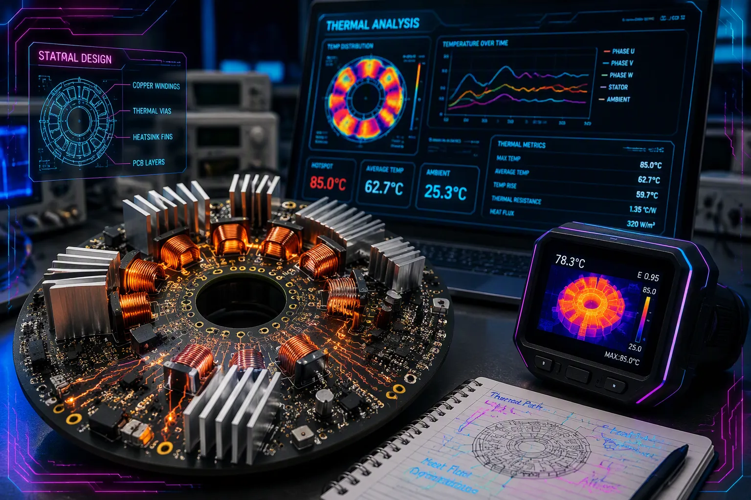
A PCB stator uses copper traces inside it to move heat, like heat pipes. Copper's high thermal conductivity lets these stators send heat to board edges or through layers. Software like PrintStator manages Thermal Management by turning unused copper into thermal pathways. Copper conducts heat at 400 W/mK, while FR-4 ranges from 0.3 to 1 W/mK. This gap shapes every design choice you make. This article compares copper and FR-4 thermal resistance, contrasts PCB stators with traditional wire-wound stators, and shows real examples at 40W and 500W. You will see how a PCB stator moves heat away from areas where it is lost. Each stator design benefits from a continuous copper path.
Key Takeaways
Copper traces inside a PCB stator act like heat pipes. They move heat away from hot spots to the board edges.
PrintStator software turns unused copper into thermal paths. This gives you cooling without adding extra parts.
Copper conducts heat over 1000 times better than FR-4. This huge difference keeps your stator cool.
PCB stators handle high power without fans. A 40W motor runs on an insulated pad. A 500W motor stays cool in a sealed case.
Traditional wire-wound stators trap heat inside. PCB stators channel heat out efficiently. This makes them better for compact, high-power designs.
How PCB Stators Cool
Embedded Copper Traces as Heat Pipes
A PCB stator relies on the copper traces inside the board to move heat. These traces act like solid heat pipes. They create a continuous path from the hot spots to the outer edge. ECM developed this thermal design:
ECM has developed a thermal design which has a continuous copper path from the parts of the stator where losses originate to the interface to the case. This is possible because our software, PrintStator, can identify unused spaces and shape the copper that do not carry current function into 'heat pipes.' These non hollow, 'heat pipes', are using the copper to conduct the heat from the center of the stator to the outside edge where the stator is clamped into the case and the heat can be rejected to ambient. They are also functioning in the Z direction to bring the heat to the top and bottom layer of the board.
This design gives you a direct thermal path. The copper runs without breaks. Heat flows along the trace just like water flows through a pipe. PrintStator software finds every piece of inactive copper. It shapes that copper into thermal lanes. This method works because copper has a thermal conductivity near 400 W/mK. That value is over a thousand times higher than FR-4. Heat moves fast through the copper and spreads across the board. The design also pushes heat in the Z direction. It sends heat to the top and bottom layers of the PCB. This vertical movement gives you extra paths to remove heat from the core.
Channeling Heat to Edges and Layers
After the copper collects the heat, you must push it out. The flat board geometry makes this easy. PCB stators have a large surface area relative to their thickness. This shape helps PCB stators spread heat across the whole board. Heat travels from the inner layers to the outer edges. You clamp a stator into a case at those edges. The case acts as a large heat sink. It takes heat from the board edge and sends it to the surrounding air. This clamping method creates a solid thermal connection.
The thermal path works in two directions. First, heat moves horizontally along the copper to the board edges. The large surface area helps this movement. The broad, flat shape gives heat room to spread before reaching the edge. Second, heat moves vertically through the layers. It uses thermal vias and the copper itself. This vertical movement brings heat from inner layers to the outer surfaces. You get better heat distribution across the entire PCB stator. This thermal management method does not need extra parts like fans. The PCB handles the job alone.
When you clamp the board into a case, the copper path contacts the case directly. This contact creates a low resistance path for heat to leave. The same principle works at 40W or 500W. The large surface area keeps thermal performance stable under high loads. You can push more current through the motor without overheating.
PrintStator builds this design from the start. Every trace and via carries current and moves heat. The inner and outer end turns of the stator coils are key areas. They generate the most heat due to high current density. The traces around the inner and outer end turns maximize heat extraction. You get a board that runs efficiently and stays cool.
Creating Embedded Heat Pipes
Utilizing Inactive Copper
PrintStator software finds copper on your pcb stator that carries no current. It then changes that unused copper into thermal paths. This step turns dead copper into working heat pipes. You get a steady thermal route without adding parts or layers.
The software finds unused spaces across the board. It shapes those areas into copper lanes that move heat. These lanes link hot spots to the board edge. They also push heat through the Z direction to outer layers. This approach works on any pcb stator design. You gain thermal performance from copper you already have.
Design Rules for Thermal Traces
Thermal trace geometry follows strict rules. You must maximize active copper inside the magnet sweep area. At the same time, you respect fabrication clearances and insulation needs. Place via layer transitions where they avoid current crowding, weak annular rings, or asymmetric loops. Never set current rating from trace width alone. Derive the allowable current from verified winding temperature under your load profile and cooling conditions.
Multi-via structures reduce current crowding and lower losses. Vertical copper post arrays with 0.3–0.6 mm diameter and an aspect ratio of 3:1 to 5:1 connect 4–6 inner copper layers in parallel. These arrays increase effective conductor cross-section by 150–200% versus single-layer 105 μm copper. Thermal via arrays of 0.2–0.3 mm diameter with 0.6–0.8 mm spacing surround each post. They lower thermal resistance by 35–45%. The overall effect: current capacity rises 180–220% with no extra assembly steps.
Design Variable | Benefit | Trade-off / Constraint |
|---|---|---|
Wider or thicker copper | Lower DC resistance and reduced temperature rise | Larger coil area, tighter spacing, and manufacturing limits |
More PCB layers | More active copper within the same diameter | Via transitions, alignment, cost, and circulating-current risk |
Smaller air gap | Stronger magnetic coupling | Greater sensitivity to warpage, runout, particles, and assembly tolerance |
For unusually high current, temperature, or layer count, submit your stackup and conductor geometry to the PCB fabricator before finalizing the electromagnetic model. This step prevents invalid resistance, air-gap, and thermal calculations.
PCB Thermal Design Techniques
Thermal Vias, Heavy Copper, and Copper Coins
You have a few ways to remove heat from a pcb stator. Thermal vias carry heat between layers. Heavy copper gives heat more metal to move through. Copper coins put solid metal blocks into the board for direct heat transfer. Each method works best in different places.
Thick copper traces are needed to move heat well from the inner layers to the outside. If your traces or parts make a lot of heat, the board needs thick traces to send that heat out, usually through via-holes. A 10-layer pcb is one of the best choices for many electronic uses because it gives great thermal dissipation and low signal loss.
Multi-via structures also cut losses. They reduce current crowding and lower resistive heating at the source. This loss-reduction method helps thermal management by making less heat in the first place.
IMS Materials and Stackup Planning
Insulated metal substrate materials give you another path. Iron base copper clad material works as both pcb and small motor stator substrate. Iron base PCB fits brushless DC motors and spindle motors. Silicon steel base PCB has better magnetic properties than iron base copper clad plate. These materials help stators release heat through the metal backing.
Stackup planning brings everything together. Your laminate system sets thermal and mechanical behavior. Copper weight and layer count control resistance and heat spreading. Core and prepreg thickness shape the magnetic gap. Via structure links coil sections and allows heat conduction. Surface protection defines insulation and thermal margin. Send your proposed stackup and conductor geometry to the fabricator before you lock in the electromagnetic model. A capability assumption that changes later can ruin resistance, air-gap, and thermal calculations all at once.
Thermal Resistance Comparison
Copper vs. FR-4 Conductivity
When you design a PCB stator, material choice drives thermal performance. Copper delivers a thermal conductivity near 400 W/mK. FR-4, the standard board material, offers only about 0.3 W/mK. That gap exceeds a factor of one thousand. Copper moves heat like a highway. FR-4 blocks it like a wall.
This performance gap shapes how you manage heat. A single copper trace pulls heat away from hot coil areas. FR-4 alone traps that heat inside the board. Heat builds up and stresses the motor. So you rely on copper to move heat across the board surface. The idea of thermal resistance helps you understand this concept. It measures how much a material resists heat flow. Copper has low thermal resistance. Heat moves through it easily. FR-4 has high thermal resistance. Heat stays trapped. When you embed copper traces inside the FR-4 board, you create a low-resistance route. Heat follows that route out of the system.
Think of it like a wire for electricity. A thick copper wire carries current with low resistance. A thin FR-4 sheet blocks current. The same principle applies to heat. Copper gives heat a clear path to follow. Each PCB functions as both a circuit carrier and a heat sink.
PCB Stator Technology vs. Wire-Wound
PCB stator technology differs from traditional wire-wound designs in one key area: heat control. A wire-wound design uses copper wire wrapped around iron teeth. Multiple insulation layers trap heat. The wire has limited contact with the case or air. Heat builds up inside the windings. It has no easy escape path.
PCB stator technology solves this problem. The copper traces lie flat on the board layers. They touch the FR-4 and other copper layers directly. This contact makes a thermal bridge. Heat moves from the traces into the board. It then flows to the edges. You clamp the board to a case. The case pulls heat away.
Wire-wound designs also release more energy as heat. The reason relates to torque delivery. A wire-wound design creates torque through magnetic fields. But the fields lack precision. Some energy turns into heat instead of motion. PCB stator technology delivers torque more efficiently. Less energy becomes heat. More energy becomes useful work.
This efficiency comes from the precise layout of stator windings. You can shape each trace exactly. You can optimize the geometry for magnetic performance. This reduces losses in the copper and the iron. The motor runs cooler at the same power level. Any stator must manage the heat it generates. A stator design must balance electrical and thermal performance. PCB stators waste less. They achieve this through better winding design and better heat removal. Traditional designs trap heat inside the windings.
The practical result matters for your design. A 40W motor using a PCB stator can run on an insulated pad without overheating. A wire-wound design at the same power may need forced air cooling. At 500W, the difference grows. PCB stators can run inside a sealed case. Wire-wound designs often need fans or liquid cooling.
The printed circuit board does more than hold components. It works as a thermal management system. The copper traces, the vias, and the layers all cooperate. They move heat away from the source. They keep the stator cool under load.
When you compare a design built on a PCB with one built from wound wire, the winner for heat control is clear. The PCB version uses copper to conduct the heat out of the motor. The wire version leaves heat trapped inside. This advantage makes PCB stator technology the right choice for high-power, compact motor designs.
Real-World Cooling Examples
40W on an Insulated Pad
A 40W pcb stator motor running on an insulated pad shows how well this design handles heat. The pad blocks heat from leaving through the bottom. So heat is mostly internal. The copper traces still move heat to the board edges. Air around the edges takes that heat away. You get stable operating temperatures without fans or vents.
This setup proves the thermal management works even in poor conditions. The board spreads heat across its flat surface. The large area gives heat dissipation capacity a boost. You can run the motor for hours on that pad. The stator stays cool enough to touch. No localized overheating appears. This result shows how pcb stator motors cooled by copper traces handle real loads.
500W in a Case
A 500W pcb stator motor inside a case faces a harder test. The case traps air and limits airflow. But the stator is clamped into the case at its edges. That clamp creates a solid stator to case connection. Heat flows from the copper traces to the case wall. The case then releases that heat to the outside air.
The continuous copper path makes this possible. It carries heat from the coil centers to the interface to the case. From there, heat can be rejected to ambient. The stator is clamped into the case with enough pressure to keep that path tight. This design gives the motor a strong thermal safety factor. You can push more current through the pcb stator without risking damage. The thermal performance stays steady at 500W.
Thermal dissipation limits how much current you can run through any pcb stator motor. Better heat removal means more power. These two examples show how pcb stator motors cooled by embedded copper handle both low and high loads. Heat can be rejected to ambient in both cases. That ability makes the difference.
PCB stators use embedded copper traces as heat pipes. They leverage copper's high thermal conductivity to move heat to edges or through layers. PrintStator creates these thermal paths from inactive copper on your board. This efficient thermal management relies on copper's 400 W/mK conductivity versus FR-4's 0.3 W/mK. Traditional wire-wound designs trap heat inside windings. A PCB design channels it away efficiently. A 40W motor runs stable on an insulated pad without any fans. A 500W stator stays cool inside a sealed case clamped at the edges of the board. These two examples prove that effective thermal management works in real high-power applications. The design delivers reliable cooling without extra hardware or additional airflow.
FAQ
How do copper traces act as heat pipes inside a PCB stator?
Copper traces form a continuous path from hot spots to the board edge. Heat flows along this path like water through a pipe. The copper then carries heat to the case interface. From there, the case rejects heat to ambient air.
What role does PrintStator play in thermal management?
PrintStator finds copper that carries no current. It reshapes that inactive copper into thermal lanes. These lanes link hot areas to the board edges and outer layers. You gain cooling performance without adding parts or extra layers.
Why does copper beat FR-4 for heat removal?
Copper conducts heat at roughly 400 W/mK. FR-4 sits near 0.3 W/mK. That gap exceeds a factor of one thousand. Copper moves heat fast. FR-4 traps it. Embedded copper traces give heat a low-resistance route out of the board.
Which design techniques improve PCB stator cooling?
Thermal vias carry heat between layers. Heavy copper adds more metal for heat flow. Copper coins create direct metal paths. IMS materials release heat through a metal backing. Multi-via structures also cut resistive heating at the source.
Can a PCB stator stay cool at high power without fans?
Yes. A 40W motor runs stable on an insulated pad with no airflow. A 500W stator stays cool inside a sealed case. The continuous copper path carries heat to the clamped case edges. Thermal dissipation sets the current limit, not the cooling hardware.
See Also
Investigating How Aluminum PCBs Achieve Thermal and Electrical Efficiency
Applications and Benefits of Copper-Based PCB Thermoelectric Separation Process
Understanding Why Ceramic PCBs Are Superior for Effective Heat Dissipation
High TG FR4 Laminate PCBs Deliver Superior Performance in Extreme Temperatures
A Guide to Production Technology for Heavy Copper Multilayer PCBs
