AI Server PCB: High-Layer & High-Speed Solutions
You see fast changes in ai server pcb designs as technology gets better. High-layer means you use boards with 24 to 40 layers or even more. High-speed means the boards can handle signals like 56G, 112G, or 224G PAM4 SerDes.
Aspect | High-Layer Definition | High-Speed Definition |
|---|---|---|
Layer Count | 24 to 40 (40+ in advanced server setups) | 24 to 36 (40+ for 112G/224G ASICs) |
Typical Signaling | PCIe, memory buses, accelerator links | 56G/112G/224G PAM4 SerDes |
These features help you get more processing power, lower wait times, and make your systems bigger. You can run real-time AI, work with big sets of data, and connect strong CPUs, GPUs, or TPUs. You also use faster storage and networking to move data quickly.
High-density computing puts more power in a small space.
Lower latency gives faster answers for AI jobs.
Scalability lets you make your setup bigger when needed.
Good networking and storage move data fast.
Key Takeaways
High-layer PCBs with 24 to 40 layers help AI servers connect many parts well.
Using low-loss materials like Megtron 7 keeps signals strong at fast speeds like 112G and 224G. It also helps stop data from getting lost.
Good thermal management uses thick copper layers and heat pipes. This is important because AI chips need a lot of power.
HDI technology makes signal paths shorter and adds more connections. This helps AI servers work better and be more reliable.
Modular daughterboards make upgrades and repairs easy. This makes it simple to improve what AI servers can do.
AI Server PCB Requirements
High-Layer Stack-Ups
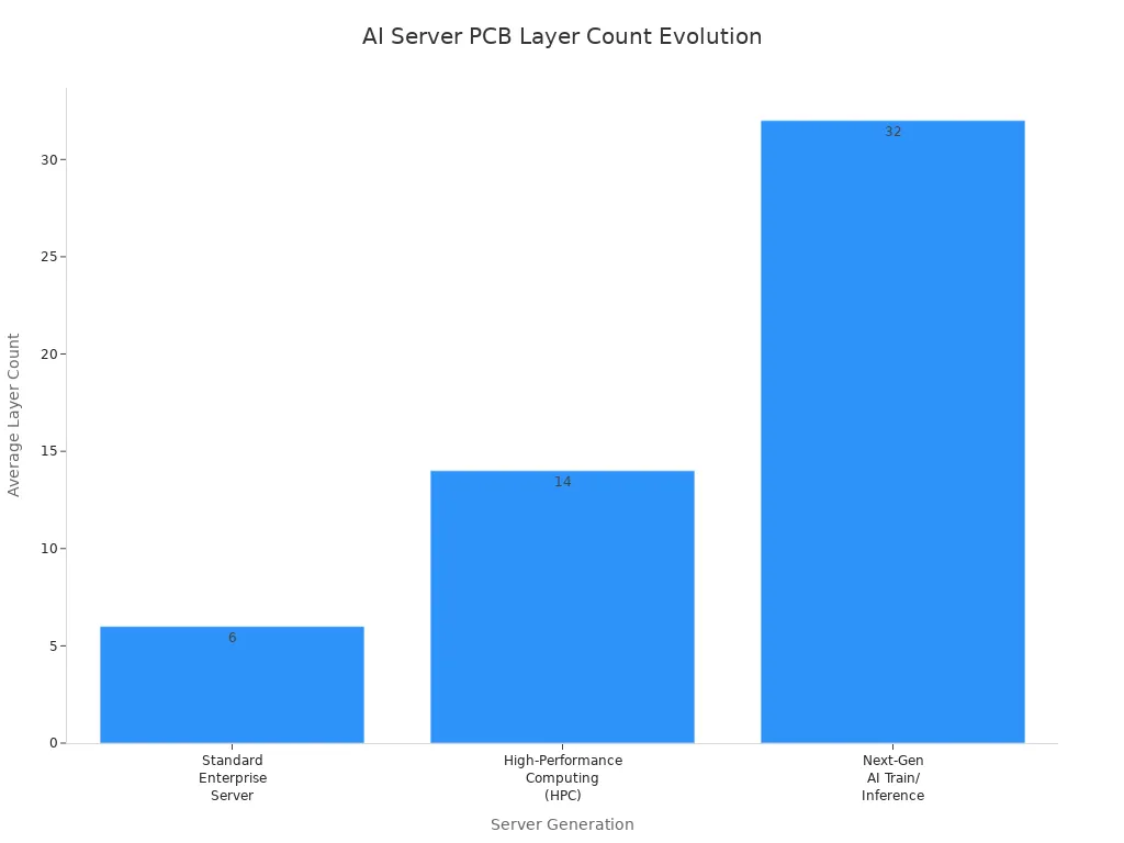
You need more layers in your ai server pcb for today’s ai servers. Most new ai server pcb designs use between 24 and 40 layers. Having lots of layers helps connect CPUs, GPUs, memory, and fast data lines. This is because ai servers need more connections and higher density.
Generation | Average Layer Count | Data Rate Support |
|---|---|---|
Next-Gen AI Train/Inference | 28 to 36+ layers | 224G PAM4 |
Comparison Area | AI Server PCB | Traditional Enterprise PCB |
|---|---|---|
Typical Layer Count | 20–36 layers | 8–16 layers |
Data Rate Support | 112G PAM4 / 224G PAM4 | 10G–56G NRZ/PAM4 |
Ai server motherboards and GPU backplanes use these high-layer stack-ups. Extra layers help keep power, ground, and signal paths apart. This lowers interference and makes the board work better. High-density interconnect (HDI) technology lets you fit more connections in a small space. HDI uses microvias and thin lines to link layers, which helps with density and signal quality. Thick copper layers carry more current and spread heat well.
Layer Count | Configuration Description |
|---|---|
4-Layer | Top: Signal, Inner 1: Ground, Inner 2: Power, Bottom: Signal |
6-Layer | Top: Signal, Inner 1: Ground, Inner 2: Signal, Inner 3: Power, Inner 4: Ground, Bottom: Signal |
10-Layer | Multiple signal, ground, and power layers with attention to impedance control |
22-Layer | Highly complex with 22 conductive layers, used in AI servers and high-performance systems |
Note: You see high-layer stack-ups in ai server pcb designs for high-performance computing, telecom, aerospace, and advanced medical equipment.
High-Speed Data & SerDes
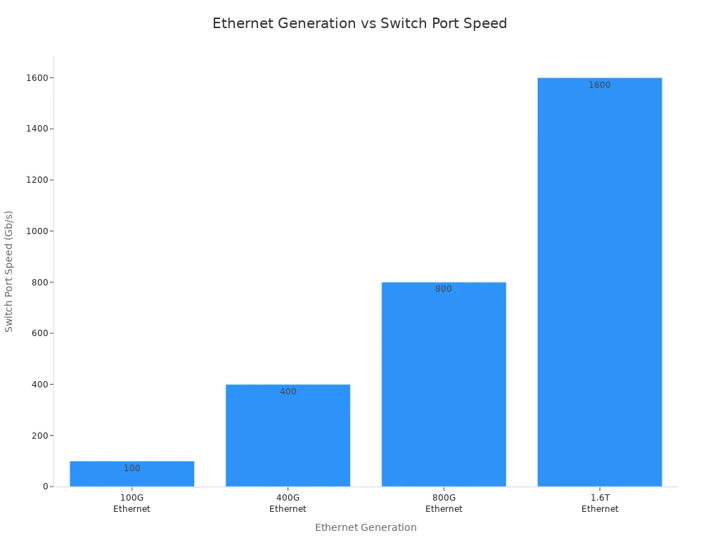
You must support high-speed data in the ai server market. New ai server pcb designs use SerDes links that reach 112G or even 224G PAM4 speeds. These fast data rates move lots of information between CPUs, GPUs, and network switches.
Ethernet generation | Switch port speed | Typical SerDes signaling |
|---|---|---|
100G Ethernet | 100 Gb/s | 25G NRZ |
400G Ethernet | 400 Gb/s | 56G PAM4 |
800G Ethernet | 800 Gb/s | 112G PAM4 |
1.6T Ethernet | 1.6 Tb/s | 224G PAM4 (emerging) |
You need low-loss materials like Megtron 7 or Tachyon 100G to keep signals strong. These materials cut down on signal loss and crosstalk. This keeps your high-speed data clean and reliable.
To make sure signals get to the receiver, you must use ultra-low-loss PCB materials like Megtron 7 or Tachyon 100G. These materials lower dielectric loss (Df) and keep signals strong.
You also need to control impedance and use good stack-up designs. This stops signal reflections and errors. HDI technology, with short and direct connections, helps signals stay strong at high speed.
Power & Thermal Demands
You face big power and heat problems in ai server pcb designs. AI chips can use 300 to 500 watts each. One board can use 1000 to 3000 watts. This high power makes hot spots that are hard to cool.
Feature | AI Server PCBs | Traditional Server PCBs |
|---|---|---|
Power Density | 1000W to 3000W+ per board | 200W–800W |
Copper Plane Thickness | 2 oz, 3 oz, or 4 oz | 1 oz |
Thermal Management | Heavy copper layers, embedded copper coins | Standard aluminum heatsinks and air fans |
Thermal Load Management | Solid copper coins for high-TDP components | Conventional cooling methods |
You need thick copper layers to carry more current and spread heat. You also use thermal vias, vapor chambers, and sometimes liquid cooling to keep things cool. These cooling methods help with the heat from powerful chips.
Thermal vias move heat to inside copper planes.
Vapor chambers and heat pipes spread heat across the chassis.
Cold plates with liquid coolant cool high-power accelerator cards.
Vertical Power Modules (VPMs) and good power networks lower losses and keep voltage steady.
Tip: Small designs make cooling harder, so you should plan your power and cooling early.
You see that ai server pcb requirements make you use more layers, faster speeds, and better materials. You must balance density, power, and heat to keep your systems fast and reliable.
Design Challenges
Signal Integrity Issues
When you design high-speed, high-density PCBs, you face many signal integrity problems. High-frequency signals can get weaker as they move through the board. This is called signal attenuation. When signals get weak, sharp edges become rounded. This makes it hard for your system to read data. Impedance mismatches are another problem. If impedance changes along the path, signals bounce back. This causes distortion and errors. You must keep impedance very close to the right value, usually within plus or minus 5 percent. Crosstalk is also a big issue. When traces are too close, energy can jump from one line to another. This makes noise and can cause mistakes. You can lower crosstalk by keeping traces apart, using ground planes, and putting signals on different layers. These steps help your connections stay clean and work well.
Signal attenuation makes data quality worse.
Impedance mismatches cause signals to bounce and make mistakes.
Crosstalk adds noise and timing problems.
Tip: Try the 3W rule for trace spacing and use solid ground planes to lower crosstalk in your design.
Material & Loss Constraints
The materials you pick change how well your ai server pcb works and how much it costs. You want materials with a low dielectric constant so signals move faster. A low dissipation factor keeps signal loss small. This is important for high speed and low wait times. Thermal stability is also needed because server boards get hot. High-performance materials like Rogers or Megtron work well but cost more than regular FR4. You can save money by using Rogers for high-speed layers and FR4 for power layers. This keeps performance high and costs lower. Tests show Rogers boards lose up to 35 percent less signal than FR4. This helps your connections stay strong.
Material Property | Description |
|---|---|
Low Dielectric Constant | Makes signals move faster and lowers delay. |
Low Dissipation Factor | Keeps signal loss small for fast data at high speeds. |
Thermal Stability | Handles heat from server parts without breaking down. |
Manufacturing Limits
Making high-density, high-layer PCBs has its own limits. You might need up to 36 layers for an AI server motherboard. Trace widths can be as small as 30 microns. Small spaces make routing and design very hard. You must keep everything lined up and working together. Large fine-pitch BGA pads connect GPUs. Wide copper planes give steady power. Good thermal management, like thermal vias and smart stack-ups, helps control heat. High-density interconnect designs let you fit more routes, but they also make building the board harder and cost more.
Application | Layer Count Range | Trace/Space (microns) |
|---|---|---|
AI server motherboard | 20-36 | 75/75 or 50/50 |
OAM accelerator module | 18-30+ | Below 30/30 |
Note: When you want more speed and density, you must balance how well it works, how much it costs, and how easy it is to make in every design choice.
PCB Types for AI Servers
HDI & Multilayer Boards
When you design an ai server pcb, you pick between HDI and regular multilayer boards. HDI boards have shorter paths for signals and can fit more routes. This means signals travel faster and there is less interference. You get better speed for high-speed data, which is important in AI servers. HDI boards also let you add more connections in a small space. The need for HDI printed circuit boards is growing because AI servers are getting more complex. HDI boards are now very important for both AI and 5G systems. You see them used in places where speed and reliability are needed most.
HDI boards have shorter signal paths and more routes.
HDI helps lower delay and interference.
The HDI market supports complex AI server needs.
HDI boards are now key for AI and 5G.
Backplane & Daughterboard Roles
In a server motherboard, you find both backplanes and daughterboards. The backplane is like a main road for data. It links CPUs, GPUs, memory, and storage together. High-layer backplanes handle fast signals and lots of power. Daughterboards plug into the backplane to add new features. These features can be extra networking, storage, or AI accelerators. You can swap out daughterboards without changing the whole motherboard. This makes upgrades and repairs much easier.
Board Type | Main Function | Typical Use Case |
|---|---|---|
Backplane | Main data and power distribution | Server motherboard, AI server pcb |
Daughterboard | Adds features or upgrades | Networking, storage, AI accelerators |
Tip: Modular daughterboards help you upgrade your system fast and keep downtime low.
Application-Specific Needs
You need to match your PCB design to what your AI system does. For AI inference servers, you use new materials that keep signals strong and lower heat. This helps your system work well even when it is busy. Edge computing and 5G need small, powerful boards. These boards move data quickly and keep wait times short. Many companies now use eco-friendly ways to make boards and save energy. This saves money and is good for the planet. Custom and modular designs let you upgrade and grow your hardware faster. With these flexible boards, you can launch new AI products quickly.
New materials keep signals strong and lower heat for inference servers.
Small, powerful PCBs help edge computing and 5G.
Eco-friendly and energy-saving designs cut costs and help the planet.
Custom and modular PCBs make upgrades and growth easier.
PCB Materials & Stack-Up
Low-Loss Material Choices
You need to choose the right high-speed materials for your AI server motherboard. These materials help signals stay strong as they move across the board. Modified low-loss FR4 works well for most server boards. Very-low-loss laminates are best for high-speed chips and SerDes layers. PTFE is used for RF paths because it has the lowest loss. The table below lists common high-performance PCB materials and their features.
Material Category | Typical Use | Characteristics |
|---|---|---|
Modified low-loss FR4 | Mainstream server boards | Dk ≈ 3.6–3.8, Df ≈ 0.005–0.009 |
Very-low-loss laminates | High-speed SerDes layers | Used for 112G PAM4 channels |
PTFE | RF or microwave signal paths | Df ≈ 0.0002-0.001, Dk ≈ 2.1-3.0 |
You can see that high-speed materials keep your data clean and reliable. When the frequency goes up, you need materials with lower loss to keep up with speed.
Stack-Up for High-Speed
Stack-up design changes how well signals travel at high speed. You can use different stack-up types for different needs.
4-layer stack-up works for low or medium frequency. It does not shield fast signals very well.
6-layer stack-up gives better shielding and controlled impedance for medium high-speed designs.
8-layer stack-up is best for very high-speed designs. It gives more options for matching impedance and keeping signals apart.
You should put high-speed signal layers next to solid ground or power planes. This keeps signal integrity strong. If you put high-speed layers together without a reference plane, you get crosstalk problems. The stack-up controls the space between signal layers and reference planes. This changes impedance and EMI behavior.
Reliability Factors
You need to think about reliability when you pick materials and stack-ups for high-performance computing. Signal integrity needs controlled impedance and less crosstalk. Power integrity means your power network stays steady and noise stays low. Electromagnetic compatibility stops interference from hurting your board. Thermal performance matters because high-speed chips make heat. You manage heat with copper planes, thermal vias, and good material choices. Layer stack-up and routing help balance signal routing, grounding, shielding, and how easy it is to make.
Impedance control: Figure out trace width and dielectric thickness.
Routing strategy: Keep high-speed traces short and straight.
Stack-up design: Give signals the shortest return path and control EMI.
Surface finish: Pick finishes that do not weaken signals.
Drilling and plating: Make sure via walls are smooth and copper thickness is even.
Consistency assurance: Ask your PCB supplier for strict process control and inspection.
Tip: You can make your board more reliable by planning your stack-up and material choices early in your motherboard design.
Design Best Practices
HDI & Layer Management
You must manage layers and HDI with care. Start by putting signal and ground layers next to each other. This keeps impedance steady and helps signals stay strong. Wide power and ground planes give steady current and cut down noise. Keep analog, digital, and high-speed parts apart to stop interference. Pick vias that are simple and save money. Choose parts that work well and are easy to make. Careful design lowers stress, EMI, and signal problems. Make stack-ups that fit your budget and needs. Always think about cooling and if materials work together. Follow IPC rules so your motherboard is easy to build and lasts long.
Tip: Good layer management makes signals stable and keeps your board cool in ai electronics.
Power Delivery & EMI
You must build power networks that work fast. Keep power and return paths short and straight. This helps current move quickly when loads change. Use a solid ground plane to stop high-impedance paths and lower EMI. Put decoupling capacitors close to fast chips to cut noise. Use thick copper layers and keep power and ground planes close. This lowers impedance and spreads power well. These steps help your board work at high frequency and stay stable.
Short loops give better power delivery.
Strong ground planes lower EMI.
Decoupling capacitors help control noise.
Thick copper and close planes manage power impedance.
Thermal Solutions
You face big heat problems in ai electronics. Use heat pipes and vapor chambers to move heat away fast. Immersion cooling works well by putting PCBs in special fluids. Place high-power parts in smart spots to stop heat from building up. Pick thick copper layers to spread heat across the board. Choose board materials that move heat well. Make airflow in cases to stop heat from getting trapped. Add sensors to check temperature in real time. These ideas help your motherboard stay cool and work well at high frequency.
Note: Good cooling makes your hardware last longer and helps real-time jobs in tough places.
You can build reliable AI server PCBs by choosing the right materials and stack-up. Use modified FR4 for most high-speed digital boards. For higher speeds, pick low-Dk/Df FR4 or hybrid stack-ups. PTFE or Rogers work for special needs. See the table below for quick guidance:
Material Type | Application |
|---|---|
Modified FR4 | High-speed digital PCBs for AI servers |
Low-Dk/Df FR4 | High-speed/high-frequency PCBs |
PTFE/Rogers materials | Advanced applications, but rarely used |
Hybrid stack-up | Combination of PTFE and FR4 for high-speed PCBs |
Plan your stack-up early. Keep power, signal, and ground layers well organized. Follow best practices to keep your AI systems fast and dependable.
FAQ
What is a high-layer PCB, and why do you need it for AI servers?
You use high-layer PCBs to connect many chips and parts in a small space. These boards have 24 or more layers. More layers help you manage power, signals, and heat in AI servers.
How do you keep signals strong at 112G or 224G speeds?
You pick low-loss materials like Megtron 7. You use short, direct traces and control impedance. These steps help you keep signals clear and fast.
What makes HDI boards important for AI server PCBs?
HDI boards let you fit more connections in less space. You get shorter signal paths and less interference. This helps your AI server run faster and more reliably.
How do you manage heat in high-power AI server PCBs?
You use thick copper, thermal vias, and heat pipes. You place hot parts smartly and use airflow or liquid cooling. These methods help you keep your board cool.
Can you upgrade AI server PCBs easily?
Yes! You can use modular daughterboards. These boards let you add or swap features like storage or accelerators. You upgrade your system without changing the whole motherboard.
See Also
Understanding High-Speed PCBs: Key Features And Benefits
Top Materials Recommended For High-Speed PCB Development
The Importance Of High-Speed PCB Design Explained