Building Reliable Automotive PCBs with Advanced Design Strategies

You rely on automotive electronics to keep drivers safe. These electronics also help cars work well. Advanced design strategies in automotive pcb design help you make reliable products. They prepare for tough environments, like fast temperature changes or strong shaking. When you pick materials with matching thermal properties and plan the pcb layout well, you lower risks like solder joint fatigue or layer delamination. Using proven methods from aerospace, you build automotive pcb solutions that survive extreme conditions and give steady performance.
Key Takeaways
Automotive PCBs face tough conditions like heat, moisture, and vibration. Make them strong and dependable.
Follow strict rules like AEC-Q100 and ISO 26262 for safety and performance. Testing is very important for reliability.
Use advanced ways to manage heat so boards do not get too hot. This means using thermal vias and materials that spread heat well.
Pick good materials with strong thermal properties. This helps boards last longer and work better in hard places.
Use quality checks like Automated Optical Inspection (AOI) to find defects early. This lowers failures and makes boards more reliable.
Automotive PCB Reliability Challenges
Environmental Stress Factors
When you design automotive pcbs, you deal with many stress factors. These boards have to work inside cars that get hot, wet, dusty, and shake a lot.
Water can get inside and make the boards rust.
Dust can pile up and stop signals from moving.
Power spikes can break important parts.
Heat can make solder joints weak.
Shaking can crack lines and loosen parts.
Automotive pcbs must handle big temperature changes and lots of shaking. These things are harder on boards than in most other jobs. You have to make sure your boards stay strong and work well, even when things get rough.
Safety and Functional Demands
Automotive electronics are very important for safety. These boards help with airbags, crash sensors, and driver help systems. If a pcb stops working, it can cause big problems. The rules for car boards are very strict. You have to follow tests for heat, shaking, and electrical noise.
Standard | Key Requirements |
|---|---|
AEC-Q100 | Thermal Cycling, High-Temperature Operating Life, Electrostatic Discharge Protection, Mechanical Vibration and Shock Resistance |
AEC-Q200 | Damp Heat Test, Thermal Shock, Mechanical Stress, Resistance to Soldering Heat |
ISO 26262 | ASIL classification, FMEA, Design Assurance |
IPC-2221 | Thermal Management, Vibration Resistance, Signal Integrity |
ISO 16750 | Temperature and Humidity, Mechanical Vibration and Shock, EMI Testing |
You need to test your boards to pass these rules. This makes sure they work well and last long in all cars.
Common Failure Modes
You should know the main ways automotive pcb assemblies can fail. These problems can hurt how the boards work and keep people safe. The table below lists the main types:
Failure Mode | Description | Percentage of Total Failures |
|---|---|---|
Causes solder joint fatigue and component degradation due to extreme temperatures. | N/A | |
Vibration and Mechanical Stress | Leads to cracked solder joints and broken traces, accounting for 20% of failures. | 20% |
Electrical Overstress (EOS) | Results from voltage/current beyond design limits, damaging sensitive components. | N/A |
Corrosion and Environmental Damage | Increases resistance and leads to signal loss due to moisture and contaminants. | N/A |
Manufacturing Defects | Introduces intermittent or permanent failures due to poor fabrication. | N/A |
You have to design your boards to stop these problems. This helps you reach the high reliability that new cars need.
Design Strategies for Automotive PCB Reliability
Automotive Standards Compliance
You have to follow strict rules when making automotive pcb assemblies. These rules help your boards work well for a long time in cars. AEC-Q100 is a key rule for making sure your boards are reliable. It checks the parts you put on your boards. AEC-Q100 has many tests, like:
Wire Bond Shear Test (Q100-001)
Human Body Model Electrostatic Discharge Test (Q100-002)
IC Latch-Up Test (Q100-004)
High-Temperature Operating Life (HTOL) for up to 1,000 hours
You need to pick the right grade for your job. Grade 0 works from -40°C to +150°C and is good for engine control units. Grade 1 covers -40°C to +125°C and fits under-hood electronics. Grade 2 and Grade 3 are for places inside the car that are not as tough.
AEC-Q100 works with ISO 26262, which is a safety rule for car electronics. Your boards must pass hard tests for heat, shaking, and electric stress. If you follow these rules, your boards last longer and keep people safe.
Standard | Impact on Reliability | Description |
|---|---|---|
ISO 26262 | Makes things safer by checking for dangers and problems | Helps stop big failures in important electronic parts. |
IPC-6012DA | Makes sure boards are strong and made well | Gives rules for how boards should work, so they do not break easily. |
AEC-Q100 to AEC-Q200 | Sets up the same tests for all parts | Makes sure parts work well even when things get rough, so boards are more reliable. |
Thermal Management in Automotive PCB Design
You need to control heat in your automotive pcb design. Good thermal management keeps your boards working and stops them from breaking early. There are ways to move heat away from hot spots:
Put thermal vias under hot parts to move heat down.
Use board materials that move heat well, like metal-core pcbs or thick copper.
Use thicker copper and wider lines to help spread heat.
Keep hot parts away from parts that can get hurt by heat.
Use big copper areas to help heat move out.
Plan for air to move so heat does not get stuck.
Thermal simulation helps you find hot spots before you make the boards. This saves you money and time because you can fix problems early. It also helps stop failures in the field. Using new materials helps heat move out faster. For example, graphene-enhanced compounds and ceramic boards work well in electric cars and power electronics.
Material Type | Heat Dissipation Efficiency | Notes |
|---|---|---|
Copper-filled thermal vias | High | Moves heat well for parts that get very hot. |
Graphene-enhanced compounds | Very High | Helps heat move from parts to heat spreaders. |
Phase-change materials | High | Good for handling heat when things change temperature. |
Metal-core PCBs | Superior | Moves heat better than regular board materials. |
Ceramic substrates | Exceptional | Best for important jobs like electric car inverters. |
Vibration and Shock Resistance
Automotive pcb design needs to handle lots of shaking and bumps. You can add ribs, frames, or more layers to make boards stronger. These things stop the board from bending or breaking. You should use strong materials like FR4, polyimide, and ceramics. These materials can take heat and stress.
You need to test your boards with heat and shaking tests. These tests show if your boards can last in real cars. Making boards stronger against shaking and bumps means fewer failures. This can lower warranty claims by up to 22% for car electronics. It also saves money for car companies and keeps drivers safe.
Better P-N junctions can cut warranty claims by 15% for electronics makers.
In cars, stronger junctions mean 22% fewer failures in tough conditions.
This can save about $420 million each year in recall and warranty costs for car makers.
Material Selection for Reliability
You need to pick the best materials for your automotive pcb. Good materials have high glass transition temperatures (Tg), stay strong in heat, and do not let water in. These things help your boards last longer and work better in hard places.
Material | Tg (°C) | Td (°C) | Z-axis CTE (ppm/°C) | Key Features | Typical Applications |
|---|---|---|---|---|---|
AUTOLAD 1 | 160 | 348 | 37 / 230 | Strong, keeps water out, works well in heat | Car control systems, body electronics |
AUTOLAD 1G | 173 | 400 | 35 / 189 | No halogen, better in heat | Car electronics, camera modules |
AUTOLAD 2G | 190 | 402 | N/A | Good for high CTI, lasts in tough places | Power electronics, high-reliability jobs |
FR-4 | 170+ | N/A | N/A | Cheap, works well for less hard jobs | Easier car electronics |
Polyimide is good for hot places, like engine control units.
Ceramic materials are best for heat in power electronics.
Metal-core pcbs help with heat in LED lights and power circuits.
When you use good materials, your boards break less and cost less to fix. Spending more at first saves money over the car’s life. It also makes boards easier to put together and helps them work better.
Tip: Always pick materials that fit what your board needs. This helps your boards last longer and work better in every car job.
Automotive PCB Manufacturing and Assembly
Quality Control and Testing
You need to follow careful steps to make good boards for cars. Each step, like picking materials, making patterns, pressing layers, drilling, adding metal, and treating the surface, is important. These steps help your boards work well in cars. You must follow strict rules to keep the thickness and quality right. AOI and SPI help you find problems early. These tools catch mistakes that are hard to see with your eyes. You can use functional testing to see if boards work in real life. Burn-in and stress tests help you find weak parts before they break.
Purpose | |
|---|---|
Automated Optical Inspection (AOI) | Finds assembly and solder issues that are hard to see manually. |
Solder Paste Inspection (SPI) | Spots solder paste problems before placing parts. |
Functional Testing | Checks board performance in real environments. |
Statistical Process Control (SPC) | Tracks process stability to prevent defects. |
Tip: Use advanced testing to lower failures and make boards work better in cars.
Assembly Process Optimization
You can make boards stronger by improving how you put them together. Machines place parts and solder them very carefully. This lowers mistakes and keeps defects low. Automated machines can have defect rates as low as 0.01%. They can also get first-pass yield rates over 98%. You should pick materials that can handle heat and wet air. Design your boards for tough places, like shaking and big temperature changes. Quality checks like AOI and functional testing help you meet car rules and keep boards strong.
Pick materials that last in hard places.
Design boards to handle heat and shaking.
Use strong checks to find problems early.
Automated assembly helps you work faster and lets you handle thousands of parts each hour.
Reliable Supply Chain Management
You need a strong supply chain to keep your boards working well. Always use parts that meet IPC-6012 and IPC-6012DA rules. Only buy car-grade parts from trusted sellers. Make sure your partners have IATF 16949 certification. They should use AOI and X-ray checks for quality. Keep your boards clean to stop dirt and damage. Pick materials that can take high heat and follow green rules. Use halogen-free solder paste to stop rust and make boards last longer.
Board making rules keep quality high.
Tracking your parts helps you avoid fake ones.
Partner checks and tools help your boards work the same every time.
Note: A strong supply chain keeps your boards safe from surprise problems and helps your car pcb projects go well.
You can make automotive pcb reliability better by doing some important things. First, use failure analysis to find out why problems happen and fix them. Next, do strong reliability tests to make sure the boards work well. Also, make your design and materials better so the boards last longer. Always follow the newest industry standards and write down your steps.
Key Area | Action Item |
|---|---|
Component Selection | Pick parts that are made for cars |
Quality Control | Use AOI, SPC, and test if boards work |
Continuous Improvement | Change your ways and materials often |
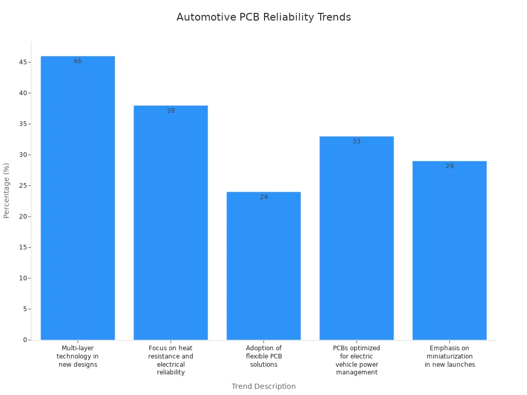
Watch for new ideas and rules. This helps your boards stay safe and work well in the future.
FAQ
What makes automotive PCBs different from regular PCBs?
Automotive PCBs face heat, shaking, and wet conditions. You must use tough materials and follow strict rules. These boards need to last longer and work in hard places.
How do you test automotive PCBs for reliability?
You use tests like thermal cycling, vibration, and burn-in. These tests show if your board can handle real car conditions.
Tip: Always check your boards with AOI and functional testing.
Why is thermal management important in automotive PCB design?
Heat can hurt parts and cause problems. You need to move heat away from hot spots. Good thermal management helps your board last longer and work better.
Which materials work best for automotive PCBs?
You should pick materials like polyimide, ceramic, or metal-core. These materials handle heat and stress well.
Polyimide works for high heat.
Metal-core helps with LEDs.
See Also
Essential Quality Control Measures for Heavy Copper PCB Assembly
Explore Cutting-Edge HDI PCB Prototyping Methods Now
Which PCB Design Best Addresses ATE Requirements?
Frequent PCB Design Issues and Their SMT Solutions
Comprehensive Guide to Heavy Copper Multilayer PCB Production
