Electrical Insulation Requirements for PCB Stators
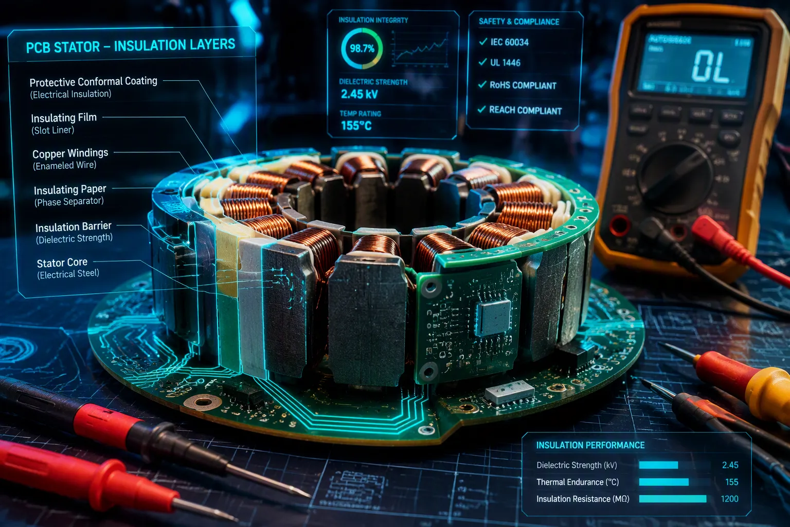
UL, NEMA, and IEC standards set the Electrical Insulation Requirements for a PCB stator. These standards focus on dielectric strength, thermal endurance, and partial discharge resistance. Engineers often have wrong ideas about insulation class. These wrong ideas lead them to guess stator life incorrectly. This problem is common when they compare a printed circuit board stator to a normal wound stator. One common mistake is treating a material rating as the same as a system rating. Another mistake ignores how manufacturing quality affects electrical insulation performance. So, what exactly are the Electrical Insulation Requirements for a PCB stator, and how do they differ from normal designs?
Key Takeaways
PCB stators must follow strict insulation rules for safety and reliability.
Each PCB layer should carry one phase to stop electrical shorts.
Building with no empty spaces gets rid of air pockets and helps heat escape better.
Insulation class by itself does not decide how long a stator will last; thermal margin and quality also matter.
PCB stators can take the place of traditional slot insulation in many uses.
Electrical Insulation Requirements for PCB Stators
Dielectric Strength, Partial Discharge, and UL 150°C Rating
A printed circuit board stator has to meet certain electrical insulation requirements, and dielectric strength is the first one. IPC-2221 sets the breakdown voltage based on conductor spacing and material thickness. Engineers use this standard to pick the right clearances for the operating voltage. The dielectric strength of the laminate decides how much voltage the insulation can block before it fails. Partial discharge inception voltage measures the point where corona starts inside the insulation. This threshold matters a lot for stators that run above 480 V. The UL 150°C material rating applies to the FR4 epoxy laminate substrate. That rating means the material can handle continuous operation at 150°C without losing its electrical insulation properties. Insulation strength stays good at that temperature when the laminate is processed the right way. To check these parameters, UL 1446 testing puts the insulation system through voltage endurance tests under controlled stress. These tests confirm the insulation system can take long-term voltage without breaking down. Another key factor is dielectric stress conditions, which happen when voltage builds up in small areas. Engineers design the layout to spread voltage evenly across the laminate. The quality of PCB insulation depends on void-free lamination and precise layer registration. With no voids, the insulation fights partial discharge more effectively. A well-built printed circuit board stator uses all these design elements to meet the electrical insulation requirements for its application.
Minimum Insulation Resistance and Layer Isolation
Insulation resistance is another key parameter. For low-voltage stators below 1 kV, the minimum insulation resistance is 5 MΩ. This value follows IEEE Std 43-2013.
IR = 5 MΩ — Most machines with random-wound stator coils, form wound coils rated below 1 kV, and DC armatures (minimum insulation resistance after 1 minute at 40°C).
Steady insulation resistance stops leakage currents that wear down performance over time. Checking this value during production helps ensure reliable operation. Layer isolation is just as important to prevent shorts. Each PCB layer should be used for a single phase, removing cross-phase copper traces. This construction avoids phase-to-phase faults and makes the insulation design simpler. The dielectric strength between layers depends on the prepreg thickness and copper spacing. Engineers figure out the required dielectric strength based on peak voltage and margin. For safety, the design usually includes a 20 % margin above the expected voltage. The insulation between layers must also handle mechanical stress from thermal expansion. The laminates used in PCB stator insulation are matched to the copper for minimal stress. This matching cuts crack formation and keeps insulation integrity over the stator life. Complete electrical insulation requirements for PCB stators include all these parameters. Meeting each requirement ensures the stator can run reliably under normal and fault conditions.
Understanding Motor Armature Insulation Classes
NEMA Class B, F, and H Temperature Ratings
NEMA groups motor armature insulation classes by the hottest temperature each system can handle for a long time. Class B insulation can work at 130°C. Class F can work at 155°C. Class H can work at 180°C. These temperatures apply to the hottest spot inside the winding, not the average motor frame temperature.
Insulation Class | Temperature Class |
|---|---|
B | 130°C |
F | 155°C |
H | 180°C |
PCB stator materials have a UL rating of 150°C. That number is close to Class F, but the two are not the same. The UL 150°C rating is for the laminate substrate only. A NEMA insulation class covers a full electrical insulation system. This system includes the conductor coating, the laminate, and the solder mask. Engineers who think the laminate rating can replace a Class F system miss this point. UL 1446 tests the whole insulation system, not just one material. The test checks that all parts work together at the rated temperature.
Common Myths About Class and Stator Life
A common myth says insulation class alone decides stator life. That idea is false. The insulation class only sets a temperature limit. Real life depends on how close the motor armature runs to that limit, how often it cycles, and its environment. A Class H system at its limit will fail faster than a Class B system running well below its rating. Thermal margin matters more than the class label. Moisture, vibration, and chemicals also shorten life no matter the class. Engineers should look at the whole motor armature design, not just the class on a datasheet.
Another myth says a higher class always means a higher price. In truth, a PCB stator with a 150°C UL rating may beat a regular Class H motor armature slot insulation in some uses. The void-free design of a PCB stator removes air gaps that hold heat. Better heat dissipation keeps the hot spot cooler, which extends life even at a lower class rating. The insulation class is just one of many factors. Operating temperature, thermal margins, and manufacturing quality all affect the result. Engineers who only look at the class number miss the full picture of stator reliability.
Design Factors for PCB Stator Insulation
Single Phase Layer Construction and Thermal Dissipation
A PCB stator gives each motor phase its own full layer. This setup removes copper traces that cross between phases. A fault between phases cannot happen because the paths never touch. The electrical insulation system becomes simpler and easier to predict. Dielectric strength between layers comes from the prepreg thickness and copper spacing. Designers figure out this strength from the peak voltage and add a 20% safety margin.
More surface area is another plus. PCB stators spread heat across the whole board. A normal wound motor traps heat inside the slot. The coil straight section and its end turns get the hottest. A PCB stator spreads that same heat over a wide flat surface. So, it needs less copper to carry the same current. Cooler windings protect the insulation from thermal aging. The PCB winding end turns sit flat against the laminate, so air can cool them directly.
Mechanical and Environmental Stress Considerations
Matching thermal expansion cuts mechanical stress. The laminate and copper layers expand at similar rates when heated. Mismatched expansion would pull on vias and traces. That pulling creates micro-cracks. Cracks become weak points for partial discharge. Void-free construction also stops air pockets. Air pockets trap heat and let corona start. A solid laminate keeps insulation intact over many thermal cycles.
Environmental factors matter too. Moisture can lower insulation resistance. PCB materials resist moisture better than paper slot insulation. Vibration can fatigue solder joints and cause layer separation. A flat, rigid PCB stator handles vibration better than a bundled coil. Engineers can specify conformal coating for humid or dusty environments. Coating adds an extra barrier without changing the board layout. Each design decision affects long-term reliability. The full system must match the operating environment, not just the temperature class.
Epoxy Coating Powder for Slot Insulation vs. PCB Materials
Motor Armature Slot Insulation in Conventional Stators
A regular motor armature depends on motor armature slot insulation to protect its windings. This motor armature slot insulation mixes paper liners with epoxy coating powders. Engineers choose epoxy coating powders based on voltage, temperature, and environment. Each epoxy coating powder gives a different thermal class. LINQSOL MCP-5000 epoxy coating powders give Class B (130°C) with a dielectric strength of 25 kV/mm. LINQSOL MCP-5260 epoxy coating powders give Class F (155°C) with a dielectric strength of 30 kV/mm.
Product | Thermal Insulation Class | Dielectric Strength |
|---|---|---|
LINQSOL MCP-5000 | Class B (130°C) | 25 kV/mm |
LINQSOL MCP-5260 | Class F (155°C) | 30 kV/mm |
The motor armature also uses epoxy coating powders for mechanical protection. After curing, these epoxy coating powders turn into a solid coating. Every epoxy coating powder carries its own rating. The motor insulation powder requirements change with operating conditions. Motors with higher voltage need thicker layers of epoxy coating powders. Motors with higher temperature need epoxy coating powders of a higher class. An insulating epoxy coating powder must stand up to moisture and vibration. Putting on epoxy coating powders takes careful control. Air trapped in epoxy coating powders lowers performance. Picking the right epoxy coating powders decides motor armature life. Manufacturers select epoxy coating powders based on what the application needs. A good epoxy coating powder keeps quality steady. The right epoxy coating powders make motor life longer. Every motor armature slot insulation has to handle these demands. Epoxy coating powders form the dielectric barrier for the motor armature. The motor armature slot insulation holds up when epoxy coating powders stay void-free. Many engineers call for epoxy coating powders in conventional stator builds. These epoxy coating powders meet tough motor armature requirements.
Void-Free Construction of PCB Stators
A pcb stator takes a different path for insulation. Laminate bonding and solder mask build a void-free dielectric layer. This design skips the air gaps that epoxy coating powders often leave. Heat moves better through the solid bond between layers. The pcb stators meet strict requirements without any extra coatings. The pcb stator uses the laminate as its main barrier. This method removes the need for paper and epoxy coating powders. Engineers pay attention to layer spacing instead of epoxy coating powders. For motor insulation powder requirements, a pcb stator gives a simpler option. The comparison shows pcb stators meet demanding insulation standards. Void-free construction gets rid of weak points found in conventional motor armature designs.
A pcb stator meets electrical insulation requirements through three main supports. First, the laminate has a 150°C UL rating. Second, each layer handles one phase, which stops cross-phase faults. Third, void-free construction removes air gaps that weaken electrical insulation. Together, these choices give reliable performance.
Engineers must keep one point in mind. The insulation class is only one factor. Thermal margins, operating temperature, and manufacturing quality affect stator life just as much. A lower class with a wide margin can outlast a higher class pushed to its limit.
Readers who want more guidance can download the detailed insulation design guide. They can also contact the company's application engineers for help with specific requirements.
FAQ
What is the minimum insulation resistance for a PCB stator?
IEEE Std 43-2013 sets the minimum at 5 MΩ for low-voltage machines. This value applies after one minute at 40°C. A steady reading at or above this level shows the insulation stops leakage currents during normal operation.
Does a UL 150°C laminate rating equal NEMA Class F?
No. The UL 150°C rating covers only the laminate substrate. NEMA Class F covers the whole system at 155°C, including conductor coating and solder mask. UL 1446 tests the complete system, so engineers cannot swap one rating for the other.
Which standard sets conductor spacing for breakdown voltage?
IPC-2221 sets breakdown voltage from conductor spacing and material thickness. Designers use it to pick clearances for the operating voltage. A 20% margin above expected voltage adds safety against partial discharge.
Why does each PCB layer carry only one phase?
One phase per layer removes copper traces that cross between phases. Phase-to-phase faults cannot happen when the paths never touch. This layout also makes the electrical insulation requirements simpler and dielectric behavior easier to predict.
Can a PCB stator replace epoxy coating powder slot insulation?
Yes, in many designs. Laminate bonding and solder mask create a void-free barrier without paper liners or epoxy coating powders. The solid bond improves heat flow and removes air gaps that weaken conventional slot insulation.
See Also
Key Safety Measures For Designing Printed Circuit Boards
Analyzing Thermal And Electrical Performance Of Aluminum Circuit Boards
Utilizing Panasonic Copper Clad Laminates In Circuit Board Production
Procedure For Creating Aluminum Based PCBs With Insulation Holes
Rigid PCB Fabrication Materials Processes And Quality Controls For Industry
