IPC Class 3 Standard: The Gold Standard for High-Reliability PCBs
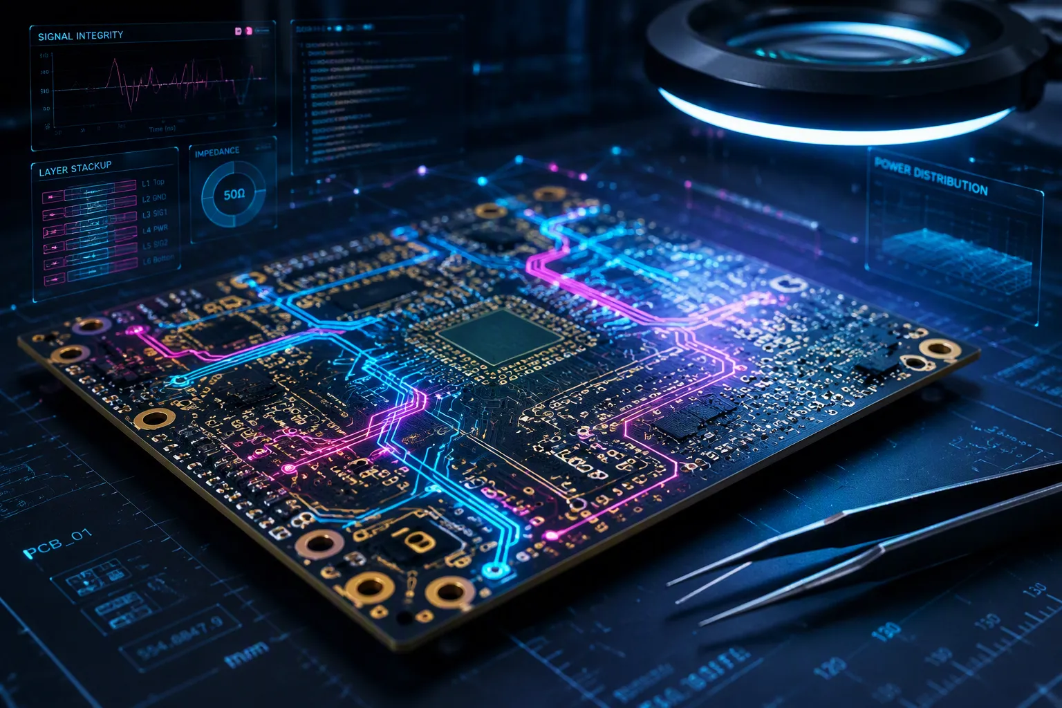
The IPC Class 3 standard is the top reliability level for printed circuit boards. It makes sure they work perfectly in key jobs where failure cannot happen. The IPC class rules split boards into three groups. Class 1 is for everyday products. Class 2 is for devices that run all the time. Class 3 needs the strictest quality. Class 3 rules are very strict.
This standard helps industries where safety and mission success are most important. An IPC Class 3 board stops terrible failures. Such failures risk injury, death, or big money loss. Manufacturers build these boards for the hardest jobs. These boards must work without any failure.
Key Takeaways
IPC Class 3 is the top reliability standard for PCBs, used in critical industries like aerospace, defense, and medical.
Class 3 boards follow stricter rules for plating thickness, annular rings, and voids to make sure they work in harsh conditions.
Class 3 needs more testing and paperwork than Class 2. This includes signed certificates and lot traceability.
Picking an IPC Class 3 manufacturer means you get top quality and dependability, which keeps people safe and protects your money.
For critical tasks, IPC Class 3 is the only safe choice to avoid failures and costly downtime.
Defining the IPC Class 3 Standard
What Is IPC Class 3?
The IPC Class 3 standard is the highest quality level for printed circuit boards. This class is for products that cannot fail. The boards must work all the time without any mistakes. The IPC class rules split electronics into three groups based on how they are used and how long they need to last.
IPC Class | Description | Life Span | Quality Requirement | Examples |
|---|---|---|---|---|
Class 1 | General electronics | Short | Cheap | Toys, flashlights |
Class 2 | Dedicated service electronics | Long | Good | Laptops, microwaves |
Class 3 | High-reliability electronics | Very long | Fail-proof | Aerospace, military, and medical applications |
Class 1 is for basic consumer devices. Class 2 is for general industrial products that need a long life. Class 3 electronics are for very important jobs. These products must keep working in tough conditions. They often face big temperature changes, strong shaking, and high moisture.
Class 3: High-Reliability Electronics — This class is for products that must always work when needed. Downtime is not allowed. Examples include life support systems, flight control systems, and military equipment.
The IPC Class 3 standard makes every part of production tougher. Solder joints, cleanliness, part alignment, and lead trimming all have stricter rules. A pacemaker or a military radar system must work well for years without any hidden failures. This reliability needs careful focus at every step.
IPC Standards for Class 3
Several IPC standards guide Class 3 production. The most important ones are IPC-A-610 for assemblies and IPC-6012 for rigid PCBs. IPC-A-600 sets the rules for checking quality. Together, these standards define good workmanship.
IPC-6012 covers rigid PCB types. This includes single-sided, double-sided, multilayer, and HDI boards. The standard sets rules for board size, materials, copper, trace width, plating, and surface finish. Industry add-ons add more rules. IPC-6012EA is for automotive PCBs with better vibration resistance. IPC-6012ES is for space and military uses. IPC-6012EM is for medical PCBs with tiny features.
IPC-A-600 sets acceptance rules for bare boards. Class 3 needs a minimum annular ring of 0.002 inches (0.05 mm). Minimum copper plating thickness in holes is 25 µm. Layer spacing must be at least 0.08 mm. Microvia voids cannot be more than 10% of the hole's diameter. These rules ensure long-term reliability in hard conditions.
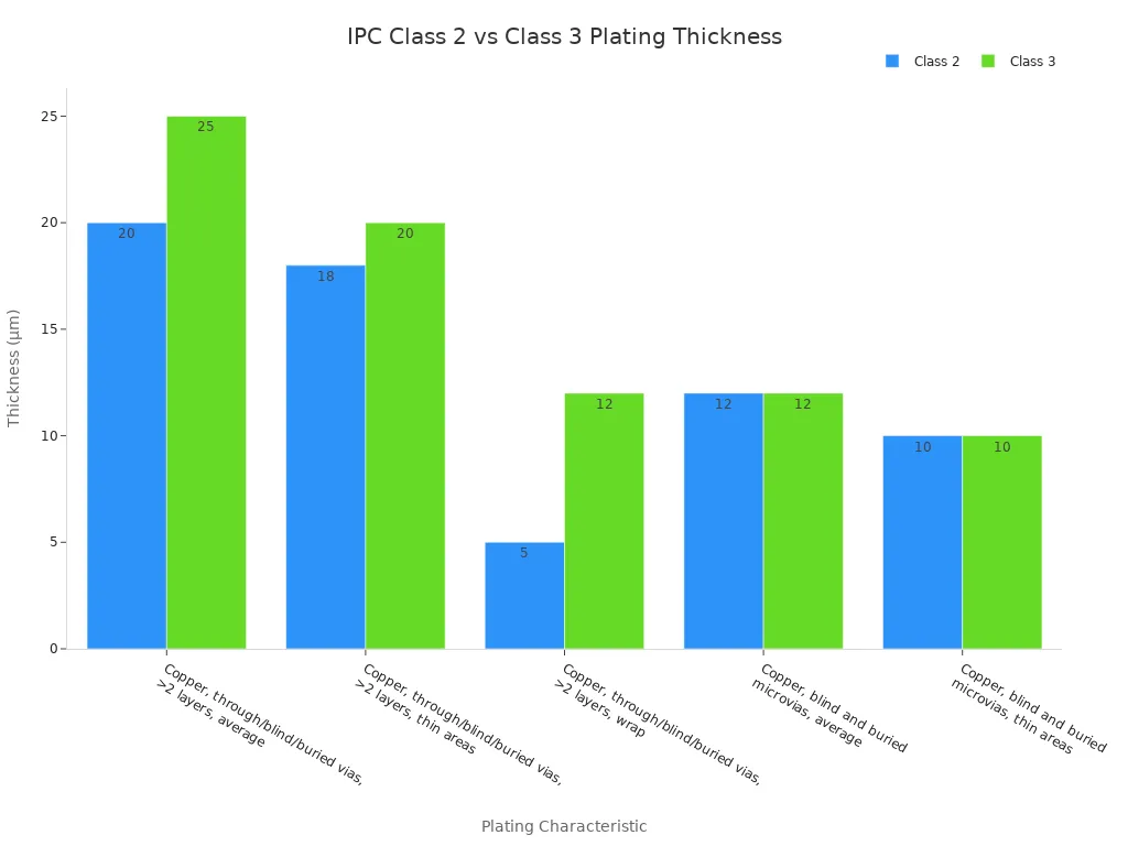
Class 3 needs stricter checks, tests, and paperwork than Class 2. Through-hole barrel fill must be 75% for Class 3, but only 50% for Class 2. Class 2 allows one void in 5% of holes. Class 3 allows no voids. Plating thickness also differs: 0.8 mil for Class 2, 1 mil for Class 3. Tear-dropped via pads are required for Class 3 boards to prevent hole separation.
Paperwork rules also get tougher. Class 3 needs signed certificates, first-article reports, and inspection results tied to production lots. X-ray images may be needed for hidden joint risks. Material and part tracking must follow contract rules. These steps make sure every PCB meets the top standard for high-reliability use.
IPC Class 3 in Harsh Environments
Mission-Critical Performance
Class 3 boards must keep working without any breaks in the hardest conditions. Their performance must be steady, predictable, and perfect. These boards face extreme temperature changes, strong shaking, sudden impacts, wetness, dust, and chemicals. They also need protection from electromagnetic interference.
To work well at high heat and high altitude, these boards use special materials. Examples are polyimide laminates, PTFE, and ceramic-filled substrates. These materials stop layers from peeling, keep their shape, and lower signal loss at high frequencies. Radiation-hardened materials guard satellites and space vehicles against cosmic rays and solar flares. Military PCBs need shielding layers, ground planes, and controlled impedance with differential signal routing.
Common causes of failure in tough applications include moisture getting in, dirt, repeated heating and cooling, and sudden impacts. Bad solder joints also cause failures. These problems come from not enough solder, wrong reflow temperatures, dirt during assembly, and parts that are not lined up correctly. Weak solder joints can crack over time from shaking or temperature changes. The IPC Class 3 standard lowers these risks by having stricter rules for solder joints, cleanliness, and part alignment.
Cost of Failure vs. Cost of Quality
Class 3 is for products that cannot fail. A broken pacemaker or flight control system can cause injury, death, or huge money loss. Spending on quality at the start stops these terrible outcomes.
The cost of failure is much higher than the cost of quality. One recall or mission failure can cost millions and hurt reputations. Class 3 makers spend on advanced testing and tracking to make sure every PCB meets the top standard. This focus on reliability and strength protects people's safety and money. For industries where stopping is not okay, the IPC Class 3 standard is the only choice.
Class 2 vs. Class 3
Key Technical Differences
The main difference between Class 2 and Class 3 is how much extra safety a board has. Class 2 boards work fine in normal use. Class 3 boards must survive the worst conditions without any hidden defects. The IPC class definitions purposely keep these two levels apart. Class 2 allows some breakout on pads. Class 3 does not allow it on outer layers. This one rule changes how designers pick pad sizes, drill sizes, and trace routes.
The width of the annular ring affects how well solder works, how electricity flows, and how sturdy the board is. A ring that is too small leads to poor soldering and weak connections. The circuit might then fail sometimes or stop working completely. For Class 3, the outer layer ring must be at least 2 mil (0.050 mm) from the via wall plating to the pad edge. The inner layer ring must be at least 1 mil (0.025 mm) from the drilled hole to the pad edge. Class 2 allows a 90-degree breakout instead. Teardrop shapes at trace-to-via connections add strength when the board heats and cools or shakes. So Class 3 electronics use larger pads and tighter drill control.
The thickness of the plating also differs. Class 3 requires at least 25 μm average copper in through, blind, and buried vias on boards with more than two layers. Class 2 only needs 20 μm. Thin areas go down to 20 μm for Class 3 and 18 μm for Class 2. Wrap plating increases from 5 μm to 12 μm. Microvias stay the same at 12 μm average for both classes. Barrel fill makes another difference. Class 3 needs 75% fill, while Class 2 needs 50%.
For Class 3, at least 75% of the hole must be filled with plating. This ensures the board is strong and works well.
The rules for voids show the biggest difference. Class 3 allows no voids in any via hole. Class 2 allows one void per hole, but no more than 5% of holes can have voids, and each void must be under 5% of the hole length. These stricter rules remove weak spots that can turn into cracks after many years of use.
Comparison of Specifications
The table below summarizes the main differences across annular ring, plating, inspection, and documentation.
Requirement | IPC Class 2 | IPC Class 3 |
|---|---|---|
External annular ring | Breakout allowed up to 90° | Minimum 2 mil (0.050 mm) |
Internal annular ring | Tangency permitted | Minimum 1 mil (0.025 mm) |
Copper plating, vias, average | 20 μm min. | 25 μm min. |
Through-hole solder fill | 50% | 75% |
Via voids | One per hole, max 5% of holes | None permitted |
Ionic contamination | ≤ 1.56 μg NaCl/cm² | ≤ 0.78 μg NaCl/cm² |
Visual inspection magnification | 3× – 10× | 10× – 30× |
AOI defect detection threshold | up to 0.2 mm | up to 0.1 mm |
Inspection and documentation get stricter along with the physical rules. Class 3 inspection uses 10× to 30× magnification, while Class 2 uses 3× to 10×. Automated optical inspection finds defects as small as 0.1 mm for Class 3 and 0.2 mm for Class 2. Documentation for Class 3 includes signed certificates, first-article reports, and lot-level traceability. These standards lead to higher reliability for products that cannot stop working. A medical implant or satellite controller built to Class 3 has extra safety at every joint, every pad, and every plated hole. That extra safety is what keeps pcbs running for decades in the field.
Industries Requiring IPC Class 3
Aerospace, Defense, and Medical
Aerospace and defense programs almost always require IPC Class 3. Flight hardware, satellite systems, launch vehicle electronics, and avionics need this level. Weapons systems, C4ISR electronics, tactical communications, and MIL‑STD programs also use Class 3. Many customers specifically ask for IPC-6012 Class 3A plus AS9100 standards for flight-critical avionics. These PCBs survive very hot and cold temperatures, strong shaking, and radiation.
Medical devices follow similar rules. The FDA groups devices by risk. Class III medical devices need Premarket Approval with clinical data. ISO 13485:2016 controls the quality management system. IPC-A-610 Class 3 is the lowest level for implantable devices. Manufacturing happens in cleanrooms to cut down on tiny particles. Process validation follows IQ, OQ, and PQ steps. Environmental stress screening includes temperature changes and shaking. Burn-in testing at high heat finds early failures. Functional testing uses in-circuit tests and boundary scan analysis. EMC testing checks that the device does not interfere with hospital equipment. Biocompatibility per ISO 10993 is needed for devices that touch the body. FDA 21 CFR Part 820 controls production steps. These rules make IPC Class 3 the default for important medical uses.
Automotive and Industrial Control
Automotive under-hood electronics work from -40°C to 125°C. Vibration loads follow ISO 16750-3 with random profiles from 20 to 2000 Hz. Field DPPM targets for Tier-1 safety systems stay at or below 10 DPPM. These numbers are many times tighter than commercial electronics. AEC-Q-grade parts are tested for automotive stress. Conformal coating protects against moisture, salt spray, and condensation during temperature changes. Class 3 sets stricter rules for solder joints, annular rings, and hole fill. Inspection is closer to full checking rather than light sampling. Rework is very limited. The IPC class definitions separate these boards from consumer electronics. Most automotive PCBA field failures come from environmental stress, not design mistakes.
Industrial control systems also gain from this level. Power plants, oil exploration equipment, robotics, and PLC controllers run without stopping. PCB defects stop production lines and cause costly downtime. Certified assembly improves electrical stability and lowers failures. Better harsh-environment reliability stops failures in very hot or cold, shaking, or radiation. Lower total cost of ownership offsets higher upfront costs through less maintenance and longer product life. High-reliability electronics like Class 3 boards make sure they run without stopping in tough places. For these industries, the quality and durability of Class 3 electronics are needed for mission-critical work.
Benefits of an IPC Class 3 Manufacturer for High-Reliability PCBs
Expertise and Quality Control
An IPC Class 3 certified maker knows a lot about building PCBs. Workers and inspectors learn the toughest IPC-A-610 rules. The factory must track parts, repeat steps, and check quality deeply. Getting certified means outside experts check the work, customers visit, and the process is always watched. These steps set true Class 3 shops apart from basic ones.
Tight process rules guide all work. Stricter limits make every board more exact in size. Better material choices help the board last in rough conditions. No mistakes are allowed in key spots, so workers think without flaws. Microscope checks, slice tests, and heat cycles find hidden problems before shipping. Statistics track error rates, with goals near zero for Class 3 builds. Any problem gets fixed right away. This strong quality control keeps high‑reliability electronics from failing in the field.
Advanced Testing and Traceability
Full testing checks each PCB against the top standard. Slice checks, heat stress, and electrical tests prove reliability. A maker might run inside tests but not give the full report pack, so buyers should say which records they need.
Traceability links each board to every step of its making. Records show material lots, board suppliers, copper batches, date codes, process settings, check results, and worker certifications. A special number or UID goes on each board, even when many are made together. This number connects materials, steps, checks, and tests to that board. Aerospace makers often use IPC-1782 to track electronics under AS9100.
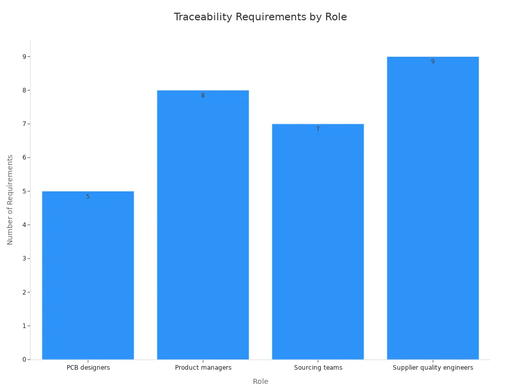
These records let managers find affected lots, learn why problems happened, and stop them from coming back. For high‑reliability PCBs, this much paperwork is not a choice. It is the base of trust.
The IPC Class 3 standard is more than a certification. It is a commitment to uncompromising quality and reliability at every production step. For industries where failure is not an option, an IPC Class 3 certified manufacturer is the only safe choice. These makers deliver the long-term success and safety that critical programs demand.
Every solder joint, pad, and plated hole meets stricter rules. This discipline protects lives and investments alike. No other benchmark matches this level of rigor for high-reliability PCBs. This standard remains the gold standard, and it will stay that way for years to come. That promise keeps planes flying, patients safe, and factories running.
FAQ
What is the highest PCB standard?
The IPC Class 3 standard has the strictest rules. It needs thick plating, no voids, and strong annular rings. This standard makes sure products work without failure.
How does Class 3 differ from Class 2?
Class 3 needs thicker copper plating. It needs bigger annular rings. Voids are not allowed. IPC-A-610 and IPC-6012 set these rules. Class 2 allows some breakout and voids.
Which industries require this standard?
Aerospace, defense, and medical industries use Class 3. Car safety systems also use it. These sectors need high reliability. Strict quality control stops failures.
What testing is required for Class 3 boards?
Thermal cycling checks board strength. Microsection analysis checks plating. X-ray inspection spots hidden flaws. IPC standards require these tests. Every board must pass them.
See Also
Understanding The Basics Of High-Speed Printed Circuit Boards
A Complete Guide To Manufacturing Heavy Copper Multilayer PCBs
Rigid PCB Production: Materials, Processes, And Quality Standards For Industry
Mastering Quality Control Techniques In Printed Circuit Board Manufacturing
Seven Essential Quality Control Steps For High Current Heavy Copper PCB Assembly
