High TG PCB Manufacturing Process Requirements
High tg pcb manufacturing process requirements are about picking materials and ways that can handle high heat. These materials and methods must not lose their performance. Tg means glass transition temperature. It is the point where PCB materials go from hard to bendy. Many industries need custom high tg pcb fabrication. This helps make sure things work well in tough places. For example, aerospace, automotive, military, medical, telecommunications, and industrial companies use high tg pcb in important systems. The table below shows main uses in these areas.
Industry | Primary Applications |
|---|---|
Aerospace and Aviation | Flight control systems, engine controls, navigation electronics |
Automotive | Engine control modules, ABS, sensors, infotainment systems |
Military and Defense | Mission-critical systems needing to work with shock, vibration, and heat |
Medical | Imaging systems, monitoring devices, diagnostic equipment |
Telecommunications | Base stations and networking hardware that keep signals strong |
Industrial | Process control and automation systems in hot factories |
Manufacturing needs are not the same as regular pcb manufacturing. High tg pcb fabrication service must use materials that can take more heat. They also need tighter process controls.
Key Takeaways
High TG PCBs can handle heat over 170°C. This makes them good for tough jobs in aerospace and cars.
Picking the right materials is very important. High TG materials stop problems like layers coming apart and tiny cracks from heat.
The lamination process needs careful control of heat and pressure. This helps the PCB stick together well and work right.
Cleaning after drilling is very important. It keeps the PCB strong and helps copper stick better.
Managing heat during making stops the board from bending. It also keeps the board steady when the temperature changes.
Testing often is needed, like checking heat cycles and electrical parts. This makes sure high TG PCBs are good quality.
Engineers and makers should work together when designing. This helps find problems early and saves time and money.
Having industry certificates shows care for quality and safety in making high TG PCBs.
High TG PCB Overview
What Is High TG PCB
A high tg pcb is made to handle more heat than regular boards. Tg means glass transition temperature. This is the point when the board goes from hard to soft. High tg pcb materials have a tg over 170°C. Standard FR-4 boards have a tg between 130°C and 140°C. The table below shows the difference:
Type of PCB | Glass Transition Temperature (Tg) |
|---|---|
> 170°C | |
Standard FR-4 PCB | 130-140°C |
Manufacturers use high tg pcb materials for jobs that need extra heat resistance. These boards work well where regular boards would not.
Importance Of Tg In PCB
The tg value is very important for how printed circuit boards work. Tg is the temperature where the resin inside the board changes from stiff to flexible. Below tg, the board stays strong and stable. Above tg, the resin grows fast, mostly up and down. This can put stress on metal parts inside the board. Problems like barrel cracking, delamination, and pad cratering can happen if the board gets too hot for too long.
High tg pcb materials keep the board from growing too much at high temperatures. This helps stop common failures, such as:
Delamination of laminate layers
Pad cratering
Micro-cracking in via barrels
Thermal failure from exceeding tg
A high tg pcb keeps its shape and works well during heating and cooling. This is very important for advanced electronics.
Applications Of High TG PCB
Many industries use high tg pcb technology for tough jobs. These boards help devices work in hot places or with quick temperature changes. Common uses include:
Automotive electronics like engine control units and infotainment systems
Aerospace and defense systems such as avionics and satellites
Industrial equipment that runs all the time and gets hot
High-power electronics like power converters and inverters
LED lighting modules that need good heat control
Telecommunications equipment for steady network performance
Oil and gas electronics used in rough field conditions
Medical devices that must work in different clinical temperatures
Consumer electronics like laptops and smartphones
Renewable energy systems such as solar inverters
Electronic testing tools for checking at different temperatures
High-performance computing in servers and data centers
These examples show how a high tg pcb helps devices work well in important systems. Picking the right tg value stops failures and makes electronics last longer.
High TG PCB Materials
Material Selection Criteria
Picking the right materials for high tg printed circuit boards is important. It helps the board work well in tough places. Engineers want materials that can take a lot of heat. They also need to handle stress and changes in temperature.
Tg Value Requirements
Tg, or glass transition temperature, is the key thing to check. Materials with higher tg do not get soft or change shape when hot. The industry puts materials into three groups by tg:
Standard Tg sheets: above 130°C
Medium Tg materials: around 150°C
High tg materials: exceed 170°C
The table below shows the lowest tg for each PCB material:
Type of PCB Material | Minimum Tg Value (°C) |
|---|---|
Standard FR4 | 130 - 140 |
Mid-Tg FR4 | 150 - 165 |
High-Tg FR4 | 170 - 200 |
For example, if a device gets as hot as 125°C, the material’s tg should be at least 155°C. High tg materials usually start at 170°C and can go up to 200°C or more.
High-Temperature FR-4 And Fiberglass
High-temperature FR-4 and fiberglass are used a lot for high tg printed circuit boards. High-Tg FR-4 works great in cars and factories where things get hot often. Polyimide and Rogers laminates are used for special jobs. They have even higher tg values.
Material Type | Tg (°C) |
|---|---|
FR4 | 130 - 180 |
Polyimide | 175 - 180 |
Rogers Laminates | 280 |
Critical Material Properties
High tg materials must meet strict rules for heat and strength. These things help the board not break when it is working.
Thermal Stability
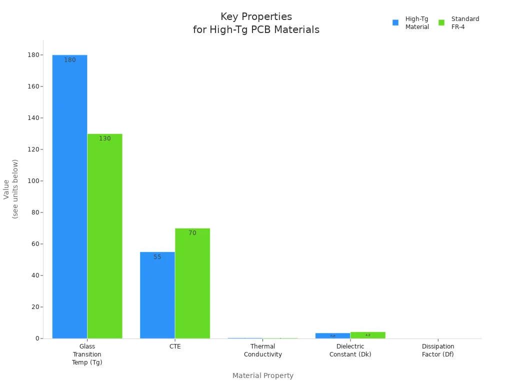
Thermal stability means the material stays strong and keeps its shape when hot. High tg materials like ITEQ IT-180A (tg 180°C) and Arlon 85N (tg 250°C) stay hard even at high temperatures. They also have a lower coefficient of thermal expansion (CTE), usually 50-60 ppm/°C. Standard FR-4 has a CTE of 70 ppm/°C. A lower CTE means less stress on vias and solder joints.
Property | Description |
|---|---|
Glass Transition Temperature (Tg) | High-Tg materials stay hard under heat. |
Coefficient of Thermal Expansion (CTE) | Lower CTE means less stress on vias. |
Thermal Conductivity | High-Tg materials help move heat away. |
Dielectric Constant (Dk) | High-Tg materials keep Dk steady when hot. |
Dissipation Factor (Df) | High-Tg materials have lower Df, so there is less signal loss. |
Mechanical Strength
Mechanical strength is also very important for high tg printed circuit boards. High tg materials do not crack, peel, or bend easily during making or use. They keep the board steady, even if it shakes or gets hit. This strength helps the board last longer and work well in hard places.
Tip: Always pick a tg value that is higher than the hottest temperature the board will face. This helps stop problems and makes the board last longer.
PCB Manufacturing Process Steps
Lamination Process
The lamination process is the first step in making high tg pcb. Engineers stack layers of high tg materials. They press these layers together under careful conditions. This step helps the board handle high heat and stay strong.
Temperature And Pressure Control
Temperature and pressure are very important in lamination. Operators must use exact settings for good bonding. High tg pcb materials need higher temperatures and pressures than regular boards.
Parameter | Standard FR-4 | High-Tg FR-4 |
|---|---|---|
Peak temp | 175-185°C | 185-200°C |
Ramp rate | 2-3°C/min | 2-3°C/min |
Dwell time | 45-60 min | 60-90 min |
Target pressure | 250-350 psi | 300-400 psi |
Operators watch these numbers closely. Higher heat and pressure help the resin flow and harden. This makes the board work well in hot places.
Curing Cycle For High TG PCB
The curing cycle makes sure the resin gets the right tg value. Manufacturers follow special steps to make the board strong:
Lamination temperatures often reach 185–195°C.
Pressure bands range from 250–450 psi.
Moisture pre-bake happens at 120–150°C for 2–6 hours.
Some high tg materials need lamination near 200°C to cure fully.
Always check the manufacturer's datasheet for exact settings.
These steps help the board get the right tg and stop defects. Good curing also makes the board stronger and more stable in heat.
Drilling And Hole Preparation
Drilling and hole preparation make paths for electricity. This step must be done carefully for high tg pcb reliability.
Drill Aspect Ratio And Annular Ring
Drill aspect ratio and annular ring size affect how strong the board is. Engineers follow these rules:
Drill aspect ratios should stay below 10:1 for safe drilling.
Minimum annular ring sizes are 4 mil for mechanical drills and 3 mil for laser drills.
Annular rings of 4-5 mil help avoid problems.
Small rings can cause parts to break off or not attach well.
Tiny rings increase defects and make the board weaker.
If rings are too small, the board cannot carry enough current.
Tip: Engineers should always use enough annular ring size and the right drill aspect ratio. This stops failures from heat changes and keeps connections strong.
Cleaning Protocols
Cleaning after drilling is very important for high tg pcb. Operators follow these steps:
Keep surfaces clean so drills do not wander.
Use plasma etching or special cleaning after drilling.
Remove resin smear and debris so copper sticks well.
Other good practices include:
Set drilling to make less heat.
Use desmear with potassium permanganate or plasma etch.
Try lower spindle speeds for resin-rich materials.
Use entry and backup materials to stop burrs.
Use mechanical deburring with orbital scrubbers.
Increase spindle speed for cleaner cuts and change drill bits often.
Good cleaning helps copper stick and stops voids. This step makes the board last longer and work well.
Plating And Metallization
Plating and metallization make paths for electricity in the board. This step must handle high heat and keep copper stuck well.
Copper Deposition
Copper deposition uses electroplating, electroless plating, or direct metallization. These ways make even copper layers with the right thickness. The process helps copper stick to the board and other layers. Factories check bath chemistry and copper sulfate levels for good results.
The usual steps are:
Start with edge masking using photoresist or dry film.
Electrolytic copper plating comes next in panel or pattern order.
Etch after plating to remove extra copper.
Add surface finishes quickly to protect copper.
Electroless copper must cover the dielectric and connect inner layers well. Good copper sticking in holes and layers is needed for strong boards.
Adhesion Challenges
Adhesion problems can happen during plating in high tg pcb. PTFE’s surface can push away masks and cause sticking issues. Drilling makes heat and debris that block plating.
Ways to fix this include:
Plasma treatment adds groups to help things stick better.
Chemical etching with sodium naphthalenide makes the surface rough for better grip.
Add masks right after etching to use fresh oxide layers.
Use slow ramp rates in curing to stop heat mismatch.
Process controls help keep things stuck:
Add masks soon after etching.
Use special formulas to help sticking.
Check sticking with tape tests and heat cycles.
Industry standards help check quality:
IPC-6018 gives rules for high-frequency boards.
IPC-A-600 helps with visual checks for sticking.
Good sticking makes the board handle heat and work well for a long time.
Imaging And Etching
Imaging and etching make the circuit shapes on high TG PCBs. These steps need careful work to keep the patterns correct and strong.
Photoresist Application
Manufacturers put a photoresist layer on the PCB. This layer keeps some parts safe from etching. They pick dry film or liquid photoresist based on how hard the board is to make. Dry film photoresist gives sharper edges and sticks well to high TG materials. Workers shine ultraviolet light on the board through a mask. The light makes the photoresist hard in the right spots. After this, they wash away the soft photoresist that was not hit by light.
Key things for high TG PCB photoresist:
Dry film photoresist sticks well and makes sharp lines.
The process must not have bubbles or empty spots, or there will be problems.
Workers set the light time and strength to fit the material.
High TG boards need more light and careful washing to stop undercutting.
Note: Putting on photoresist the right way keeps circuit lines clean and stops bad etching.
Etching Adjustments
Etching takes away copper from places not covered by photoresist. High TG PCBs need special changes because their materials fight off heat and chemicals. Makers use stronger etchants or let the etching go longer. They watch the process closely so they do not take off too much or too little copper.
Common etching changes for high TG PCBs:
Use stronger etchant for tough materials.
Make etching last longer to get all the copper off.
Keep the temperature just right during etching.
Check boards after etching for smooth edges and the right line size.
Tip: Changing etching steps helps make good circuit shapes and stops problems in high TG PCBs.
Solder Mask And Surface Finish
Solder mask and surface finish keep the PCB safe and help it work better. High TG PCBs need materials that can take high heat and many hot-cold cycles.
Solder Mask Compatibility
Makers pick solder mask materials that stay strong in heat. Dry film solder masks with a Tg over 140°C work well for high TG PCBs. These masks can take heat over 300°C for a short time, which is needed for lead-free soldering.
Good solder mask features:
Stays strong in high heat for soldering.
Sticks well to the PCB.
Does not peel after many hot-cold cycles.
Fights off strong cleaning chemicals and flux.
Is thick enough (0.8 to 1.2 mils) to protect the board.
Alert: Using the right solder mask stops layers from coming apart and keeps the board safe when putting parts on.
Surface Finish Options
Surface finishes cover bare copper and help with soldering. High TG PCBs often use finishes that can take heat and keep signals clear.
Popular surface finish choices:
ENIG (Electroless Nickel Immersion Gold): Stays flat and strong in heat.
OSP (Organic Solderability Preservative): Protects for a short time and is good for quick builds.
Immersion Silver: Lets electricity flow well and solders easily.
HASL (Hot Air Solder Leveling): Good for boards with big pads and not tiny parts.
Surface Finish | Thermal Performance | Solderability | Typical Use Cases |
|---|---|---|---|
ENIG | High | Excellent | High-density, high TG PCBs |
OSP | Moderate | Good | Short-term, cost-sensitive builds |
Immersion Silver | High | Excellent | RF, high-speed applications |
HASL | Moderate | Good | Standard, less dense PCBs |
Tip: Pick a surface finish that fits the board’s heat and signal needs.
Thermal Management In Process
Thermal management stops the board from bending, breaking, or failing in high TG PCBs. Makers use different ways to control heat while making the board.
Pre-Bake And Moisture Removal
Pre-bake steps take water out of PCB materials. Workers heat boards at set temperatures before adding parts. This stops bubbles and layers from coming apart during soldering.
Pre-bake and moisture removal help by:
Drying out water, so there are fewer problems.
Letting out stress and keeping the board the right size.
Making soldering better by giving dry surfaces.
Stopping bad stuff from building up, so the board lasts longer.
Keeping the board flat and lined up for tight designs.
Note: Pre-bake is needed for high TG PCBs to work well.
Controlled Cooling
Controlled cooling keeps the board strong after hot steps. Makers cool boards slowly so they do not crack. This keeps the layers stuck together.
Good cooling ideas:
Pick high TG materials with Tg 20–30°C above the hottest use.
Use thicker copper to spread heat better.
Put thermal vias under hot parts to move heat away.
Spread out hot parts to stop hot spots.
Run heat tests early to find problems.
Technique | Description |
|---|---|
Material selection | High-Tg materials stay strong in heat. |
Increased copper thickness | Thicker copper spreads heat and lowers stress. |
Via-in-pad technology | Vias under parts move heat and keep signals clear. |
Tip: Good heat control during making keeps the board flat and strong, even in hard jobs.
Process Requirements And Quality Control
Thermal Stress Testing
Thermal reliability testing is very important for high tg pcb quality. Makers use different tests to make sure each board can survive tough places. The most common test is thermal shock testing. This test quickly changes the board’s temperature, sometimes by more than 15°C each minute. For example, a board might go from -40°C to +160°C very fast. These quick changes can cause problems like via cracking or delamination because materials expand differently. Burn-in testing is also important. In this test, the board faces high heat and electricity for a long time. This helps find hidden problems before the board leaves the factory. Coefficient of thermal expansion (CTE) testing checks how much the board grows or shrinks with heat. If the CTE is too different, it can cause cracks in plated through holes or make layers come apart.
IPC Standards
Industry standards help guide every step of thermal testing. IPC-A-600 gives rules for how the board should look, like checking for pits or scratches. IPC-6012 checks the board’s electrical, thermal, and mechanical properties. IPC-A-610 covers how the board is put together, including soldering and how clean it is. IPC-2221 gives tips for layout and picking materials. These standards make sure each high tg pcb meets strict quality rules.
Thermal Cycling
Thermal cycling tests how well a board handles heating and cooling over and over. This test can show weak spots in solder joints or vias. Solder joints can get tired after many cycles, which can cause tiny cracks or open circuits. Delamination and part failure can also happen from repeated stress. Makers use these tests to make sure the tg value is high enough for how the board will be used.
Electrical Testing
Electrical testing checks if the board works the way it should. Insulation resistance and signal integrity are two main things to check.
Insulation Resistance
Insulation resistance testing puts DC voltage between conductors to see how well the board stops current leaks. This test is very important for boards with many layers and high voltage. Dielectric withstanding voltage (Hi-Pot) testing uses even higher voltage to push the insulation system. This step makes sure the board is safe in strange situations and helps stop short circuits or fire.
Signal Integrity
Signal integrity testing checks if the board can carry signals without losing them or getting mixed up. Impedance testing uses tools like network analyzers or time-domain reflectometers. These tests make sure the lines for signals meet the design needs. Good signal integrity means the board can handle fast data and high-frequency signals without mistakes.
Mechanical And Environmental Testing
Mechanical and environmental tests show how strong and tough the board is. Flexural strength and chemical resistance are important for high tg pcb reliability.
Flexural Strength
Flexural strength testing bends the board to see how much force it can take before breaking. This test helps make sure the tg material keeps the board steady under stress. Makers also check for bow and twist, keeping these under 0.75% to meet quality rules.
Chemical Resistance
Chemical resistance testing puts the board in strong chemicals and high humidity. Polyimide materials are usually best for chemical resistance, then LCP, PEN, and PET. Damp heat aging tests check how well the board lasts after 1,000 hours at 85°C and 85% humidity. These tests make sure the tg value and material choice protect the board in hard places.
Tip: Makers use controlled bake-out, plasma desmear, and UV-curable solder masks to make boards more reliable. Every step in the process tries to meet strict quality rules and give a board that lasts.
Inspection And Certification
Inspection and certification are very important in making high TG PCBs. These steps make sure every board is safe and works well. Manufacturers use special tools to check each board. They also follow rules set by the industry. This helps make sure the boards are strong and ready for important jobs.
AOI
Automated Optical Inspection, or AOI, is a main way to check high TG PCBs. AOI machines use cameras and computer programs to look at each board. They find problems like solder bridges, missing parts, and pieces that are not in the right place. Workers set up AOI machines to look for tiny mistakes. These mistakes can cause problems, especially when boards get hot.
AOI helps companies find problems early. It checks for things like:
Scratches or pits on the surface
Parts put in the wrong spot
Solder joints that are not good
Broken lines or missing pads
AOI machines work fast and do not make many mistakes. They help people find problems quickly. When AOI finds a problem, workers look at the board. They decide if it should be fixed or thrown away. This step keeps high TG PCBs safe for use in planes, cars, and medical tools.
AOI helps catch problems before boards go to customers. It makes sure boards are made the same way every time and helps stop failures.
Industry Certifications
Manufacturers must follow strict rules to make high TG PCBs for important uses. These rules are called certifications. Certifications show that a company cares about quality, safety, and the environment. Each one has its own rules and checks different parts of making PCBs.
The most common certifications are:
Certification | Description |
|---|---|
ISO 9001 | International standard for quality management. |
IATF 16949 | Quality management standard for automotive sector. |
ISO 13485 | Quality management for medical devices. |
QC 080000 | Management system for hazardous substances. |
ISO 14001 | Environmental management system. |
ISO 50001 | Energy management system. |
UL Certificates | Safety certification for products in the US and Canada. |
RoHS Compliance | Restriction of hazardous substances in electrical and electronic equipment. |
Manufacturers must pass checks and keep good records to keep these certifications. For example, ISO 9001 means companies must write down how they do things and try to get better. IATF 16949 is for car parts, and ISO 13485 is for medical tools. UL checks if products are safe in the US and Canada. RoHS makes sure boards do not have dangerous stuff, which keeps people and nature safe.
Certification helps customers and inspectors trust the company. It shows the company can make high TG PCBs that are safe and work well in real life.
Challenges And Best Practices
Material Handling
Handling materials for advanced circuit boards is tricky. Some laminates can soak up water from the air. This can cause problems when making the boards. Cleanrooms help keep dirt and dust away. This stops changes in how the board works. Baking and storing materials in nitrogen keep them dry and steady. ESD protection is also important. It keeps the materials safe from static electricity.
Challenge | Solution |
|---|---|
Moisture absorption in low-Dk laminates | Baking and nitrogen storage |
Altered Df causing delamination during fabrication | ESD protection and cleanroom protocols |
Contamination exacerbating losses | Implementing cleanroom protocols |
Tip: Storing and handling materials the right way stops delamination and signal loss. Clean rooms and keeping things dry help the board keep its tg and work well.
Process Adaptations
Switching to advanced materials means changing how things are done. Workers slow down drilling to make tools last longer. Lamination uses more heat and pressure in several steps. Plasma cleaning is used instead of old cleaning ways. This gets the surface ready for the next steps. Solder mask uses special formulas that need higher heat to cure.
Process Step | Standard FR4 | High Tg Adaptation |
|---|---|---|
Drilling | 45K RPM | 40K RPM (reduced tool wear) |
Lamination | 180°C @ 300psi | 200°C @ 500psi multi-stage |
Desmear | Permanganate treatment | Plasma cleaning required |
Soldermask | LPI 150°C cure | High-stability LPI 170°C+ |
Makers also do these things:
Use higher heat and longer pressing for lamination
Watch the temperature closely during each step
Use vacuum lamination to stop air bubbles
Clean copper better before plating
Change plating chemicals for deep holes
Note: These changes help the board meet tough rules for working well and lasting long.
Cost And Lead Time
Making advanced boards costs more than regular ones. Special materials like polyimide and Rogers are more expensive. Adding more copper layers makes the price go up by 10-20% each time. Boards with many layers need more steps, which takes more time and money.
Many things change the cost and how long it takes:
The type of base material changes price and how the board works. Polyimide is pricier than FR4.
Rush orders need more work and supplies, so they cost more.
Fast orders can add 30-50% to the price because of overtime and quick buying.
Normal wait times (10-14 days) are the cheapest.
Alert: Planning early and picking the right materials help save money and stop delays. Makers say normal wait times are best for good price and quality.
Best Practices For High TG PCB
Experts say there are some best ways to make high TG PCB. These steps help factories make boards that work well and last long. They also help stop common problems and meet strict rules.
Start with Design for Manufacturability (DFM)
Engineers and factories should talk early in the design. This teamwork finds problems before making the board. DFM checks make sure the design fits the tools and machines. Early checks help stop mistakes and save time.Choose Materials Strategically
Picking the right material is very important for high TG PCB. Engineers must choose materials that fit what the board will do. Low-loss laminates are good for high-frequency circuits. Polyimide or high-Tg FR-4 is best for boards that get hot. The right choice keeps the board strong and stops it from breaking.Optimize PCB Stack-Up and Layout
A good stack-up keeps the board flat during lamination. Having the same copper on both sides helps stop bending. A smart layout helps heat move away and keeps signals clear. Engineers should plan the stack-up for how the board will be used.Panelization Done Right
Panelization puts many boards on one big panel. This makes building faster and keeps boards safe from damage. Good panelization also makes testing and checking easier. Factories can make more boards at once.Ensure Clean and Accurate Gerber Files
Clear files are needed for smooth building. Gerber files must show every part of the design. If files are missing or not clear, mistakes can happen. Engineers should check files before sending them to the factory.Invest in Robust Supplier Relationships
Working with good suppliers gives better boards. Trusted suppliers follow the rules and use new technology. Talking often helps fix problems fast.Focus on Testing and Quality Assurance
Testing makes sure every board is good. Factories use AOI, X-ray, and thermal cycling tests. These tests find problems before boards go to customers.
Tip: Using these best ways helps companies make high TG PCB that last longer and work well in hard places.
Note: Checking and updating these steps often keeps the building process up to date and working well.
Manufacturers need to pick materials carefully. They must control the process closely. Quality checks are very important. Best practices include keeping things clean and stacking layers the right way. Testing boards often helps find problems early. Reliable boards come from using good inspection tools. Keeping industry certifications shows the boards are safe.
Talking to skilled manufacturers helps companies get good boards. It also helps them avoid expensive errors with high tg pcb fabrication.
Pick materials that stay strong in heat
Check each step to make sure it is right
Test boards to see if they are tough and work well
FAQ
What does "TG" mean in PCB manufacturing?
TG stands for glass transition temperature. It is the point when PCB material goes from hard to bendy. High TG means the board can take more heat and still stay strong.
Why do engineers choose high TG PCBs?
Engineers pick high TG PCBs for devices that get hot. These boards do not bend, crack, or come apart easily. They are used in cars, planes, and factories.
Which materials offer the highest TG values?
Polyimide and Rogers laminates have the highest TG values. Polyimide can reach 180°C. Rogers laminates can go over 280°C. These materials are good for tough jobs.
How does high TG affect PCB reliability?
High TG makes boards more reliable by stopping them from growing too much in heat. Boards stay steady when heated and cooled. This helps stop cracks and layers from splitting.
What special process steps do high TG PCBs require?
Manufacturers use hotter lamination and longer curing times. They clean boards carefully and use advanced plating. These steps make strong boards that work well.
Are high TG PCBs more expensive?
High TG PCBs cost more than regular boards. Special materials and extra steps raise the price. Planning ahead helps keep costs down.
How do manufacturers test high TG PCBs?
Manufacturers test boards with heat cycles, insulation checks, and bending tests. AOI machines look for mistakes. Certifications show the boards are safe and high quality.
See Also
Understanding The Process Behind PCB Manufacturing Techniques
Comprehensive Guide To Heavy Copper Multilayer PCB Production
High TG FR4 PCBs: Optimal Performance In Extreme Temperatures
Seven Essential Quality Control Steps For Heavy Copper PCB Assembly
Manufacturing Rigid PCBs: Key Materials And Quality Standards