High TG PCB Reliability for Long-Term Use

You need a high Tg PCB to keep your circuit board working well under extreme heat. Normal PCB materials damage quickly because lead-free soldering temperatures reach up to 245–260 °C. A high Tg FR4 laminate has a glass transition temperature of 170 °C or higher. Using high Tg materials gives your high temperature PCB layout the heat strength it needs during building and daily use.
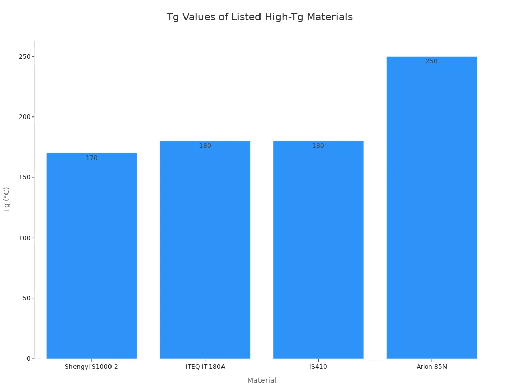
High Tg boards easily prevent layer delamination, material breakdown, and via barrel cracking from constant heat. Using these strong laminates protects the long-term reliability of all your important electronics.
Key Takeaways
High Tg circuit boards resist strong heat and prevent physical material damage.
Engineers keep top working temperatures 20 to 30 degrees below the material Tg rating.
High Tg materials prevent the copper layer from cracking and help keep the entire board from bending.
Certified manufacturing rules like IPC standards make sure circuits stay safe for a long time.
Understanding High Tg PCB Thermal Metrics
Glass Transition Temperature vs Decomposition Temperature
You must check regular parameters when picking pcb materials for tough electronics projects. Glass transition temperature shows the exact point where a hard base laminate becomes soft and flexible. Official IPC-4101 slash sheets group base laminate choices simply for engineers. Basic FR-4 has a glass transition range from 130°C to 140°C. Better high tg fr4 options like IPC-4101/26 and IPC-4101/126 increase this level to 170–180°C+. The key characteristics of high tg pcbs make sure your high temperature pcb keeps strong physical strength through heavy heat cycles.
Decomposition temperature measures chemical damage during long heat exposure. Standard FR4 shows a normal decomposition level from 300°C to 350°C. Meanwhile, high tg fr4 keeps a higher decomposition mark of ≥320°C. Getting close to these hot limits creates real burning, layer separation, and gas leaks. The high tg materials inside essential boards stop structural harm while building them. You can check high tg heat stability by using IPC-TM-650 2.6.7 thermal cycling test setups from −55°C to +125°C for 28 cycles. Strong high tg performance supplies necessary heat protection.
Material Standard | Glass Transition Temperature (Tg) | Decomposition Temperature (Td) |
|---|---|---|
Standard FR-4 | 130–140°C | ≥300°C |
High Tg FR-4 (/26, /126) | 170–180°C+ | ≥320°C |
Z-Axis CTE and Thermal Stress Performance
Unchecked heat effects alter base board sizes anytime working heat goes above Tg limits. Resin grows fast along the Z-axis in high heat. Too much heat growth tears copper plated through-holes apart, making inside cracks. Choosing high tg options stops Z-axis growth forces under heavy heat pressure. Picking a high tg substrate keeps complete signal quality clear throughout inner trace layers.
High tg options guard copper vias against bad physical cracking. A lower heat growth rate reduces physical strain on insulating materials through many layers. Your high tg pcb fights barrel cracking during hot lead-free soldering cycles. Steady high tg options hold heavy copper layers on power distribution boards. Using good substrate parts guarantees dependable long-term work for high-density hardware.
Long-Term Reliability Benefits of High Tg Substrates
Preventing Barrel Cracking and Layer Delamination
Turning power on and off repeatedly builds up intense heat changes inside your electronic equipment. Different expansion speeds between copper lines and resin create strong pulling forces along inside layers. Normal base materials break down fast under constant temperature changes. Picking a high tg resin system raises heat stability across every board layer. This high tg performance cuts down inner strain, stops small resin cracks, and prevents layer splitting during long use.
A high tg multilayer pcb protects delicate via holes during hot working conditions. High tg options give you a steady base board that manages heat growth in every direction. Lower Z-axis growth limits physical stress on copper plated hole walls. This solid protection prevents via barrel cracking under ongoing high heat. Using high tg materials keeps physical strength steady and ensures high-temperature endurance for your key equipment.
Mitigating Board Warpage and CAF Formation
Complex HDI layer stacks face heavy bending stress during hot building and assembly steps. Unequal heat growth across packed layer designs leads to bad board twisting and bent spots. Using high tg fr4 keeps size control across thin inner cores. High tg core stiffness gives helpful warpage control during repeated lead-free soldering runs. Strong material strength keeps your pcb flat and protects tiny surface-mount part solder connections.
Continuous electric voltage differences running across closely spaced circuit paths
Higher room moisture levels soaking into the nearby epoxy resin material
Constant working heat weakening the inside glass fiber layer connections
High working temperatures speed up Conductive Anodic Filament growth inside tight board patterns. Copper particles travel along inside glass fibers, causing sudden electrical shorts. Using high tg boards reduces small resin cracks under strong electric loads. Setting up high tg fr4 laminates keeps best electrical performance under tough working environments. Smart high tg substrate choice protects total signal quality, keeps board strength safe, ensures working reliability, and offers long-term reliability for your high tg pcb equipment.
Selecting High Tg Boards for Extreme Environments
Demands in Automotive Aerospace and Industrial Applications
You need strong materials when building electronics for tough jobs. Car engines, airplanes, and factory tools put heavy heat strain on circuit boards. Car engine parts deal with steady heat up to 120°C and quick jumps to 150°C. Regular FR4 breaks down fast in these hot spots. Using high tg boards lowers product failures from 2.5% to 0.3% in car battery systems running at 140°C.
Application | Operating Environment | Qualification Standard |
|---|---|---|
Automotive under-hood | Thermal cycling (-40°C to 125°C+), vibration | AEC-Q100/Q200, IPC-6012DA |
Aerospace avionics | Rapid thermal shock, mechanical shock | IPC-6012 Class 3 / IPC-6012FS |
Aerospace avionics need polyimide materials when working heat goes over 200°C. Flight tools face fast temperature changes and strong shaking. A high temperature pcb made with tough high tg resin holds its exact size and shape. This build protects inner copper lines from shaking damage. Industrial controls also need steady work up to 150°C for long periods. Using reliable pcb base materials keeps all parts strong in every use.
Applying the Thermal Safety Margin Rule
You must use a strict heat safety rule when choosing board materials. Circuit designers pick a target glass transition temperature 20–30°C higher than the highest working heat limit. If your board works continuously at 150°C, you should pick high tg laminates rated at 180°C or more.
Maintaining a 20–30°C thermal margin prevents the substrate from entering its glass transition phase during prolonged heat exposure.
Working near this temperature limit softens the base resin and puts heavy stress on copper plated through-holes. Selecting high tg options gives great heat safety over long working lifetimes. This extra temperature gap protects electric insulation and stops dangerous copper trace breaks. Choosing high tg boards keeps your high temperature pcb layout safe from unexpected shutoffs under heavy heat. Using a solid high tg pcb guarantees complete circuit safety and long-term project success.
Manufacturing Controls for High Tg FR4 Laminates
Lamination and Drilling Process Adjustments
You must adjust board factory settings when making a high tg multilayer pcb to fully harden the resin. Standard heat steps do not work well because high tg fr4 needs exact temperature controls. Factory workers dry the raw material sheets at 120°C for two hours before bonding to remove trapped water. Next, you apply heavy pressure while steadily raising heat up to 200°C. Holding this top heat level for up to two hours creates great strength across every board layer. You then cool the stack down slowly under pressure to stop bad board bending.
Drilling holes through tough high tg fr4 requires different tool settings. Strong glass fiber materials wear down normal drill bits, which creates extra friction heat and sticky resin smear. You must slow down drilling speeds and use sharp carbide tools to keep hole walls smooth. Proper chemical cleaning strips away leftover resin before adding copper. These building adjustments protect the physical board structure and keep electrical connections safe across inner circuit paths.
Compliance with IPC-4101 and IPC-6012 Standards
Official industry rules guide rigid base materials. Guidelines like IPC-4101E/98, IPC-4101E/99, IPC-4101E/126, and IPC-4101E/129 define these strong material types. Choosing approved pcb materials guarantees steady performance during lead-free soldering steps.
Specification Standard | Requirement Parameter | High Tg Target |
|---|---|---|
IPC-4101E | Glass Transition (Tg) | 170–180°C |
IPC-6012 Class 3 | Minimum Average PTH Copper | 25 μm |
IPC-6012 Class 3 | Solder Float Stress | 288°C for 10s |
IPC-6012 Class 3 | T288 Time to Delamination | ≥15 minutes |
Your high tg pcb maker uses these rules during careful quality checks. Strict testing proves that board heat growth stays very low below the Tg limit. Plated holes must fill up mostly with metal and survive hot solder tests at 288°C for ten seconds. Choosing certified high tg fr4 boards protects circuit lines and long-term board safety through years of tough daily use.
Picking high tg materials shields your electronic gear from failing out in the field. You get long-term reliability by keeping peak heat limits 20–30°C below the base material rating. This key heat buffer prevents layer splitting and protects clear signal quality across your whole board layout. Strong substrate choices also reduce mechanical z-axis stress on inner copper vias during severe heat swings. Following IPC standards strictly ensures complete physical strength in harsh working environments. Your design team avoids sudden product breakdowns by checking these factory production controls.
You must check project heat levels early when planning board layers and work with a certified high tg pcb maker to build durable pcb products.
FAQ
What Defines High Tg Substrate Materials?
A high tg fr4 laminate has a glass transition point of 170°C or higher. You pick these tough high tg materials to keep circuit boards strong during hot daily use. Basic pcb resins soften much earlier at 130°C to 140°C.
When Should You Specify a High Temperature PCB?
You need a high temperature pcb whenever steady working heat rises past 110°C. Keeping a 20°C to 30°C safety margin above peak heat stops material damage. You choose high tg options to shield pcb copper traces from strong physical stress.
How Do IPC Standards Ensure Circuit Reliability?
IPC-4101E rules set firm material strength targets for all base laminates. Circuit board makers meet IPC-6012 Class 3 goals to ensure total system quality. Approved boards must pass hot solder testing at 288°C for ten seconds without pcb layer separation.
How Do You Select a High Tg PCB Supplier?
You should review factory rules for resin bonding and hole drilling steps. A certified high tg pcb supplier runs board presses up to 200°C and uses sharp carbide drill bits. Checking IPC standards ensures great overall pcb build quality.
See Also
Why High TG FR4 PCBs Excel In Extreme Thermal Environments
Everything You Need To Know About Modern High Speed Circuit Boards
Essential Guidelines For Designing Reliable High Density Interconnect Circuit Boards
How To Build Durable Industrial PCBs For Today's Harsh Operating Conditions
A Complete Manufacturing Guide To Heavy Copper Multilayer Circuit Boards
