How Are PCB Stators Manufactured?

You may wonder how a motor stator comes from a circuit board. Manufacturers make PCB stators using the same multilayer processes as any circuit board. Instead of wound copper wire, flat spiral traces etched into the board layers carry the current. This design swaps bulky windings for precise copper patterns.
This new way changes the design and production sequence. The round board shape and the flat spiral design need tight control over trace width and layer alignment. Each layer must line up exactly so the spiral windings connect right. A small misalignment can break the circuit or cause a short between phases.
Key Takeaways
PCB stators use flat copper traces on circuit boards instead of coiled wire.
Design rules control trace width and layer alignment to stop short circuits.
Standard PCB making steps, like etching and lamination, form the stator windings.
Automated optical and electrical tests find problems early, so stators work reliably.
Encapsulation protects the traces and lowers motor noise, so the motor lasts longer.
Design Requirements for PCB Stators
Electrical and Thermal Constraints
You begin the design by thinking of the stator as a round board with flat spiral traces. Each phase has its own spiral path. Many designs put multiple phases on the same layer. This setup creates a special risk. A tiny gap error can connect two phases and cause a short circuit. You must set design rules that keep every phase separate.
During DFM review, you check trace spacing, layer count, copper weight, and other mechanical tolerances. This step makes sure your design fits manufacturing limits. The table below shows key rules that guide your layout.
Rule | Description |
|---|---|
Per-layer self-bucking | Cancel errors within each etched layer to improve stack tolerance. |
Fixed grid spacing | Use a uniform grid for trace placement to reduce rounding errors and shifts. |
Trace width ~70% of probe diameter | Typical optimal sensitivity; example uses 78% of probe diameter. |
Interleaved compact DQBuck layout | Best sensitivity for limited radial space. |
These limits directly shape your smallest trace and space, your copper thickness, and your layer count. Tighter spacing calls for thinner copper. More layers help you route phases without crossing.
Material and Stackup Selection
Your material choice must deal with heat from resistive losses. The copper traces carry current and make heat. A stackup with thicker copper lowers resistance and cuts that heat. But thicker copper limits your smallest trace width. You must balance these two needs.
The number of layers depends on your phase count and spiral shape. A single-phase design may need only two layers. A three-phase design often needs more. Each added layer gives you more routing space. It also raises cost and makes alignment harder. You pick a stackup that meets your electrical needs without wasting material.
Core Fabrication Steps
Fabricators make PCB stators on the same machines that build normal circuit boards. The steps are familiar: imaging, etching, lamination, drilling, and electroless copper plating. The difference is precision. Flat spiral windings need tighter limits on trace width and layer alignment. A tiny drift in either one can ruin the coil pattern.
Imaging and Etching of Traces
You begin with a DFM review. This step checks layer count, finished copper, trace spacing, via structure, outline tolerance, slots, and mechanical datums. After the review passes, imaging puts the spiral coil pattern onto the copper-clad laminate. A photoresist layer hardens where copper must stay. Etching then removes the exposed copper and leaves the flat windings behind.
High-precision etching matters most here. The copper traces carry the motor current, so their cross-section sets resistance and current capacity. Undercut traces raise resistance and heat. Over-etched gaps can short two phases together. You control both by matching copper weight to your smallest feature size. The table below shows the general guide.
Copper Weight | Minimum Recommended Trace Width and Spacing |
|---|---|
1 oz | 3.5 mil (0.089 mm) |
2 oz | 8 mil (0.203 mm) |
3 oz | 10 mil (0.254 mm) |
4 oz | 14 mil (0.355 mm) |
These values are a general guide for setting design rules. Different fabrication facilities may hold slightly different abilities. Printing narrow traces is easier than etching narrow gaps between them. For consistency, you should use the same size for both spacing and trace width.
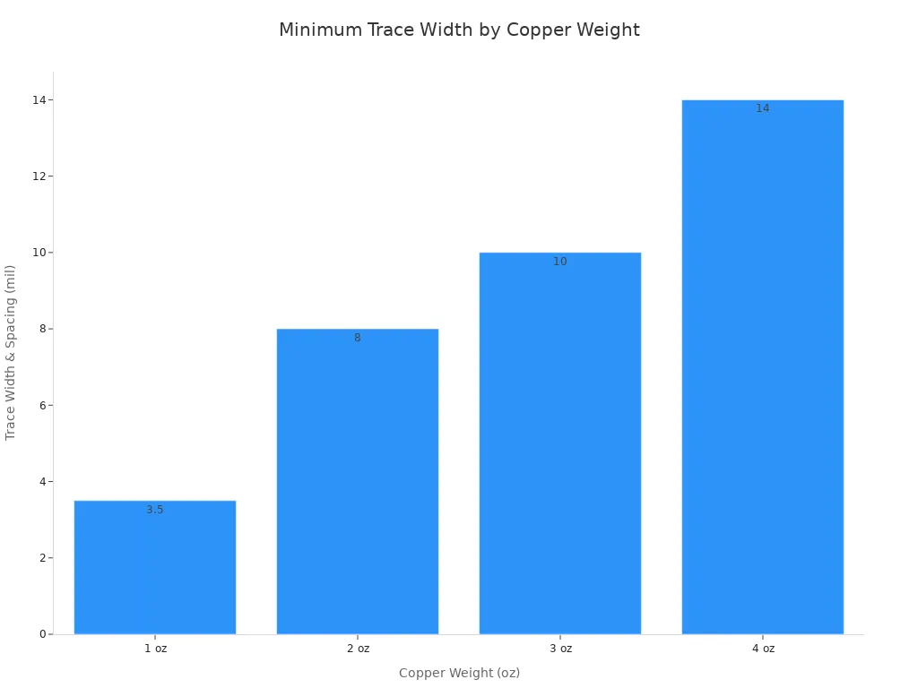
Copper weight and layer count control resistance, fill factor, and conductor distribution, while finished copper, etching capability, spacing, and registration are key manufacturing factors for PCB stators.
Lamination, Drilling, and Plating
After etching, you stack the inner layers and laminate them under heat and pressure. The resin bonds the layers into one solid board. Registration matters most at this stage. Each layer must line up with the others so the spiral windings connect through vias. A shift of even a few mils can break the phase circuit.
Drilling comes next. The drill makes holes for vias and mechanical mounting. You then plate the holes with electroless copper. This thin copper layer makes the walls conductive and links the layers together. Plating also thickens the traces on the outer layers.
The full sequence follows a clear order:
Do a DFM review to confirm layer count, finished copper, trace spacing, via structure, outline tolerance, slots, and mechanical datums.
Carry out imaging and etching to form repeatable coil patterns while controlling conductor width, spacing, and copper balance.
Every step runs on automated equipment. That automation keeps unit cost low and output high. You get motor-grade windings without a single turn of wire.
Inspection and Testing for PCB Stators
Solder Mask and Surface Finish
After etching and plating, you add a solder mask to the board. This layer protects the copper traces from damage and rust. For PCB stators, it also stops solder bridges between the tight spiral coils. You leave openings only where electrical connections are needed.
Next, you pick a surface finish for the exposed copper pads. Two common types are ENIG and OSP. ENIG gives a flat, strong surface that resists rust. OSP costs less and works well for short storage. Your choice depends on how you will assemble the stator and how long you need to store it.
Automated Optical and Electrical Test
Once the finish is done, every panel gets an automated optical inspection (AOI). This machine uses cameras to check each board against the design. AOI finds three main defect types in mass-made stators:
Shorts — unwanted connections between traces
Opens — breaks or gaps in the path for current
Insufficient spacing — not enough room between parts, which can cause shorts or sparks
After AOI, you run electrical testing. A probe tester checks if each spiral coil connects correctly and that phases do not touch. This step finds hidden errors that the camera might miss.
Standard circuit board test gear lets you make PCB stators fast and cheaply.
The same automated lines that build and test normal boards handle your stator panels. You get fast output and steady quality without building a custom line.
Panelization and Final Assembly
Panel Layout and Depaneling
Round boards waste more material than square ones when cut from a standard panel. You must plan the layout carefully to use as much of the panel as possible. Your design team puts many stator circuits on one large panel. The goal is to fit as many circles as possible into the space. A good layout puts six to eight stators on a single panel. This lowers the cost for each unit. It spreads fixed costs across more parts. Every extra stator per panel cuts down on waste.
After making and testing, you separate each stator from the panel. Routing and scoring are the two common ways to do this. Routing uses a small cutting bit. The bit moves around each stator outline. Scoring cuts a V-shaped groove along the lines where you will break the boards apart. You then snap them apart by hand or with a machine. Both ways work well with standard PCB tools in your factory. The depaneling process leaves clean edges. You do not need any extra finishing.
Core Bonding and Encapsulation
The etched PCB layers have the copper windings. They do not yet make a full motor stator. You need to join the PCB stack to a magnetic core. This core gives the iron path for magnetic flux. You put an adhesive between each layer. You press the stack together with heat. The bond makes a rigid part. It keeps all layers perfectly lined up. This alignment matters for motor efficiency.
Encapsulation is the last step in the assembly process. You cover the copper traces with a composite material. This material fills all gaps between the spirals. It seals the traces from moisture and dust. The encapsulation also stops the copper from shaking when current flows through it. Vibration creates noise in old-style stators. The solid composite absorbs that energy. The motor runs quieter because of this. The encapsulation helps the stator handle heat changes. It locks the traces in place. It stops movement as the board heats and cools.
This final assembly process gives PCB stators a clear edge over wound stators. You get a quiet, long-lasting motor part. It works well in standard high-volume production lines.
You now know the full process for making PCB stators. It starts with design rules based on the round shape and flat spiral traces. Standard multilayer fabrication comes next, with tighter control on trace width and layer alignment. Automated optical and electrical tests find mistakes before panelization. The final steps join the stack to a magnetic core and encase the copper.
This method uses proven PCB making. You get cheap, dependable, and quiet stator parts. Encapsulated PCB stators also last much longer under voltage stress. BWP tests showed their insulation survives 80 to 100 times longer than mica tape systems.
Get in touch with the engineering team for help with prototypes or design for manufacturing.
FAQ
How does a PCB stator differ from a traditional wound stator?
A traditional stator has copper wire rolled into coils. A PCB stator uses flat spiral traces etched into board layers instead of coils. This design gets rid of bulky windings and uses normal circuit board methods. The final part is thinner, quieter, and works in automated assembly lines.
Why does trace width matter so much in PCB stator fabrication?
The copper traces carry the motor's current. Their cross-section decides resistance and how much current they can handle. Traces that are too thin increase resistance and heat. Gaps that are too wide can connect two phases and cause a short. You need to match copper weight to your smallest trace size to keep the motor working properly.
What defects does automated optical inspection catch?
AOI cameras check each board to see if it matches the design. They spot three main kinds of defects: shorts between traces, opens or breaks in the current path, and not enough space between parts. Finding these mistakes early stops bad stators from getting to final assembly.
How many stators fit on one panel?
A well-planned panel can hold six to eight stators. Round boards waste more material than square ones. Putting more circles in the space reduces the cost per unit. Each extra stator on a panel shares the fixed costs across more parts.
Why do manufacturers encapsulate PCB stators?
Encapsulation coats the copper traces with a composite material. This protects the traces from moisture and dust. It also stops the copper from vibrating when current flows. The solid composite absorbs vibration energy, so the motor is quieter. Encapsulated stators also last much longer when exposed to voltage stress.
See Also
A Complete Guide To The Printed Circuit Board Manufacturing Process
Discover How Printed Circuit Boards Are Made In Detailed Fabrication
An In-Depth Look At How Multilayer PCBs Are Manufactured
Rigid PCB Production: Materials, Methods, And Quality Standards For Industry
The Manufacturing Process For Aluminum PCBs With Insulation Holes
