Multilayer PCB Manufacturing for PCB Stators
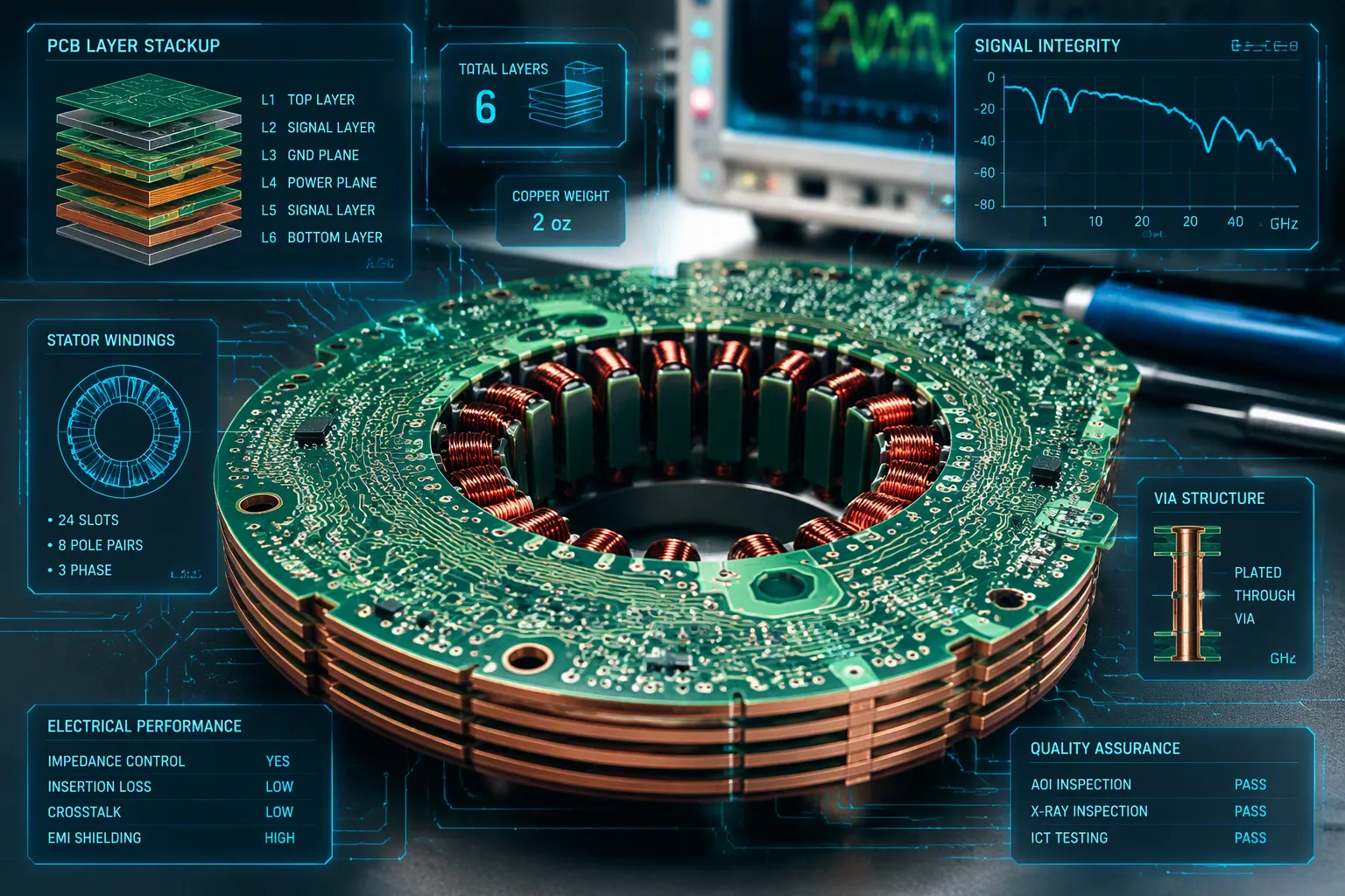
Multilayer pcb manufacturing turns a stack of copper-clad laminates into a finished board. You begin with coil design and material selection. Then you go through lamination, drilling, plating, etching, and testing. Pcb stators take the place of traditional copper windings in electric motor technology. This change makes axial flux motors much lighter.
The Infinitum Electric axial-flux motor with a PCB stator is said to have half the weight and size of a traditional induction motor. This means a 50% weight reduction compared with conventional wire-wound stator designs.
Each pcb stage needs tighter control than a standard board. A finished pcb must pass strict tests. Pcb stator technology rewards that care with better performance.
Key Takeaways
PCB stators take the place of heavy copper windings, lowering motor weight by as much as 80%.
Use high-temperature substrates like polyimide to handle heat above 200°C.
Keep the layers lined up within ±0.05 mm, and use plating that is at least 50 µm thick for steady current.
Automated PCB manufacturing makes sure stators for axial flux motors are always the same quality.
Designing the Multilayer PCB Stator
Coil Patterns and Layer Assignment
You begin the design by placing printed circuit coils on several layers. Each layer has a set of spiral or wave-shaped traces. These traces take the place of the copper wire windings in a regular motor. You link the layers with vias to make one continuous current path. This method is the core of pcb stator technology.
The number of layers you need depends on the torque you want. A high-performance axial flux motor might use 48 layers. Designers build this stack from four 12-layer HDI modules. Standard PCB motors often use just 6 layers. More layers give you more turns and higher torque density.
A coreless design takes away the iron teeth that hold wire coils. Without those teeth, the rotor never feels a magnetic pull toward a slot. This feature gets rid of cogging torque by nature. The motor runs smoother at low speed.
Modern multilayer circuit board production has made printed circuit coils cheaper and easier to build. You no longer need custom winding machines. You can panelize many stators on one board and put them together on an automated line.
Thermal and Current Design Rules
Copper thickness and trace geometry set your current capacity. A common high-current design uses 6 mm trace width, 6 mm trace spacing, and a 5 mm interlayer gap. That stack carries 1.0 A with 1 oz copper. The table below shows how dimensions change with the application.
Application | Trace Width | Trace-to-Trace Spacing | Other Dimensions |
|---|---|---|---|
Miniaturized multilayer PCB boards | ≈ 50 μm | ≈ 50 μm | Trace thickness < 10 μm; board length > 1 m |
High-current accelerator search-coil | 3.5 mm | 7.0 mm (center spacing) | 6 PCB segments, each 535 mm long; 15 windings per segment; sampled aperture 101.5 mm |
Heat is the other limit. Current through a printed circuit board stator trace makes the temperature rise. You must choose a substrate that can handle that heat without getting soft. You also need insulation that stands up under voltage stress and repeated thermal cycling. A printed circuit board technology review early in the design phase saves rework later.
PCB Stator Technology Materials
High-Temperature Substrates and Prepregs
Heat is the biggest problem for a stator. Current in copper traces creates heat. The base material must handle that heat without softening or breaking. Standard boards have a glass transition temperature between 130°C and 180°C. Better materials go above 200°C. The breakdown temperature must be higher than solder temps of 200–250°C. You also want low thermal expansion along the Z-axis, below 70 ppm/°C.
Several materials meet these demands. The table below compares common options.
Material | Type | Max Operating Temperature | Notes |
|---|---|---|---|
Kapton® | Polyimide film | up to 400°C | Used in aerospace, printed circuits, and traction motor applications |
Cirlex® | All-polyimide laminate | up to 400°C | Similar properties to Kapton® HN; used for slot insulation |
PEEK | Polyetherketone film | 260°C | Chemical, hydrolysis, and wear resistance; low outgassing |
PTFE | Fluoropolymer | N/A | Low-polarity, low-loss resin; combined with Kapton® FN for heat-sealable insulation |
PTFE works well for high-frequency and high-temperature uses. You can combine it with Kapton® FN to make heat-sealable insulation.
Copper Thickness and Insulation
Copper thickness decides how much current you can use. A thicker copper layer carries more current without getting too hot. You pick the thickness based on the steady current your motor needs. The trace width and spacing also matter. A high-current design might use 6 mm trace width and 6 mm spacing with 1 oz copper. That stack carries 1.0 A. Thicker copper handles higher currents.
Insulation must handle voltage stress and repeated heating and cooling. The dielectric layer between copper layers stops short circuits. It must stay strong as the board heats and cools during use. A weak insulation system breaks down over time. You need materials that keep their dielectric strength at high temperatures. This care helps your pcb stator technology work reliably in demanding motors.
Multilayer PCB Manufacturing Steps
The work process has three easy steps: structuring, lamination, and through-hole plating. Structuring makes coil patterns. Lamination joins the layers into one board. Through-hole plating links them electrically. This process is the basis of multilayer pcb manufacturing for a stator.
Structuring and Inner Layer Imaging
You start with copper-coated laminates. Each laminate becomes one layer of your pcb stator. You coat the copper with a light-sensitive resist. Then you shine UV light through a phototool to expose the resist. The phototool holds your coil pattern. After developing, the resist protects your traces. Etching later removes the rest. Your pcb needs this step.
Registration tolerance matters more than in a normal board. Your coil layers must line up perfectly. If they shift, vias cannot connect traces reliably. A layer-to-layer tolerance of ±0.05 mm keeps identical coil patterns aligned. Hold positional tolerance between layers to ≤0.1 mm. Automated optical inspection checks both. Parallel current distribution variance stays within ±8% after lamination.
Parameter | Requirement | Purpose / Verification |
|---|---|---|
Layer-to-layer registration tolerance | ±0.05 mm | Ensures identical coil patterns align across layers; verified by AOI before lamination |
Positional tolerance between layers | ≤0.1 mm | Maintains alignment of corresponding coil traces connected via through-hole vias |
Parallel current distribution variance | within ±8% | Confirms alignment quality across layers after lamination |
Lamination and Through-Hole Plating
Next you stack inner layers with prepreg sheets between them. Prepreg acts as glue and insulator. You align each layer with registration pins. Then heat and pressure melt the prepreg and bond the layers into one stiff board.
You drill via holes after lamination. A standard FR-4 board with 4–6 layers and 1.6 mm total thickness uses 0.3 mm vias. They go through all copper layers. You plate the hole walls with copper to make electrical connections.
Standard plated through-hole (PTH) plating is 20–30 µm (0.8–1.2 mils). High-current designs work better with 50 µm or more. Thicker plating lowers resistance and carries more current without too much heat. It also survives thermal cycling better.
IPC Class | Average Plating Thickness | Minimum at Any Point |
|---|---|---|
Class 1 | 20 µm (0.8 mil) | 18 µm (0.7 mil) |
Class 2 | 20 µm (0.8 mil) | 18 µm (0.7 mil) |
Class 3 | 25 µm (1.0 mil) | 20 µm (0.8 mil) |
For Class 3, specify 25 µm minimum average with an internal target of 30 µm. Ductility matters; elongation must be ≥18% per IPC-6012 Class 3. Low-ductility copper cracks under thermal stress.
Doubling plating from 1 mil to 2 mil roughly doubles the copper cross-section. Via resistance drops from 2–3 mΩ to 1–1.5 mΩ. Current capacity rises 35–40% before the same temperature rise. The tradeoff is cost; plating adds 15–25% to fabrication cost.
You can estimate PTH current with the simplified IPC-2152 relation: I = 0.048 * A^0.44 * ΔT^0.725. I is maximum current in amps, A is the cross-sectional area of the PTH copper plating in mils², and ΔT is the maximum temperature rise in °C above ambient.
High aspect ratios create another risk in multilayer pcb manufacturing. Deep, narrow holes plate unevenly. Weak spots can form inside the hole. These spots limit current capacity and reliability. Your electronic manufacturing partner should have extensive production abilities to control plating uniformity. Discuss hole size, board thickness, and target current for your motors early.
Etching, Finishing, and Testing the PCB
Etching Coil Traces and Surface Finish
After plating, you etch away the copper you don't need. A chemical bath dissolves exposed copper and leaves your coil traces behind. The resist you developed earlier protects the traces you want to keep. This step shapes every winding in your stator.
Etching needs tight control. Over-etching makes traces thinner and raises resistance. Under-etching leaves copper bridges that short nearby turns. You watch bath chemistry, temperature, and dwell time to keep trace width in range. For a high-current stator, even a small width loss matters because resistance rises and heat builds.
Solder mask and surface finish protect the finished board. Solder mask covers everything except the pads and connection points. It stops solder bridges and shields traces from moisture and contamination. Surface finish keeps exposed copper from oxidizing before assembly. Your choice of finish affects long-term reliability under motor operating conditions.
Surface Finish | Reliability | Corrosion Resistance | Typical Use / Notes |
|---|---|---|---|
OSP | Cost-effective and flat; suitable for fine-pitch and quick-turn builds | Not specifically noted as corrosion-resistant | Limited in multi-stage assembly due to handling sensitivity |
HASL | Economical and good for general-purpose and through-hole builds | Not specifically noted as corrosion-resistant | Not ideal for fine-pitch devices because of uneven surfaces |
Immersion silver | Low loss; excellent for RF and microwave applications | Some sensitivity to tarnishing | Good electrical performance, but tarnishing may affect long-term reliability |
Immersion tin | Flat and solderable; suited for fine-pitch assemblies | Not specifically noted as corrosion-resistant | Best for short-term use due to tin whisker risk |
ENIG | Reliable, planar, and widely used for high-density, high-performance designs | Good corrosion resistance implied by high-performance use | Used in aerospace, medical, and communication systems |
ENEPIG | Premium and highly reliable; suitable for wire bonding and mission-critical electronics | Improved corrosion resistance over ENIG | Best choice when superior corrosion resistance and reliability are required |
ENIG and ENEPIG work well for demanding stator builds. Both give you flat surfaces and strong corrosion resistance. ENEPIG adds extra reliability for mission-critical electronics. Pick the finish that fits your assembly process and operating environment.
Electrical and Reliability Testing
Testing confirms your board is ready for motor assembly. You start with electrical tests. Continuity checks verify that every coil trace connects through the vias. Isolation tests confirm that no short circuits exist between layers or nearby turns. You measure resistance across each phase to catch weak vias or thin traces.
Reliability tests push the board beyond normal use. Thermal cycling heats and cools the stator many times. This test shows whether plated holes crack or insulation breaks down. You also check dielectric strength to confirm the insulation holds under voltage stress. These tests matter because a stator inside a motor faces constant heat and vibration.
A finished pcb must pass every check before it leaves the line. Automated optical inspection catches surface defects. X-ray inspection looks inside plated holes for voids or weak plating. Any board that fails goes back for review or scrap. This discipline keeps defective units out of your motors.
Multilayer pcb manufacturing rewards careful process control at every stage. Etching shapes your windings. Surface finish protects them. Testing proves they will survive real operating conditions. When all three steps pass, your stator is ready to build into an axial flux motor.
Axial Flux PCB Stator Motor Technology Advantages
Lighter, Cooler, and More Efficient
Taking out the iron core and copper windings gives you big gains. An axial flux PCB stator motor can cut motor weight by up to 50% compared with older designs. The thin copper traces spread heat over a wide surface. This keeps the stator cooler when it is working hard. A cooler stator runs better and lasts longer.
The flat shape also allows an ultra-thin disc form. This shape fits into tight spaces where a bulky wire-wound motor cannot go. You can build combined assemblies that join the motor with other parts. These features make axial flux PCB stator motors great for next-generation motor solutions.
Compared with Wire-Wound Stators
PCB stator electric motors win when it comes to repeatability. The coil pattern comes from artwork and a standard PCB process. Every board matches the design file. Wire winding depends on human skill and machine setup. That process causes differences from unit to unit.
Decision Factor | PCB Stator Motor | Conventional Wound Motor |
|---|---|---|
Winding repeatability | Defined by artwork and PCB process | Depends on winding and assembly process |
Cogging torque tells a different story. Traditional brushless motors show a stop-and-go cogging zone when commutated by shaft position. PCB stator technology gets rid of cogging torque by design. You feel this difference as smoother torque at low speed.
Capability | Traditional Brushless Motor | PCB Stator |
|---|---|---|
Low cogging / smooth torque | No | Yes |
Automated assembly changes the economics of motor production. You remove copper wire winding entirely. This removes human error and supports consistent dimensions. Design files are generated automatically for PCB manufacturers worldwide. You use global PCB industry capacity for fast prototyping and full-scale production. The result is unmatched flexibility, faster time-to-market, and lower cost.
These benefits serve high-performance electric motors, specialized electric motors, and sustainable, high-performance electric motors alike. Whether you build electric machines for pumps or fans, PCB stator electric motor technology offers a clear path forward. The same advantages apply across electric motor solutions and electric motor technology. For stators in traditional motors, the printed circuit board stator machines approach delivers repeatable quality at scale.
You now understand the whole process of making a multilayer PCB stator. You design coil patterns and choose high-temperature materials. You laminate layers, drill vias, plate copper, and etch traces. You also apply finish and run tests. Each step helps the next one.
PCB stator technology gives you more power in a smaller space. It also makes motors lighter and spreads heat better. Automated assembly makes motor production repeatable. Use these process tips for your next design or supplier check. Talk to your manufacturing partner early. This one habit cuts risk, shortens lead time, and keeps your PCB ready for tough motors.
FAQ
How many layers does a stator pcb need?
The number of layers you need depends on the torque you want. A high-performance axial flux motor might use 48 layers. Designers build this stack from four 12-layer HDI modules. Standard PCB motors often use just 6 layers. More layers give you more turns and higher torque density.
Why does via plating thickness matter so much?
Thicker plating lowers resistance and carries more current. Standard plated through-holes run 20–30 µm. High-current designs work better at 50 µm or more. For Class 3, specify 25 µm minimum average with an internal target of 30 µm.
How tight must layer registration be?
Your coil layers must line up perfectly. A layer-to-layer tolerance of ±0.05 mm keeps identical coil patterns aligned. Hold positional tolerance between layers to ≤0.1 mm. Automated optical inspection checks both before lamination.
Which surface finish suits a stator?
ENIG and ENEPIG work well for demanding stator builds. Both give you flat surfaces and strong corrosion resistance. ENEPIG adds extra reliability for mission-critical electronics. Pick the finish that fits your assembly process and operating environment.
What weight savings can you expect?
An axial flux PCB stator motor can cut motor weight by up to 50% compared with older designs. The thin copper traces spread heat over a wide surface. This keeps the stator cooler when it works hard.
See Also
Challenges In Prototyping And Fabricating Multilayer Circuit Boards
Step By Step Guide To Manufacturing Multilayer Printed Circuit Boards
Fabrication Steps For Multilayer Rigid Flex PCB Assemblies
Industrial Uses And Applications Of Multilayer Printed Circuit Boards
Complete Overview Of The Printed Circuit Board Fabrication Process
