PCB Stator Current Capacity and Copper Loss
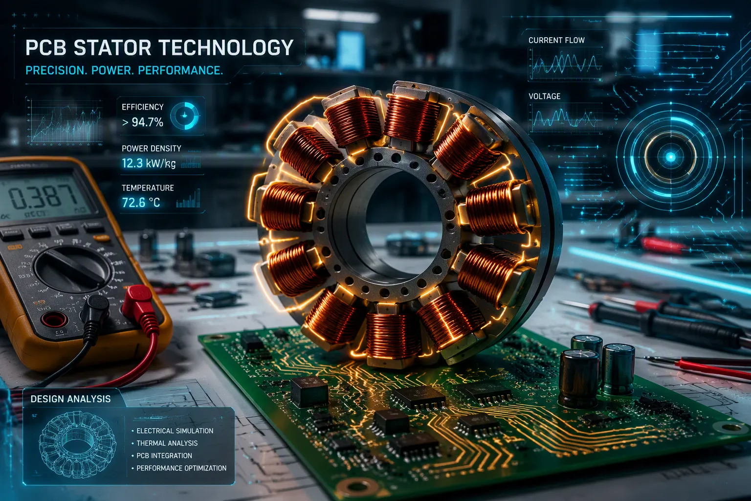
A PCB stator current capacity is not a set number. The allowed temperature rise decides it, and copper loss (I²R) causes that rise. Current capacity is the most current a trace can carry while staying under a safe temperature limit. Copper loss is the heat made when current flows through the resistance of the trace.
How do engineers figure out the most current for a given trace? How do they design for it? This article explains the basics of loss and heat, the design parameters that matter, calculation methods, ways to lower loss, and thermal management for an axial flux PCB stator.
Key Takeaways
The current a PCB stator can handle depends on how much its temperature is allowed to rise. Copper loss is what causes that rise.
The width, thickness, and length of the trace decide its resistance. Lower resistance means less heat when the current stays the same.
Use wider traces, thicker copper, and parallel layers to lower copper loss. Thermal vias help move heat away.
Active cooling methods, such as heat sinks, airflow, and potting, keep the stator cool. They let it handle higher current without getting too hot.
Copper Loss and Heat in a PCB Stator
A PCB stator uses traces printed on the board instead of wound coils. This design changes where the loss happens. The heat is made right in the board copper, not in wire windings. This fact shapes every thermal decision.
I²R Loss and Temperature Rise
The copper loss follows the basic I²R formula. The trace resistance sets the heat for a given coil current. The stator usually has higher resistance than wound designs. The main reason has to do with density. Wound designs pack material tightly. Flat copper traces sit between fiberglass layers. This construction limits the material available in each layer. Higher resistance makes more heat at the same amperage.
Copper losses will be high because you typically cannot get as good of a fill factor with PCB traces as with wound copper, so the phase resistance will be high, which impacts the efficiency.
The design carries two loss types. DC loss comes from the steady trace resistance. AC copper loss comes from eddy currents. The frequency-dependent copper loss grows as motor speed goes up. DC loss usually dominates at low speeds. AC loss becomes significant at high speeds. These two parts together set the total heat in the board.
A representative example shows typical magnitudes. One design makes 48.52 W of DC loss. The same design makes only 5.2 W of AC copper loss. The DC part is about nine times larger than the AC part. This ratio changes with motor speed and trace geometry. Designers must think about both types when finding the safe operating point.
The main issue here is copper density and mechanical support. The former is simply due to fiberglass construction of PCBs.
The IPC-2221 standard gives a method for estimating temperature rise. Section 6.2 relates trace cross-sectional area to the allowable rise. The formula takes the area in square mils, the amperage, and the temperature rise in degrees Celsius. The following table shows example values from this standard.
Current | Trace specification | Temperature rise |
|---|---|---|
1 A | 1 oz copper, 0.3 mm trace | 10 °C |
1.2 A | 1 oz copper, 0.3 mm trace | 15 °C |
Many PCB design tools use a default limit of ∆T = 20 °C for safe continuous operation. This limit gives a reasonable safety margin for most applications.
Thermal Resistance and Heat Paths
Thermal resistance describes how easily heat flows from a trace to the air. Low resistance keeps the board cool. High resistance traps heat inside the layers.
The heat dissipation path starts at the trace. Heat moves into the PCB material. The thermal conductivity of FR-4 fiberglass is low. This property makes it a poor conductor of heat. Heat then travels through vias to other layers. These vias connect inner traces to outer surfaces. From the outer surfaces, heat moves into the surrounding air through convection and radiation. The complete path sets the final trace temperature.
The flat pcb windings in an axial flux motor create a unique thermal challenge. The traces sit very close to the air gap. This position limits the space available for heat dissipation. The motor windings make heat in a thin layer. The stator windings must move that heat through the entire board stackup. Effective thermal management demands careful via placement and layer selection.
Copper foil coils have shorter thermal paths than wound coils. The foil lies flat against the board, creating more surface area for heat transfer. The printed circuit board coils spread heat evenly across the board surface. This even spread stops hot spots that could damage the board.
Designers must balance the copper loss budget with the available cooling capacity. Each motor has a maximum allowable temperature. Going over this temperature damages the PCB or shortens motor life. The combination of trace geometry, board materials, and cooling method sets the practical limit.
Design Parameters for PCB Stator Current Capacity
Trace Width, Thickness, and Length
Trace shape sets resistance. Width, foil thickness, and length work together to set loss in the winding. Cross-sectional area drives ampacity. Narrow traces with thin metal make high resistance. High resistance makes more heat under electrical load.
The foil follows standard weight ratings. One ounce per square foot gives a thickness of 0.0014 inches. IPC-2221 gives a formula for these values. The carry capacity equals K times ΔT^0.44 times A^0.75. K is 0.024 for internal layers. K is 0.048 for external layers. ΔT is the temperature rise. A is the cross-sectional area in square mils.
IPC-2152 includes a reference table for 1 oz foil at a 10°C temperature rise.
Amperage (A) | Required Trace Width (mil) |
|---|---|
1 | 10 |
2 | 30 |
3 | 50 |
4 | 80 |
5 | 110 |
6 | 150 |
7 | 180 |
8 | 220 |
9 | 260 |
10 | 300 |
The pattern between metal thickness and conductor width is clear. For 17 A at 5°C rise, a 1 oz trace needs 60 mm. A 2 oz trace needs 30 mm. A 3 oz trace needs 20 mm. Thicker foil does not double ampacity directly. At 0.05 inch width and 10°C rise, 0.5 oz foil carries 1.5 A. One ounce carries 2.6 A. Two ounces carries 4.0 A. Trace length also matters. Longer traces make more heat.
The pcb stator current capacity depends on all three parameters.
Layers, Ambient, and Current Density
Layer count gives designers options. For this board type, multiple layers make parallel paths. Each layer carries part of the load. This lowers overall resistance. It cuts heat per layer. Ambient temperature sets the starting point. A board in a 25°C room allows more rise than a board in an 85°C enclosure. The allowable rise sets the limit.
Practical designs for a pcb stator motor run between 5 and 15 A per square millimeter. Higher density makes more heat. Lower density uses more board space.
Analysis tools for an axial flux pcb motor offer two loss models. The first estimates DC loss only. The second adds AC loss from eddy effects. Many first tries use the DC only model. It gives a fast estimate of minimum heat dissipation.
Copper foil in this winding structure makes flat conductors. This shape helps heat transfer. The flat surface touches more board material. Each trace acts as a heat spreader. For pcb stator motors, heat moves from the trace through the laminate. It leaves through vias or the board surface. Thicker foil cuts resistance. It helps thermal connection across layers.
The chart below shows ampacity for different metal thicknesses at three temperature rises.
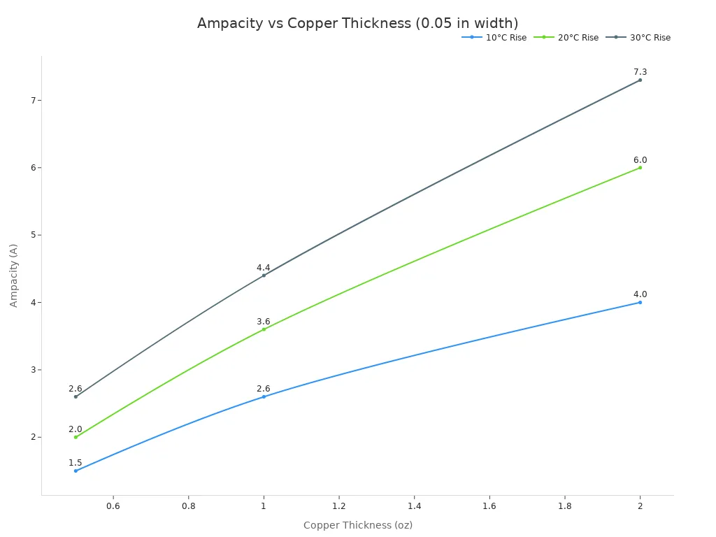
Designers must match conductor width to the target amperage. For an axial-flux pcb motor, this choice sets the winding capacity directly. Wider traces and thicker foil raise the limit. Board costs go up with heavier foil and more layers. The design must balance performance with manufacturing cost.
Calculating Maximum Current
There is no single amp rating for a PCB trace. The allowed temperature rise sets the limit. A designer picks a rise target, then finds the trace shape that stays under it. This method works for any pcb stator current capacity calculation.
IPC Standards and Charts
Two standards guide this work. IPC-2221 uses legacy empirical data and a simple formula. IPC-2152 uses modern test and simulation data and adds correction factors.
Aspect | IPC-2221 | IPC-2152 |
|---|---|---|
Data basis | Legacy empirical data | Modern test and simulation data |
Copper plane effect | Not modeled directly | Modeled explicitly |
Board thickness effect | Not modeled directly | Included |
Typical result | More conservative | Closer to real board behavior |
The newer standard gives much more detail:
The new standard IPC-2152 provides more than 100 different figures and lets you take into account many additional factors, such as thickness of PCB and conductors, distance to a copper plane, etc.
Several inputs go into any chart.
Parameter | Description |
|---|---|
Layer Type | Internal or external conductor layer |
Ambient Temperature (°C) | Surrounding temperature of the operating environment |
Conductor Thickness (oz) | Conductor weight of the trace |
Temperature Rise above Ambient (°C) | Acceptable increase |
Conductor Width (mils) | Trace width |
Maximum Current Capacity (A) | Target amperage |
Copper Plane Influence | Presence of a plane affects heat sinking |
Temperature rise drives the result. A 10°C rise works for heat-sensitive parts. A 20°C rise is a common middle choice. A 30°C rise is more aggressive and needs careful thermal management. Raising the allowed rise to 20°C cuts the required trace width by about 25–30%. External layers get rid of heat better than internal ones, so internal traces need more width for the same amperage.
The IPC-2152 workflow follows a clear order. Start with a baseline cross-sectional area from the charts for the target amperage and allowed rise. Apply a correction for conductor thickness. Apply a correction for board thickness and nearby metal. Apply a correction for plane proximity and thermal spreading. Turn the corrected area into a usable trace width.
Simulation and Measurement
Chart methods have limits. IPC-2152 nomographs tend to overestimate the trace width needed to hold a given rise. The calculators only work when traces sit more than 1 inch apart, which real boards rarely allow. Closely spaced parallel traces at the same amperage can run hotter than a single trace, and the calculator misses that case. It also ignores heat sinks, convection cooling, and conduction into the enclosure.
Factor | IPC Chart Method | Thermal Simulation |
|---|---|---|
Copper weight effects | Not accounted for | Heavier copper spreads heat |
Dielectric thickness | Not considered | Thinner dielectric pulls heat away |
DC power losses | Not modeled | Thinner conductors lose more DC power |
Overall accuracy | Overly conservative | Realistic for actual stackups |
Thermal simulation fills these gaps. It models the real spacing, stackup, and heat dissipation path. Bench measurement then confirms the result. A designer runs the axial flux pcb motor at load and records the winding temperature under the intended load profile. This step gives motor-specific thermal validation that no chart can provide. The axial-flux pcb motor benefits most from this loop, because its traces sit close to the air gap where heat dissipation is hardest.
The allowed current is not a fixed number. It is whatever amperage keeps the trace below the chosen rise. Change the cooling, the conductor weight, or the ambient, and the limit moves.
Reducing Copper Loss in the Stator
Cutting copper loss in a PCB stator begins with lowering resistance. Less resistance means less heat at the same current. Designers have a few ways to reach this goal.
Wider Traces and Thicker Copper
Trace width changes resistance directly. A wider trace has less resistance. It also spreads heat over more of the board. The manufacturing process limits how far this can go.
Minimum trace widths and spacing may need to be bigger for 6 oz/ft² metal than for 1 oz/ft² metal. This limit matters a lot for motor drive PCBs, which often need heavy copper to handle high currents.
A few things push up fabrication costs for copper pours:
Trace widths under 5 mils and thickness other than 1 oz (1.4 mils) raise costs.
High-power motor designs need very wide traces or thicker pours.
Special etching steps are needed for heavy copper (3-10 oz/ft²).
Lamination cycles must be changed.
Design rules for spacing and via size must be adjusted.
Internal traces need 2-3 times the width of external traces to carry the same current, because heat leaves them more slowly.
Thicker copper foil cuts resistance by a lot. A 2 oz foil carries more current than a 1 oz foil at the same width. Each step up in weight makes manufacturing harder. The designer must weigh better performance against board cost.
Parallel Paths and Thermal Vias
Parallel paths give another way to lower resistance. Several layers share the load together. Each layer carries part of it. This cuts overall resistance without making single traces wider.
Multi-via structures make a big difference. They join layers together. This link cuts phase resistance at cold and operating temperature. The gain is large. Multi-via structures can cut phase resistance by about 11.82%. They lower DC winding loss by about 12.1%. Total winding losses fall by roughly 15.09%. These numbers come from real design comparisons.
Layout choices also matter. Shorter paths mean less resistance. Designers route traces to keep them short. They put vias near the points of connection. This keeps paths as short as they can be.
Thermal vias help move heat away. They carry heat from inner layers to the board surface. More vias make the heat path better. The stator windings stay cooler. The axial flux pcb motor gains from this approach. The axial-flux pcb motor has traces close to the air gap. Good thermal management matters most in this design.
Copper traces in parallel share the load better. The design balances load across layers. No single layer carries the whole load. This balance cuts hot spots and makes motor life longer.
Thicker copper foil also moves heat better through the board stackup.
Thermal Management for an Axial Flux PCB Motor
Heat Sinking, Airflow, and Potting
The axial flux pcb motor needs active cooling systems. Heat builds up inside the copper traces while the motor runs. Three main methods take that heat away from the board.
Heat sinking bolts a metal plate to the back of the stator. The plate pulls heat away from the traces. A material that conducts heat well works best for this job. Aluminum or copper plates draw heat out of the board layers. This path makes overall heat dissipation much better.
Forced airflow adds a fan to the system. Moving air carries heat off the board surface. The airflow rate sets how much cooling you get. More air means a cooler board. This method works well for the pcb stator and the permanent magnet rotor assembly. Air can move through the narrow gap if the design lets it.
Potting fills the board with a material that conducts heat. The material surrounds the traces and vias. It makes a solid path for heat dissipation. Potting materials conduct heat better than air. This method keeps moisture away from the board. It also lowers the temperature rise for a given current load.
Each method has limits. Heat sinks add weight and cost. Fans need power and make noise. Potting makes repairs harder. Designers often combine two methods to get the best result.
Balancing Current, Efficiency, and Heat
The pcb stator motor design involves trade-offs. Higher current gives more torque. More current also means more heat. The designer must find the balance point.
Copper loss rises with the square of the current. Doubling the current makes four times the heat. This relationship sets hard limits on the system. The operator cannot push past the thermal budget without damage. Heat makes the copper resistance grow. Higher resistance means even more loss. This cycle continues until the board reaches a steady temperature.
The air gap between the stator and the rotor affects performance. A small gap improves magnetic coupling. A small gap also restricts airflow for cooling. The designer must balance these two competing needs.
The axial-flux pcb motor uses copper foil for the windings. The foil geometry sets the resistance. Wider foil cuts resistance and heat. The board stackup limits how wide the foil can go. The design process follows clear steps. Start with a current target. Estimate the copper loss from the trace resistance. Check the temperature rise with the chosen cooling method. Adjust the design if the temperature goes too high. Wider traces or thicker copper foil can help. Better cooling can also lower the temperature.
Iteration continues until the design meets all goals. The current target, efficiency needs, and thermal limits all work together. No single parameter stands alone.
Allowable temperature rise defines the pcb stator current capacity. That rise comes from the copper loss budget. These three factors form an interdependent chain. Changing one shifts the others.
Designers control several levers to break this chain. Trace geometry, copper weight, and layer count change resistance. Via strategy and cooling method improve heat dissipation. Copper foil selection lowers loss in a stator.
A practical checklist guides the design process:
Estimate the copper loss from the trace resistance first.
Check IPC charts for a starting trace width.
Run a thermal simulation for the target current.
Verify results with a bench measurement.
Iterate until the design meets all thermal goals.
FAQ
What happens if the current goes over what the trace can handle?
Too much current pushes the trace temperature past its safe limit. The PCB material can break down. Copper resistance also goes up, which makes even more heat. This loop can cause lasting damage.
Why does a PCB stator make more copper loss than a wound stator?
PCB traces have a lower fill factor than wound wire. The fiberglass build limits how much metal fits in each layer. This leads to higher phase resistance and more loss at the same level.
How much current can a PCB stator carry?
The pcb stator current capacity depends on temperature rise. IPC-2152 charts give a starting width for a set rise and amperage. The stator must stay inside its thermal budget during continuous operation.
See Also
Key Guidelines For Designing Heavy Copper PCBs Handling High Current
Examining Thermal And Electrical Performance Efficiency Of Aluminum PCBs
Manufacturing Technology Guide For Heavy Copper Multilayer Printed Circuit Boards
Seven Crucial Quality Control Steps For Assembling Automotive High Current Heavy Copper PCBs
Using Panasonic Copper Clad Laminates In Printed Circuit Board Manufacturing
