How Rogers PCB gets your tech running smoothly

You need technology that works well, even in hard places. Rogers PCB material helps you by giving steady high-frequency performance and less signal problems. When you pick Rogers PCB, you get a choice that experts trust in advanced areas, like:
Automotive radar and safety systems
Aerospace and defense electronics
Medical imaging and diagnostic equipment
Telecommunications and 5G infrastructure
These industries need signals to be clear and materials to be strong. Good design and careful building help your device work well and last long.
Key Takeaways
Rogers PCB materials work well in hard places. They are good for cars, planes, and phone systems.
Rogers PCB uses special polymers and ceramics together. This mix keeps the board steady when it gets hot or cold.
Rogers PCB helps signals stay strong at high speeds. Its steady dielectric constant stops signal loss and problems.
Good design and picking the right materials are very important. They help the PCB last long and keep signals strong.
Rogers PCB costs more at first, but it works better and lasts longer. This makes it a smart pick for hard jobs.
What Makes Rogers PCB Material Unique
Material Properties and Low CTE
You want your devices to work well in hard places. Rogers PCB material helps your device stay reliable. It uses organic polymers like PTFE mixed with ceramic powders. Most regular PCB substrates do not use this mix. You get a strong base that does not change much from heat or stress.
Note: Low CTE means Rogers PCB material does not get bigger or smaller when temperatures change. Your circuits stay steady, and connections stay safe.
Here are some things that make Rogers PCB material special:
It uses advanced polymers and ceramics.
Dielectric constant (Dk) is higher, so you can make smaller circuits.
Performance stays steady when temperatures change.
You can trust Rogers PCB material to keep your device working well. It keeps the shape and size of your PCB steady, even when it gets hot or cold. This helps you avoid signal loss and keeps your device reliable.
High-Frequency Performance Benefits
You need strong materials for fast and clear signals. Rogers PCB material offers many dielectric constant values, from 2.2 up to 10.2, depending on the product. For example, Rogers 5880 has a Dk of about 2.20, which lowers signal loss and distortion. Rogers RO4350B has a Dk around 3.48, which helps with impedance control.
A steady dielectric constant means your signals move without distortion. Rogers PCB material keeps its Dk steady across many frequencies. You get accurate signals over long distances. This lets you design circuits for high-frequency uses, like radar or 5G, where performance matters most.
You can count on Rogers PCB to give steady performance. It helps you control impedance and keep signals strong. Your technology stays efficient and dependable.
Rogers PCB Manufacturing Steps
Design Consultation and Material Selection
You begin with a good plan. Engineers help you pick the right material. This choice affects how your board works. You check signal quality and heat control. You also look at how easy it is to make the board. You make sure the design can handle fast signals.
You compare materials to find the best one. Here is a table that shows how Rogers PCB is different:
Characteristic | Rogers PCB | Traditional PCB (e.g., FR4) |
|---|---|---|
Dielectric Loss | Low | Higher |
Thermal Stability | Superior | Moderate |
High-Frequency Performance | Excellent | Limited |
Rogers PCB has low loss and stays strong in heat. It works well with fast signals. These features help your device in tough places. You also focus on keeping signals clear and strong.
Lamination and Stack-Up
Next, you build the layers of your board. You must control heat and pressure. Rogers and FR-4 expand at different rates. You need to manage this or your board can bend.
You face problems like empty spots and weak glue. These issues can make your board break sooner. You use vacuum pressing and pre-baking to get rid of water. You also use even layers to keep the board flat. You check for blisters after heating. If you see them, there may be empty spots inside.
Tip: Always match your design with your material to stop lamination issues.
Drilling and Plating Challenges
You drill holes for parts and connections. Rogers PCB needs special tools, especially PTFE-based ones. Regular drills can make rough holes. You use carbide bits at the right speed. Peck cycles help clear chips and keep holes clean.
Sometimes, you use lasers for tiny holes called microvias. You set the laser power to avoid burning edges. After drilling, you clean holes with plasma or chemicals. This keeps holes ready for plating.
Plating comes next. Rogers materials are smooth, so copper does not stick well. You use plasma etching to roughen the surface. Then, you add a thin copper layer, followed by more plating. This makes sure your vias are strong.
Imaging, Etching, and Surface Finish
You use high-resolution imaging to make fine lines. Laser Direct Imaging helps you create exact patterns. Photolithography lets you make tiny traces. This keeps signals clear and reduces loss.
Etching removes extra copper. You must control it to avoid damage. Rogers materials support fine details, so signals stay strong.
You finish the surface to protect copper and help soldering. Here is a table of common finishes and their effects:
Surface Finish | Benefits | High-Frequency Impact |
|---|---|---|
ENIG | Flat, corrosion-resistant, easy soldering | Strong surface for high-frequency PCBs |
OSP | Cost-effective, easy to repair | Good for fast projects, not for long-term use |
Immersion Silver | High conductivity, flat surface | Good for high-frequency boards |
Lead-Free HASL | Popular, easy soldering | Helps high-frequency signals |
You pick the finish that fits your needs. ENIG is a top choice for high-frequency boards because it keeps the surface flat.
Testing and Inspection
You test your board to make sure it works. In-circuit testing checks each part. Flying probe testing checks electrical performance. You also test how your board handles heat and cold. Cross-section analysis checks if layers stick together.
You look for problems like bad signals, high loss, weak glue, drilling issues, and plating failure. You want your board to pass all tests before shipping. You also check for dirt and unstable RF results.
Here is a chart that shows the cost difference between standard and Rogers PCBs:
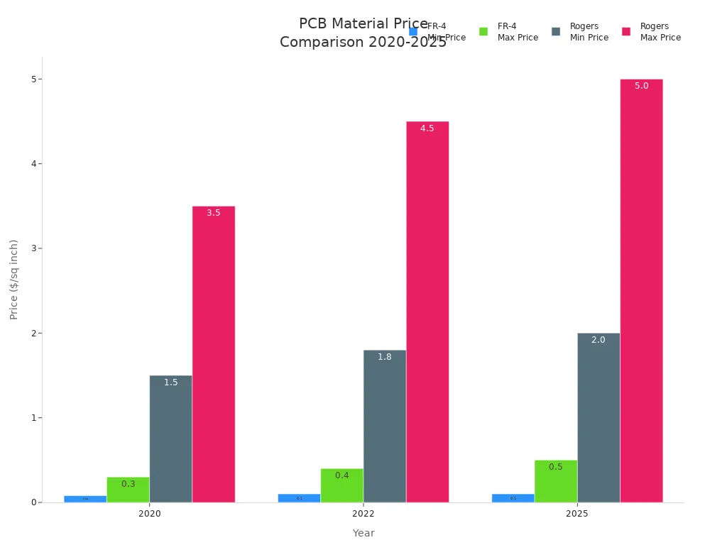
Rogers PCBs cost more, but they work better and last longer. You make sure your board meets IPC, ISO, and MIL standards before it leaves the factory.
By following these steps, you make sure your Rogers PCB is strong and reliable for advanced technology.
Ensuring Reliability in High-Frequency PCB Manufacturing
Process Control and Quality Assurance
You want every Rogers PCB to work its best. To do this, you need to check each step during manufacturing. Before starting, you look at all materials for rust and strength. Pre-baking dries out the laminates and stops problems. You use vacuum pressing to keep layers close and steady.
You also use even stack-ups and pinned tools. These steps help your PCB stay flat and not twist. Cross-section analysis looks for empty spots after lamination. First-article validation lets you test one board before making more. You track each batch with FIFO inventory and lot tracing. This keeps your materials the same.
Here is a table showing some important process control steps:
Process Control Measure | Description |
|---|---|
Pre-baking | Removes moisture from Rogers laminates. |
Vacuum-assisted pressing | Expels volatiles for stable lamination. |
Symmetric stack-ups | Maintains registration and prevents twist. |
Cross-section analysis | Confirms void-free interfaces post-lamination. |
First-article validation | Tests initial results before scaling up production. |
FIFO inventory and lot tracing | Maintains material consistency. |
You also follow strict rules from the industry. IPC-2221 gives design rules for size and electrical limits. ISO 9001 makes sure you use good steps for quality. UL checks for safety and fire resistance.
Advanced Equipment and Expertise
You need special machines and skilled workers for high-frequency boards. Special drill bits and cooling cycles stop resin smear when drilling. Plasma etching or sodium-naphthalenate treatments get the surface ready for copper. You use advanced VCP plating to keep copper the same thickness. This helps signals stay strong.
Your team uses TDR testing to check and prove impedance on each batch. This step helps you keep signal quality high. You also make test batches to set the right steps for etching and drilling. These steps cut waste and make boards more reliable.
You always use real Rogers Corporation laminates. Plasma treatment is needed for PTFE-based boards. Your team follows strict rules to find and stop problems. This careful work makes sure your PCB is strong and works well.
Tip: Always look for certifications like ISO 9001, ISO 13485, and UL 94V-0 when picking a manufacturer. These show they care about quality and safety.
How Rogers PCB Supports Smooth Tech Operation
Signal Integrity and Impedance Control
You want your devices to send clear signals. This is important for high-frequency uses. Rogers PCB helps keep signals strong and clear. It uses a material with a steady dielectric constant. This stops signals from changing as they move across the board. You also get less signal loss because of a low loss tangent. Your circuits work better with these features. Consistent electrical properties help stop crosstalk. This means signals on nearby traces do not mess up each other.
Steady dielectric constant stops signal changes.
Low loss tangent keeps signal loss low.
Less crosstalk makes signals clearer.
When you design your PCB, you must control impedance. Rogers PCB makes this easier with a low dielectric constant. You can use power planes for good signal return paths. This helps keep impedance steady. How you stack the layers in your board matters too. Putting signal layers next to reference planes helps keep the right impedance for fast signals.
Tip: Pick your material carefully and plan your layer stack-up. This helps you avoid signal problems and makes your device more reliable.
Thermal Management and Durability
You want your devices to last and work well, even when hot. Rogers PCB materials, like Rogers 5880 and RO4350B, have higher thermal conductivity than regular boards. Rogers 5880 has about 0.7 W/mK thermal conductivity. RO4350B is around 0.6 W/mK. This means your board moves heat away from hot spots faster. Better heat management lowers thermal stress. This helps your device stay reliable for a long time.
Higher thermal conductivity helps manage heat well.
Lower thermal stress makes devices last longer.
You can trust your PCB in tough places. Good heat management and strong materials keep your tech running smoothly, even in hard conditions.
You get reliable results when you pick Rogers PCBs. These boards have steady dielectric properties and low dissipation factors. This keeps your signals clear and strong. Careful lamination and special plating help your circuits work in hard places.
Engineers pick Rogers PCBs for satellite communication, automotive radar, and RF uses. They trust these boards because they are reliable and handle heat well.
Parameter | Why It Matters for Tech |
|---|---|
Dielectric Constant | Keeps signals clear |
Thermal Conductivity | Helps move heat away |
Dielectric Loss | Lowers signal loss |
Think about using Rogers PCBs for your next project if you need top performance.
FAQ
What makes Rogers PCB better for high-frequency applications?
You get stable signals with Rogers PCB. The material has a low loss tangent and steady dielectric constant. Your circuits work well at high frequencies. Engineers trust Rogers PCB for radar, 5G, and RF projects.
Can you use Rogers PCB for mixed-signal designs?
Yes, you can use Rogers PCB for mixed-signal designs. The material supports both analog and digital signals. You get less interference and clear signal paths. Your device stays reliable.
How does Rogers PCB handle heat?
Rogers PCB moves heat away from hot spots quickly. You get higher thermal conductivity than standard boards. Your device stays cool and lasts longer. This helps in tough environments.
Is Rogers PCB more expensive than FR-4?
You pay more for Rogers PCB than FR-4. The material costs more, but you get better performance and longer life. Your investment pays off in demanding applications.
What surface finishes work best with Rogers PCB?
You can use ENIG, immersion silver, or lead-free HASL. ENIG gives you a flat surface and strong soldering. Immersion silver works well for high-frequency boards. Your choice depends on your needs.
See Also
Enhancing PCB Production Yield Through Online AOI Technology
Exploring Rogers R4350B, R4003, And R5880 For RFPCB Use
Integrating Rogers Materials With TG170 For Hybrid PCB Designs
Selecting A Reliable PCB Manufacturer For Your Business Needs
Achieving Excellence In Quality Control For PCB Manufacturing