Understanding Rogers PCB Special Processing Technology in 2026
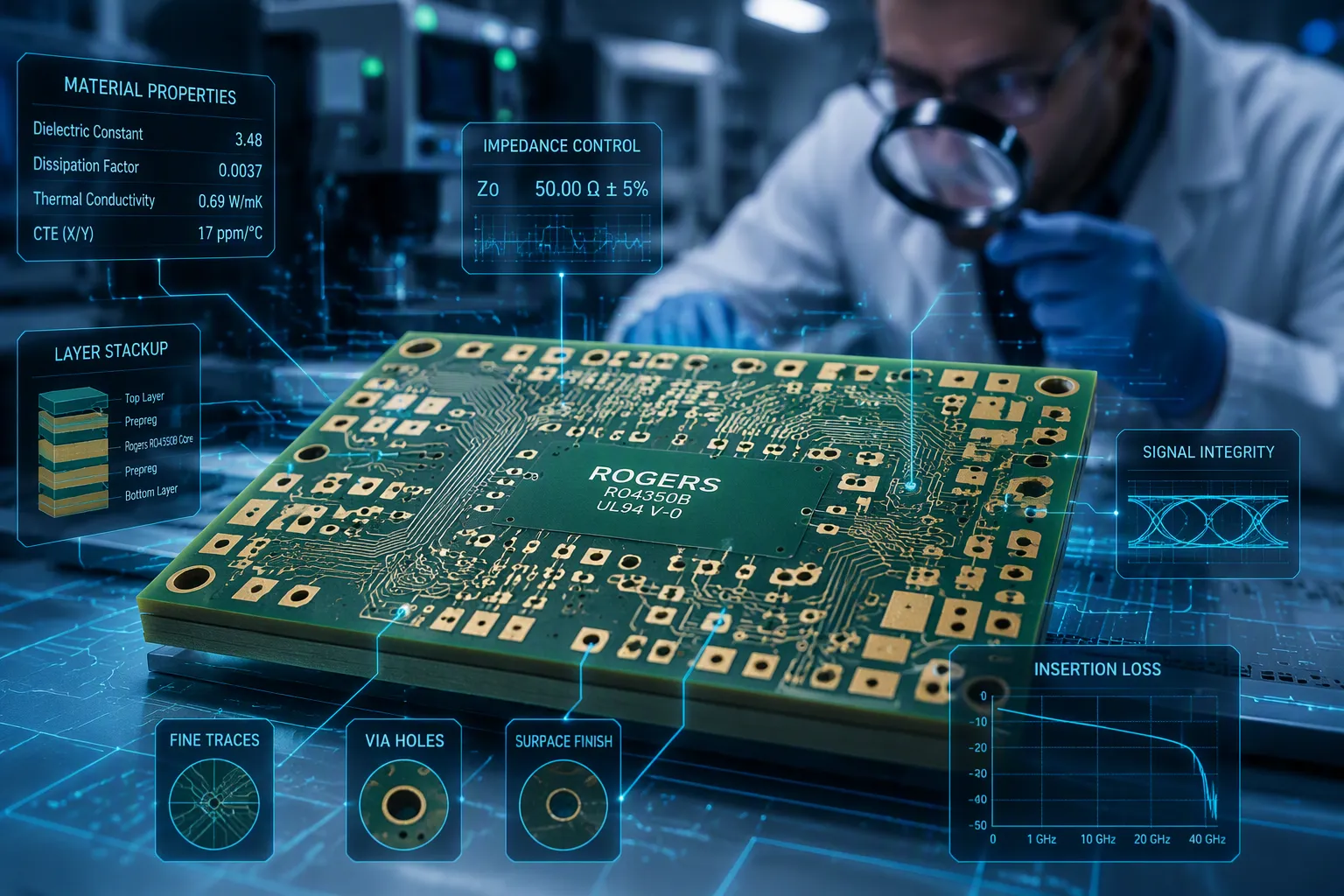
Rogers PCB special processing technology covers the fabrication steps that high-frequency laminates from Rogers Corporation demand. These steps preserve a stable dielectric constant (Dk), low signal loss, and long-term reliability. Engineers rely on them for RF, microwave, and high-speed digital circuits. A high-performance printed circuit board built on Rogers material fails quickly when shops treat it like ordinary FR-4.
Standard FR-4 workflows often break down here. Rogers laminates behave differently under heat and mechanical stress. Drill bits wear faster, resin smears appear, and bonding grows unpredictable. Rogers PCB manufacturers therefore adjust four core techniques: drilling, lamination, surface prep and finishing, and routing. Rogers PCB processing in 2026 adds tighter automation and updated design rules.
Key Takeaways
Use diamond-coated drill bits and plasma desmear to clear away resin smear from Rogers laminates.
Use Rogers 2929 bondply to attach Rogers laminates, stopping separation and preserving signal quality.
Pick immersion silver finish to lower signal loss on high-frequency Rogers boards over 5 GHz.
Use 2026 automation to track drill wear and control lamination heat for steady performance.
Why Rogers PCB Materials Need Special Processing
Unique Properties of Rogers Laminates
Rogers PCB materials use special laminated substrates. These substrates give a better dielectric constant and steady Dk over a wide frequency range. Epoxy-based FR-4 cannot match this steadiness. The Rogers RO4000 series, RO3000 series, RT/duroid series, and TMM series each aim at different high-performance uses. Their ceramic-filled and PTFE-based chemistries keep low signal loss even at microwave frequencies. This steadiness helps precise impedance control in high-speed digital and RF designs.
Thermal stability sets these laminates apart from common FR-4 too. Rogers materials keep their electrical properties across temperature swings that would shift FR-4 performance. That trait matters for high-frequency uses in radar, satellite, and automotive systems. A steady Dk means the board keeps signal integrity without constant re-tuning. Engineers pick these materials when integrity and reliability matter more than cost.
Limits of Standard FR-4 Workflows
Standard FR-4 workflows break down on Rogers PCB materials for three reasons. First, drill wear speeds up. Ceramic-filled variants are harder and more abrasive than FR-4. The table below shows the difference.
Material | Drill Bit Lifetime (holes) |
|---|---|
FR-4 (standard carbide drill) | 2,000–3,000 |
Ceramic-filled Rogers material | 1,000–1,500 |
Second, resin smear shows up. Mechanical drills at high speeds above 100 krpm make heat. That heat softens PTFE and causes 20–50 μm smear, far above IPC-6012 cleanliness specs. These Rogers PCB fabrication challenges need slower feeds and special bits.
Always check your vias after plating. Look for empty spots, thin walls, or bad sticking. These issues can cause signal attenuation and make your high-frequency circuits less reliable.
Third, bonding gets hard. PTFE and hydrocarbon surfaces resist natural adhesion. Standard FR-4 press cycles fail to form reliable bonds. Post-drill desmear leaves residues that lead to plating skips or weak barrels. Aggressive etchback loosens fillers and attacks resin near copper, compromising multilayer integrity. Plasma desmear suits CAF-sensitive designs, while chemical options scale for throughput. Drill smear often signals too much heat, so shops reduce feeds and inspect stacks for cooling.
These three hurdles explain why Rogers PCB fabrication needs dedicated process windows. A shop that runs FR-4 parameters on Rogers material will see poor plating, via failures, and peeling. The next sections cover the specific techniques that solve each problem.
Key Rogers PCB Processing Techniques
Drilling and Via Formation
Rogers PCB materials have ceramic fillers inside them, which makes them very abrasive. Regular carbide drill bits get worn out fast. A normal FR-4 bit can drill 2,000 to 3,000 holes. That same bit on ceramic-filled Rogers material might only last 1,000 to 1,500 holes. This quick wear raises costs and can lead to bad hole quality.
Resin smear causes another issue. PTFE-based Rogers laminates get soft when drilling creates heat. The soft material spreads over the hole wall and forms a layer 20 to 50 micrometers thick. This is thicker than IPC-6012 cleanliness specs allow. The layer stops copper plating from sticking properly. Bad via connections and weaker signals are the result.
Picking the right drill bit is very important. Diamond-coated bits can handle the abrasion from ceramic fillers. Special flute shapes help clear away debris. These features make bits last longer and keep hole quality good. Peck drilling cycles remove debris and cool the bit between steps.
Plasma desmear is a key step in via formation. This method uses ionized gas to clean and activate hole walls. It removes resin smear and gets surfaces ready for strong copper bonding. This step is a must for PTFE-based Rogers materials.
High-precision drilling keeps vias lined up correctly and layers connected. Via shielding puts via fences around high-speed traces. This stops lateral EMI leakage and keeps energy inside transmission lines. Placing thermal vias under high-power components stops overheating and keeps signal quality steady.
Lamination and Bonding
Standard FR-4 press cycles do not work with Rogers materials. PTFE and hydrocarbon surfaces do not stick naturally. Rogers laminates and copper expand at different rates when they cool, which creates stress. These things cause delamination and weak multilayer structures.
A Rogers PCB needs lamination parameters that are carefully controlled. The temperature must rise much more slowly than in FR-4 cycles. The pressure profile needs changes to match how the material flows. Controlled cooling rates stop warping and keep dimensions stable.
Bonding films are a must for good lamination. Rogers 2929 bondply is made just for PTFE hybrids like RO3003 and RT5880. This bondply has a matching dielectric constant and thermal expansion rate. It connects different material types together. Standard FR4 prepreg cannot work at Rogers material interfaces. It causes impedance discontinuities and weak adhesion.
RO3003 and RO3003G2 laminates need both PTFE plasma activation and Rogers 2929 bondply for hybrid stack-ups. This combo gives a matching interface that stops signal integrity problems and makes lamination reliable in mixed-material builds.
Hybrid stack-ups save a lot of money. Using Rogers for high-frequency layers and FR-4 for power and ground layers cuts cost by 30 to 50 percent. This method keeps performance while using pricey materials only where they are needed. Precise impedance control across different dielectric materials is a must.
Ground plane continuity is still very important. A solid, unbroken reference plane under RF traces gives low-impedance return paths and stable impedance. Via design and stitching link ground planes across layers to lower ground impedance. A Rogers PCB must keep proper thermal stability. The lamination process keeps thermal stability for low signal loss when parameters are right. Keeping thermal stability intact keeps the dielectric constant steady across the operating temperature range.
Surface Prep, Finishing, and Routing
Surface Preparation and Finishing
Surface prep determines if copper sticks to a rogers pcb laminate. PTFE and hydrocarbon surfaces fight against sticking. Plasma treatment fixes this without harsh chemicals. It wakes up the surface and boosts bond strength. A vacuum plasma process gives exact, controlled, and even surface changes. Shops adjust gas flow, power, and time to fit each material.
Plasma treatment wins over chemical etching in several ways. It makes no dangerous liquid waste. Chemical methods with sodium ammonia or sodium naphthalene create a lot of harmful liquid waste. Those wet chemicals hurt the environment and the workers who touch them. Plasma processing skips this danger completely.
Benefit | Plasma Treatment | Chemical Etching |
|---|---|---|
Environmental Impact | No hazardous liquid waste | Substantial hazardous liquid waste |
Process Control | Gas flow, power, duration finely tuned | Limited control |
Repeatability | Highly consistent | Inconsistent activation |
Post-treatment | No extensive rinsing | Extensive rinsing required |
Finishing also changes signal loss. On 10 mil RO4350B with a Df of 0.0037 at 10 GHz, a 50 Ω microstrip runs about 0.35 dB per inch with immersion silver. ENIG raises that to around 0.45 dB per inch. Immersion silver is the lower-loss finish above about 5 GHz. Tests show it can cut signal loss by up to 20% compared to ENIG near 10 GHz. For high-frequency rogers pcb designs, immersion silver is the best choice.
Routing and Profiling
Routing and profiling carry mechanical risks. Ceramic-filled laminates break easily. Fiber pull-out and burring show up when tools cut too fast. Dimensional drift appears when heat builds during depaneling. These flaws shift trace positions and break exact impedance control.
Shops use sharp router bits with steady feed rates. They slow down spindle speeds to limit heat. They also use good support fixtures to keep the board flat. These steps keep edges clean and sizes stable. A rogers pcb keeps thermal stability through routing when shops handle heat and tool wear. Careful depaneling protects the board and keeps signal integrity.
2026 Advancements and Best Practices
Automation and Process Control
Rogers Corporation puts out material selection and building guides that shape how shops make high-frequency boards. In 2026, rogers pcb makers use automated drilling and lamination systems to keep tight process windows. These systems watch drill wear in real time and change feeds before hole quality drops. Automated press controls follow the slow temperature ramps that PTFE and hydrocarbon laminates need. This care protects thermal stability on every panel.
Tighter process control also cuts down on human error. Inline inspection catches resin smear and plating voids before boards move on. Shops log plasma treatment settings for each material type, so results stay repeatable. A rogers pcb built under these controls keeps its dielectric constant steady and avoids the bonding failures that happen with manual workflows.
Updated Design Guidelines
Modern design rules for high-frequency boards focus on ground integrity. Via stitching spacing must stay below one-twentieth of the operating wavelength to make an effective ground fence. That equals about 6 mm at 2.4 GHz and 1.5 mm at 10 GHz. When the wavelength grows too small for that spacing, designers may relax to one-tenth of the wavelength.
Keep a continuous ground plane beneath RF traces.
Avoid slots or splits in the ground plane, because they force return currents to detour and cause reflections and EMI.
Place ground-stitching vias near signal vias at layer transitions to hold a low-impedance return path.
Add multiple ground vias around RF components, connectors, and shields.
Use a solid ground fill instead of a hatched pattern for better shielding.
These rules support precise impedance control and clean high-speed signal behavior. Designers should also connect top-layer ground fills to inner layers with vias spaced no farther than one-twentieth of the signal wavelength. Isolated ground islands need vias or copper bridges back to the main plane. Rogers Corporation guidance on material selection and design considerations ties these practices together for reliable RF and microwave performance.
Rogers materials need special processing because their dielectric stability, thermal behavior, and mechanical hardness are very different from FR-4. Ceramic-filled and PTFE laminates keep a steady Dk and low signal loss, but they wear out drill bits faster and resist natural adhesion. Four techniques protect signal integrity and reliability. Drilling with diamond-coated bits and plasma desmear stops resin smear. Controlled lamination with Rogers 2929 bondply prevents delamination. Plasma surface prep and immersion silver finishing reduce loss. Careful routing avoids fiber pull-out and dimensional drift. A rogers pcb built under 2026 automation and updated design rules avoids drill wear, smear, and bonding failures. Following these practices keeps a rogers pcb reliable in 5G mmWave use, where materials like RO3003 stay stable to 77 GHz.
FAQ
Why do standard FR-4 drill bits wear out faster on Rogers laminates?
Ceramic fillers inside Rogers materials make them rough and abrasive. A standard carbide bit can drill 2,000 to 3,000 holes in FR-4. That same bit only lasts 1,000 to 1,500 holes in ceramic-filled Rogers material. Shops switch to diamond-coated bits to handle the wear.
What causes resin smear during Rogers PCB drilling?
High spindle speeds above 100 krpm create heat. That heat makes PTFE-based laminates soft. The soft material spreads across the hole wall and forms a layer 20 to 50 μm thick. This is more than IPC-6012 cleanliness specs allow. Plasma desmear removes the smear before plating.
Why can't FR-4 prepreg bond Rogers laminates in multilayer stack-ups?
PTFE and hydrocarbon surfaces do not stick naturally. FR-4 prepreg cannot make a strong bond at these interfaces. It also causes impedance discontinuities. Shops use Rogers 2929 bondply instead. This bondply matches the dielectric constant and thermal expansion rate of PTFE hybrids like RO3003 and RT5880.
Which surface finish lowers signal loss on high-frequency Rogers boards?
Immersion silver gives the lowest loss above about 5 GHz. On 10 mil RO4350B, a 50 Ω microstrip loses about 0.35 dB per inch with immersion silver. ENIG raises that to around 0.45 dB per inch. Tests show immersion silver cuts loss by up to 20% near 10 GHz.
How do rogers pcb manufacturers control quality in 2026?
Shops use automated drilling and lamination systems. These systems track drill wear in real time and adjust feeds before hole quality drops. Automated press controls follow slow temperature ramps for PTFE laminates. Inline inspection catches resin smear and plating voids early. These steps keep the dielectric constant steady on every panel.
See Also
Exploring Properties And Applications Of Rogers R4350B R4003 R5880 RFPCBs
Overview Of The PCB Manufacturing Process And Key Steps
Techniques To Combine Rogers Material And TG170 For Hybrid PCBs
Comprehensive Guide To Production Technology For Heavy Copper Multilayer PCBs
Applications Of Multilayer PCBs In Diverse Industrial Sectors
