Why Rogers PCB is Essential for High-Frequency Industrial Equipment
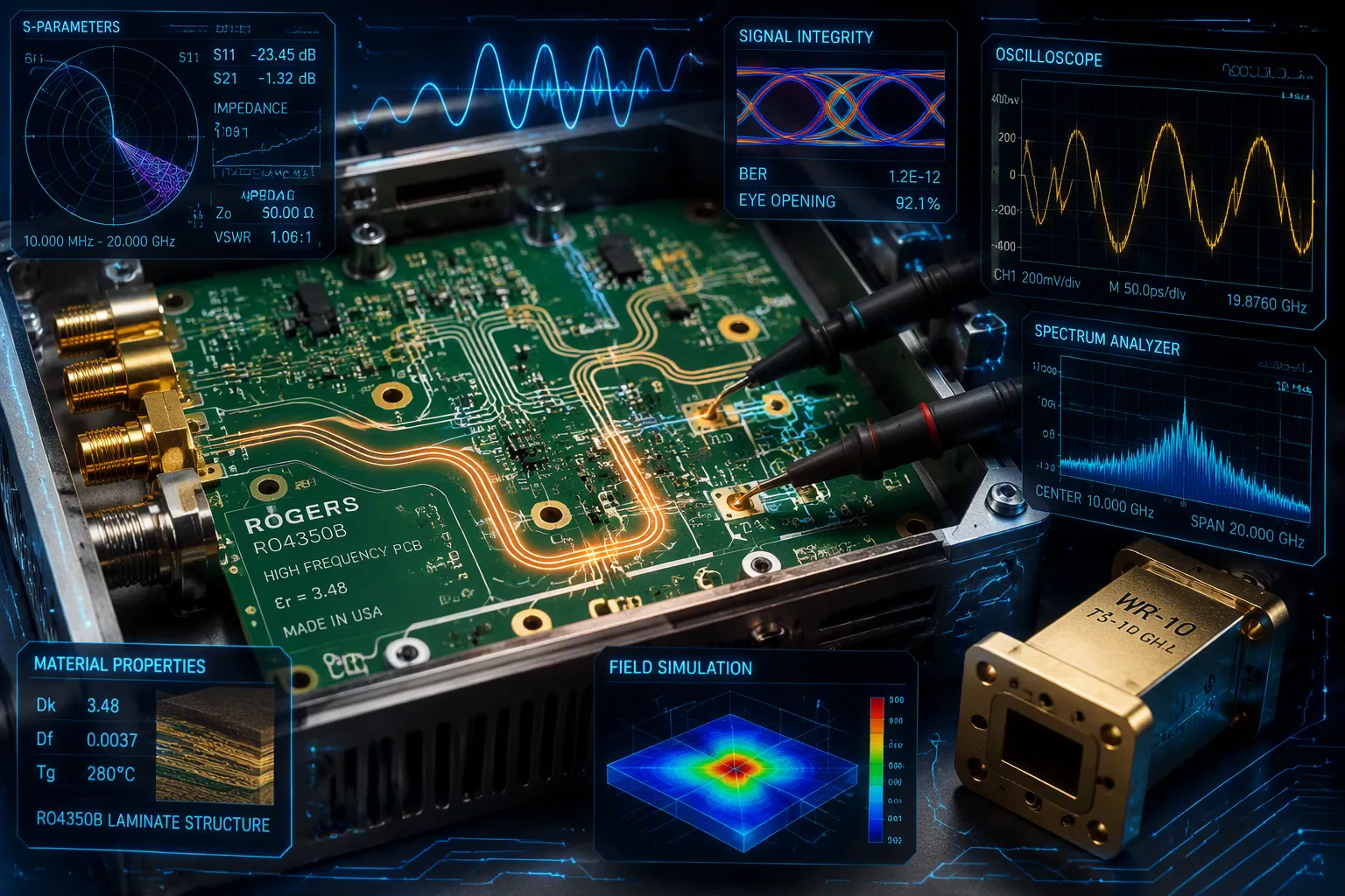
Picture a radar unit at an industrial site. Its signal suddenly distorts. Readings become unreliable. Production halts. The culprit? Often the PCB material itself.
The root cause is frequently the board substrate. Rogers PCB solves this problem. It offers low signal loss and a stable dielectric constant. These properties keep high-frequency equipment performing accurately.
Yes, Rogers PCB costs more. You might pay 3x-5x more per square inch than FR4. Yet that premium buys reliability. Lower insertion loss means smaller components. Better thermal conductivity reduces heatsink needs. Your total system cost can drop.
For rf applications, material choice determines success. Rogers delivers consistent performance where FR4 fails.
Key Takeaways
Rogers PCB materials cut signal loss and keep the dielectric constant stable, so high-frequency performance is reliable.
FR4 stops working well above 1 GHz because it loses too much signal and its Dk is not steady, which leads to mistakes and unreliable machines.
Choose RO4003C for the least loss of signal, or RO4350B for better heat handling and fire safety.
Rogers PCB costs more at first, but it saves money by cutting down on extra parts and failures in the field.
Choose a maker that knows Rogers materials well to get good quality and performance.
Why FR4 Fails in High-Frequency Equipment
FR4 has been used in electronics for many years. It works fine for simple digital boards and low-speed circuits. But when you go above 1 GHz, FR4's problems become too big to ignore. Two key material traits cause the trouble: dissipation factor and dielectric constant stability.
High Signal Loss and Attenuation
The dissipation factor (Df) shows how much energy turns into heat as a signal moves through the material. FR4 has a Df of about 0.02. High-frequency materials like Rogers PCB laminates reach Df values between 0.001 and 0.005. That gap matters a lot at high frequencies.
Material | Loss Tangent (Df) |
|---|---|
FR4 | ~0.02 |
High-frequency materials | 0.001–0.005 |
Think about a 2.4 GHz industrial wireless system. A short trace on FR4 can lose up to 30% of its signal power. The same trace on a Rogers PCB loses less than 5%. You can see the issue clearly. This signal loss means your signal arrives weak and distorted. The receiver struggles to read the data. Communication errors pile up. Production equipment gets wrong commands. The whole system becomes unreliable.
This signal loss also makes you add amplifiers and boosters. Those parts use power, create heat, and take up room. They raise your bill of materials. They add new failure points. A material with lower Df removes the need for much of that extra circuitry. You save money on parts and make your design simpler.
Unstable Dielectric Constant (Dk)
The dielectric constant (Dk) controls how fast signals travel through the material. It also affects impedance matching. FR4's Dk changes with frequency. At 1 MHz, you see a Dk around 4.5. At 1 GHz, it drops to roughly 4.0–4.2. At 10 GHz, it falls further to about 3.9–4.0.
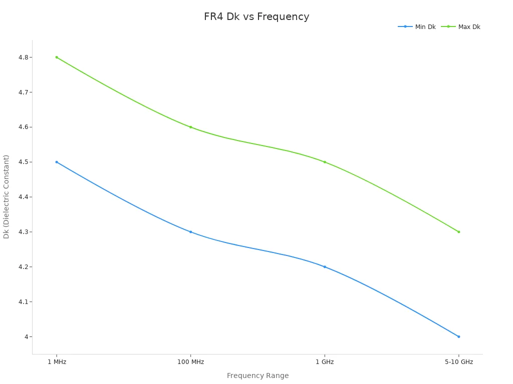
Temperature makes things worse. FR4's Dk shifts about 200 ppm per degree Celsius. Over a 60°C temperature swing, you see roughly 1.2% variation. Even a 1% shift in Dk causes timing skew in tightly matched differential pairs. Your impedance calculations become guesses instead of certainties. You cannot predict how your board will act in the field.
The inner structure of FR4 adds another issue. Glass fiber has a Dk near 6.2. Epoxy resin has a Dk near 3.2. These two materials weave together unevenly across the board. Different traces see different effective Dk values. You can get up to ±5% impedance variation across a single board. Differential pairs suffer intra-pair skew. Signal reflections appear at every impedance mismatch. Your high-speed links degrade with each reflection.
For precision industrial equipment, these variations are not acceptable. A radar unit needs steady phase relationships. A wireless sensor needs predictable timing. An RF power amplifier needs exact impedance matching. FR4 cannot deliver any of these reliably. You need a material you can count on.
Rogers PCB materials fix this problem. They offer a stable dielectric constant across frequency and temperature. Your impedance calculations hold true. Your signals arrive intact. Your equipment works as designed. You remove the guesswork from your design process.
The choice is clear. For high-frequency industrial uses, FR4's cost advantage disappears when you factor in performance failures, debugging time, and field returns. A Rogers PCB gives you the consistency your equipment needs. Your RF systems deserve better than a material that cannot keep up.
Key Advantages of Rogers PCB for Signal Integrity
Rogers PCB materials stand apart from standard laminates because manufacturers engineer them specifically for RF and microwave work. You get predictable electrical behavior that FR4 cannot match. Two core properties drive this performance: low signal loss and a stable dielectric constant.
Low Signal Loss and Consistent Dk
Signal integrity starts with the dissipation factor. Rogers PCB laminates achieve remarkably low Df values. The table below shows two popular grades:
Parameter | RO4350B | RO4003C |
|---|---|---|
Df @ 10 GHz | 0.0037 | 0.0027 |
Dk @ 10 GHz | 3.48 ±0.05 | 3.55 ±0.05 |
Max Freq. Recommendation | 77 GHz+ | 77 GHz+ |
Compare those numbers to FR4's Df of roughly 0.02. You see a five-to-tenfold improvement. Less energy converts to heat. More signal reaches its destination intact.
Dielectric constant stability: At high frequencies, standard FR4 loses power rapidly. Rogers materials maintain consistent electrical properties. You achieve easier impedance matching and reduced signal loss in demanding systems.
Insertion loss reduction: Conventional boards absorb excessive power. Rogers PCBs reduce this energy loss, particularly in mmWave applications. Your signal integrity stays preserved at high speeds.
Stability with Temperature: A stable Dk over temperature variations prevents signal phase shifts and impedance changes as the operating environment fluctuates.
The dielectric constant of Rogers materials remains steady across frequency and temperature. You can calculate impedance with confidence. Your high-frequency designs perform as simulated, not as guessed. These high-frequency pcb materials give you repeatable results batch after batch.
Superior Thermal and Mechanical Stability
High-frequency circuits generate substantial heat. That heat can degrade performance and shorten lifespan. Rogers laminates handle this challenge effectively.
Property | FR4 (W/m-K) | Rogers (W/m-K) |
|---|---|---|
Thermal Conductivity | 0.1 to 0.3 | 0.69 to 1.7 |
This high thermal conductivity means heat spreads quickly through the board. You reduce hot spots. You extend component life. You may even eliminate bulky heatsinks from your design.
Mechanical stability matters just as much. Rogers materials maintain their shape under temperature swings.
Property | Documented Value | Relevance to Long-Term Reliability |
|---|---|---|
CTE (XY) | 8–20 ppm/°C | Maintains dimensional stability during temperature fluctuations, preventing warping or delamination |
Moisture Absorption | 0.02% | Prevents degradation and electrical failure in high-humidity industrial environments |
Tensile Strength | >16,000 psi (110 MPa) | Withstands mechanical stress, maintaining structural integrity and circuit stability |
Glass Transition Temp (Tg) | 280°C | Ensures material retains mechanical properties at elevated operating temperatures |
Decomposition Temp (Td) | 340°C | Provides a high safety margin against thermal degradation over extended service life |
Rogers materials hold up under extreme heat, humidity, and mechanical stress, making them ideal for outdoor or industrial applications where long-term reliability is critical.
The low moisture absorption gives you excellent moisture resistance. The material resists chemical attack, providing chemical stability in harsh environments. Thermal stability means your board keeps its shape. Vias stay intact. Pads remain attached. Your signal paths stay consistent.
For RF systems in industrial settings, these properties translate directly to reliability. You get fewer field failures. You spend less time on troubleshooting. Your equipment keeps working.
While the dielectric constant is typically considered a stable property, it can be influenced by environmental factors such as temperature, humidity, and exposure to certain chemicals or contaminants. Rogers PCB materials are designed to maintain consistent dielectric constant values over a wide range of operating conditions, ensuring reliable and repeatable performance.
The combination of low signal loss, stable dielectric constant, and superior thermal management makes Rogers PCB the right choice for high-frequency applications. You invest in predictability. You invest in performance. You invest in equipment that works when you need it.
Choosing the Right Rogers PCB Materials
Picking the right material for your high-frequency design takes careful thought. You must match the material's properties to your operating frequency, power level, and environment. Rogers PCB makes several grades for different needs. Two popular choices are RO4003C and RO4350B. These Rogers pcb materials give steady performance where standard laminates fail.
Matching Material to Frequency and Power Needs
Your operating frequency is the first thing to think about. RO4350B keeps a stable dielectric constant of 3.48 and a dissipation factor of 0.002 from 100 MHz to 10 GHz. This stability keeps performance steady in high-frequency uses. Power level matters just as much. At 800 MHz, RO4350B handled about 250W for a +77°C temperature rise. Standard FR4 reached +75°C at only 40W. Environmental conditions also guide your choice. RO4350B absorbs very little moisture at 0.06%. This low absorption protects your dielectric properties in humid places. The material also has low CTE values for dimensional stability. These properties make Rogers laminates ideal for outdoor industrial equipment.
Selection Criterion | What Rogers Materials Deliver |
|---|---|
Operating Frequency | Stable Dk of 3.48 and Df of 0.002 from 100 MHz to 10 GHz |
Power Level | Thermal conductivity up to 0.69 W/mK supports high-power circuits |
Environmental Conditions | Moisture absorption of 0.06%, low CTE, high Tg for reliability |
Balancing Cost and Performance with Popular Grades
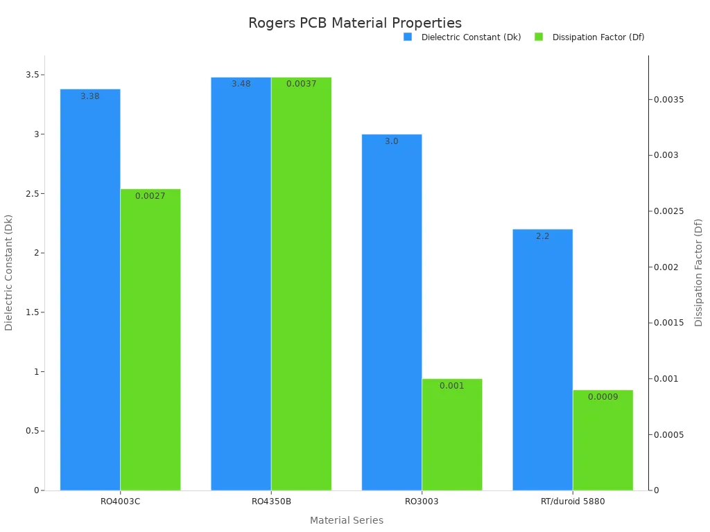
RO4003C and RO4350B offer different trade-offs. RO4003C has a lower dissipation factor of 0.0027 at 10 GHz. This means lower signal loss for demanding RF circuits. RO4350B has a Df of 0.0037 at 10 GHz, which is about 37% higher. However, RO4350B offers better thermal stability. Its Z-axis CTE is 32 ppm/°C versus 46 ppm/°C for RO4003C. This reduces mechanical stress on through-holes. RO4350B also carries a UL 94 V-0 flame rating. RO4003C does not have this rating. For industrial equipment that must pass fire safety regulations, RO4350B is the clear choice.
Property | RO4003C | RO4350B |
|---|---|---|
Dissipation Factor at 10 GHz | 0.0027 | 0.0037 |
Thermal Conductivity | 0.71 W/m·K | 0.69 W/m·K |
UL 94 V-0 Rating | Not rated | Rated |
For high-frequency designs where signal loss is critical, choose RO4003C. For applications that need better thermal reliability and regulatory compliance, pick RO4350B. Both materials offer high thermal conductivity compared to FR4. They support standard FR4 processing, which keeps fabrication costs manageable. High-frequency pcb materials like these Rogers laminates ensure your system performs as designed. Your choice of Rogers pcb grade affects overall system performance. The right Rogers pcb grade makes your high-frequency designs work reliably in RF systems.
Fabrication Challenges and Manufacturer Selection for Rogers PCB
Rogers PCB materials act differently than FR4 during fabrication. You cannot just send your design to any board shop and expect good results. The material's special properties need specific processes and equipment.
Unique Processing Requirements for Rogers Materials
Rogers laminates with PTFE or ceramic fillers are more brittle than FR4. They crack or chip during cutting and shaping. Regular milling can damage the board edges. Laser cutting gives better precision for tight tolerances. You also need to adjust machine speed and pressure to lower damage risk.
Drilling brings another challenge. Ceramic-filled Rogers materials are harder and more abrasive than FR4. Standard drill bits wear out fast. You need special drill bits with optimized spindle speed and feed rate. Peck drilling cycles help remove debris and stop heat buildup. The table below shows recommended routing parameters:
Parameter | Recommended Value |
|---|---|
Internal corner radius (router bit limit) | Min. R0.5 mm |
External corner radius (small boards) | R0.5–R1.0 mm |
External corner radius (standard designs) | R1.0–R2.0 mm |
Edge clearance | 0.3–0.5 mm |
Rounded corners reduce stress concentration and stop chipping during routing.
PTFE-based materials need plasma treatment after drilling. Standard chemical desmearing cannot clean the hole walls well. Plasma treatment uses ionized gas to make a clean surface for reliable copper bonding.
Key Criteria for Vetting a Qualified Manufacturer
Your manufacturer must understand high-frequency pcb materials. Bad handling leads to impedance changes and signal loss. Ask about their experience with Rogers laminates specifically.
Look for these capabilities:
Impedance verification using sample coupons to confirm high-frequency performance
Automated Optical Inspection (AOI) to find manufacturing defects
X-ray inspection for internal layer alignment issues
100% electrical testing for continuity and isolation
Final quality inspection including dimensional and visual checks
A qualified manufacturer also offers design help. They assist you in picking the right Rogers pcb materials for your application. They source genuine laminates from Rogers Corporation. They control layer alignment and copper cladding precisely.
Rogers materials, especially those containing PTFE, are chemically inert. Standard chemical desmearing cannot effectively clean or 'activate' the hole walls for plating. Plasma treatment uses ionized gas to ensure a clean surface, which is critical for reliable copper bonding.
Ask for their track record in industrial high-frequency applications. Request references from similar projects. Verify their testing equipment and procedures. A manufacturer with proven experience delivers boards that meet your dielectric constant and impedance requirements consistently.
Rogers PCB is an important choice for engineers, not just about picking a material. You need it for high-frequency industrial equipment to work right and last longer. FR4 fails because it loses too much signal and has unstable Dk (dielectric constant). Rogers materials give better signal quality and heat stability. Special grades like RO4003C and RO4350B give you the right performance. A good manufacturing partner makes sure your boards work as planned.
The need for high-frequency technology is growing fast. The market for these systems is expected to grow from USD 10.4 billion in 2026 to USD 15.3 billion by 2031, a yearly growth of 8.0%. This growth covers industrial automation, 5G, and IoT. Rogers PCB is the base for this new technology.
Even though the first cost is 3 to 5 times higher than FR4, the total cost over time is often lower. Less signal loss means you need fewer amplifiers. Better heat stability makes the product last longer and cuts down on failures in the field.
Look at your current projects. Ask yourself: is the material you choose holding back your equipment's performance and reliability?
FAQ
Can I use Rogers PCB for every board in my design?
You can, but you don't have to. Rogers PCB is best for high-frequency circuits. For power supplies or simple digital logic, FR4 still works fine. Many designers use hybrid boards. They mix Rogers layers for RF sections and FR4 for the rest. This method balances cost and performance.
How do I know if my application needs Rogers PCB materials?
Check your operating frequency. If your circuit runs above 1 GHz, you need low-loss materials. Also think about your signal integrity needs. If timing accuracy and impedance matching matter, Rogers delivers. Ask yourself: can your system handle 30% signal loss? If not, you need Rogers.
Can any PCB manufacturer fabricate Rogers boards?
No. Rogers PCB materials need special handling. The material is more brittle than FR4. Standard drilling and routing can crack or chip it. You need a manufacturer with experience in high-frequency laminates. They must have proper drill bits, plasma treatment equipment, and impedance testing capability.
Does Rogers PCB cost more than FR4?
Yes, the material costs 3 to 5 times more per square inch. But think about the total system cost. Lower signal loss means fewer amplifiers. Better thermal performance reduces heatsink needs. Your overall bill of materials can actually go down. The reliability savings in the field also add up.
See Also
Key Manufacturing Capabilities And Design Considerations For High Frequency RF PCBs
Rogers R4350B R4003 And R5880 Properties And Applications For RFPCBs
Exploring Diverse Applications Of Multilayer PCBs Across Various Industries
Rigid Flex PCB Applications In Industrial Control And Medical Equipment Systems
Understanding High Speed PCBs And Their Essential Characteristics And Uses
