Rogers PCB vs Other High-Frequency Materials
Picking a high-frequency PCB material means making a tough choice. Rogers PCB materials give steady dielectric properties at high frequencies, but they cost more than standard FR4. They also go head-to-head with PTFE/Teflon and Taconic for ultra-low loss. The global market for these materials hit USD 1,288.0 million in 2025. It is expected to grow 8.9% each year through 2032. This growth shows the rising need for reliable high-frequency performance in radar and telecommunications. Signal integrity becomes critical above 1 GHz, where standard materials like FR4 show high loss. Rogers PCB meets these needs, but engineers must weigh electrical, thermal, and cost factors to choose the right printed circuit board material.
Key Takeaways
Use Rogers PCB for frequencies over 6 GHz. It keeps signals strong and stable.
Rogers materials cost more than FR4. But they give you less signal loss and consistent performance.
PTFE gives very low signal loss. Rogers adds ceramic fillers so it holds its shape better and is easier to work with.
Taconic helps save money for high-frequency designs. Rogers provides more stable performance at different temperatures.
Pick your material based on what you need: frequency, loss budget, heat, and cost.
Material Comparison: Key Properties
Dielectric Constant (Dk) and Signal Integrity
The dielectric constant, or Dk, tells how well a material holds electrical energy. This number directly changes how a circuit controls electrical flow. A steady Dk keeps impedance stable at all frequencies. That steadiness helps keep signal integrity in high-frequency designs.
Rogers PCB materials use ceramic-based mixes instead of standard epoxy resin. This blend gives a steady dielectric constant over many frequencies. For example, Rogers RO4350B is a ceramic-filled laminate. Its Dk is 3.48 ± 0.05 at 10 GHz. This number barely changes from DC to over 40 GHz.
Material | Dielectric Constant (Dk) | Frequency-Dependent Behavior | Frequency Range |
|---|---|---|---|
Rogers RO4350B | 3.48 ± 0.05 (at 10 GHz) | Tightly controlled and fairly stable across frequencies | DC to 40+ GHz |
Standard FR4 | 4.2–4.8 | Varies widely with frequency, temperature, and humidity | DC to 3 GHz |
Standard FR4 acts differently. Its Dk moves between 4.2 and 4.8. Heat and moisture also change this number. Those changes cause unexpected phase shifts in RF circuits. Engineers who want steady performance above 1 GHz often use Rogers laminates because of this.
Dissipation Factor (Df) and Insertion Loss
The dissipation factor, or Df, is also called loss tangent. It measures how much energy a material turns into heat. A low Df means less signal loss. This matters most above 1 GHz, where signal loss grows fast.
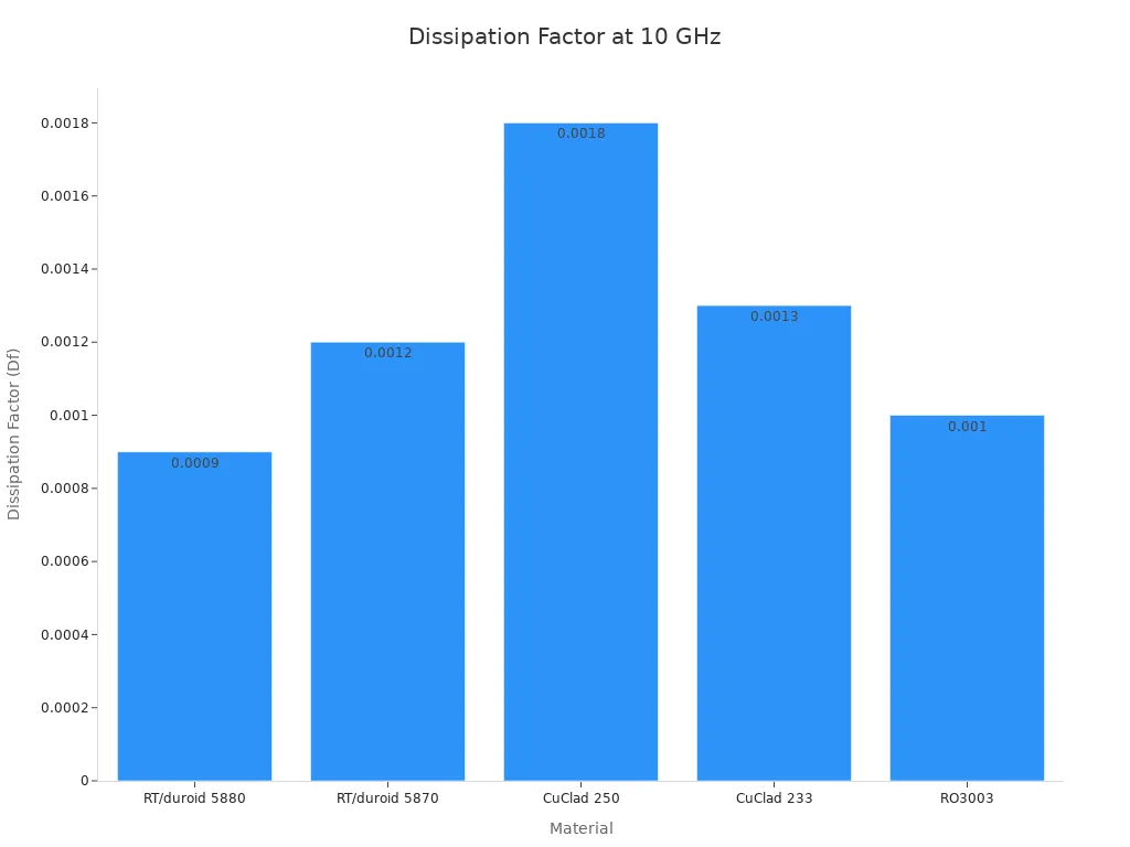
Rogers PCB materials give low loss through careful chemistry. Rogers RO3003 has a Df of 0.0010 at 10 GHz. That number is as good as pure PTFE materials. RT/duroid 5880, a PTFE laminate, gets 0.0009 at 10 GHz. Standard FR4 is much higher at 0.015–0.020.
Material | Dk | Df at 10 GHz |
|---|---|---|
FR-4 Standard | 4.2–4.5 | 0.015–0.020 |
Rogers RO4350B | 3.48 | 0.0037 |
Rogers RO3003 | 3.00 | 0.0010 |
PTFE (RT/duroid 5880) | 2.20 | 0.0009 |
RO3003 has a dissipation factor of only 0.0010 at 10 GHz. It matches pure PTFE materials but has better size stability and lower cost.
Looking at these properties shows why material choice affects signal loss. A high Df turns signal energy into heat. This loss gets worse as frequency goes up. For any high-frequency PCB material, low Df is not a choice. It is the base of low signal loss.
Rogers PCB vs FR4
Electrical Performance
The material comparison between Rogers PCB and FR4 starts with dielectric behavior. Rogers PCB materials keep a steady dielectric constant across a wide frequency range. FR4 does not. Standard FR4 moves from 4.2 to 4.8 in Dk, about a ±0.6 drift. Rogers 4350B stays at 3.48 ±0.05. That tight range protects signal integrity because impedance stays predictable.
The dissipation factor shows an even clearer difference. Lower Df means less RF energy becomes heat, which lowers insertion loss and makes transmission distance longer.
Material | Typical Df (dissipation factor) |
|---|---|
Standard FR4 | 0.018–0.025 |
High-speed FR4 | 0.010–0.015 |
Rogers RO4003C | 0.0027 |
Rogers RO4350B | 0.0037 |
Below 3 GHz, FR4 still works. One case saw 340 WiFi boards run on Shengyi S1000-2M at 2.4 GHz with Dk drift within 0.2 and zero field returns. Between 3 and 6 GHz, the loss budget decides. FR4 loss tangent at 5 GHz reaches 0.020, while Rogers 4350B sits at 0.0037. Above 6 GHz, Rogers becomes mandatory.
Every dB of insertion loss lost in the dielectric must be compensated elsewhere — bigger power amplifier, higher-gain LNA, tighter noise figure. On a long trace at 5+ GHz, FR-4’s loss tangent can quietly consume a link budget that was never sized to absorb it.
Cost and Manufacturability
Cost separates these two materials just as clearly as loss does. Rogers PCB costs roughly $5–$15 per square inch. Budget-friendly FR-4 costs a small fraction of that. A designer pays for the ceramic-filled chemistry that delivers stable Dk and low loss.
Manufacturability favors FR4 in most shops. FR4 processes like standard epoxy laminate, so any fabricator can handle it. Rogers laminates need tighter drilling and lamination control. PTFE-based options demand even more care. That gap explains why FR4 still dominates general electronics. Rogers wins in RF and high-frequency systems where a high-frequency pcb material must hold performance across the band.
Rogers PCB Materials vs PTFE/Teflon
Ultra-Low Loss Performance
PTFE, or Teflon, has been the top choice for very low signal loss in high-frequency uses for a long time. Rogers PCB materials now compete with that top spot. A comparison at 10 GHz shows how close the two groups are. Rogers RT/duroid 5880 has a loss tangent of 0.0009. The PTFE-based RT/duroid 5870 measures 0.0012. Taconic's TLY-5, a PTFE and woven glass blend, also reaches 0.0009.
Material | Loss Tangent (Dissipation Factor) at 10 GHz |
|---|---|
Rogers RT/duroid 5880 | 0.0009 |
Rogers RT/duroid 5870 (PTFE-based) | 0.0012 |
Taconic TLY-5 (PTFE/woven glass) | 0.0009 |
"Lowest electrical loss for reinforced PTFE material"
These numbers are important at mmWave frequencies. Signal loss goes up as frequency gets higher, so a low dissipation factor guards the link budget. Rogers PCB materials give low dielectric loss that matches pure PTFE. Designers get ultra-low loss without losing other features.
Thermal and Mechanical Differences
Thermal stability sets Rogers PCB materials apart from standard PTFE. Rogers CLTE laminates are PTFE-based and built for low thermal expansion. Their X, Y, and Z CTE values are 10, 12, and 34 ppm/°C. The RO4350B laminate shows X, Y, and Z values of 11, 14, and 46 ppm/°C.
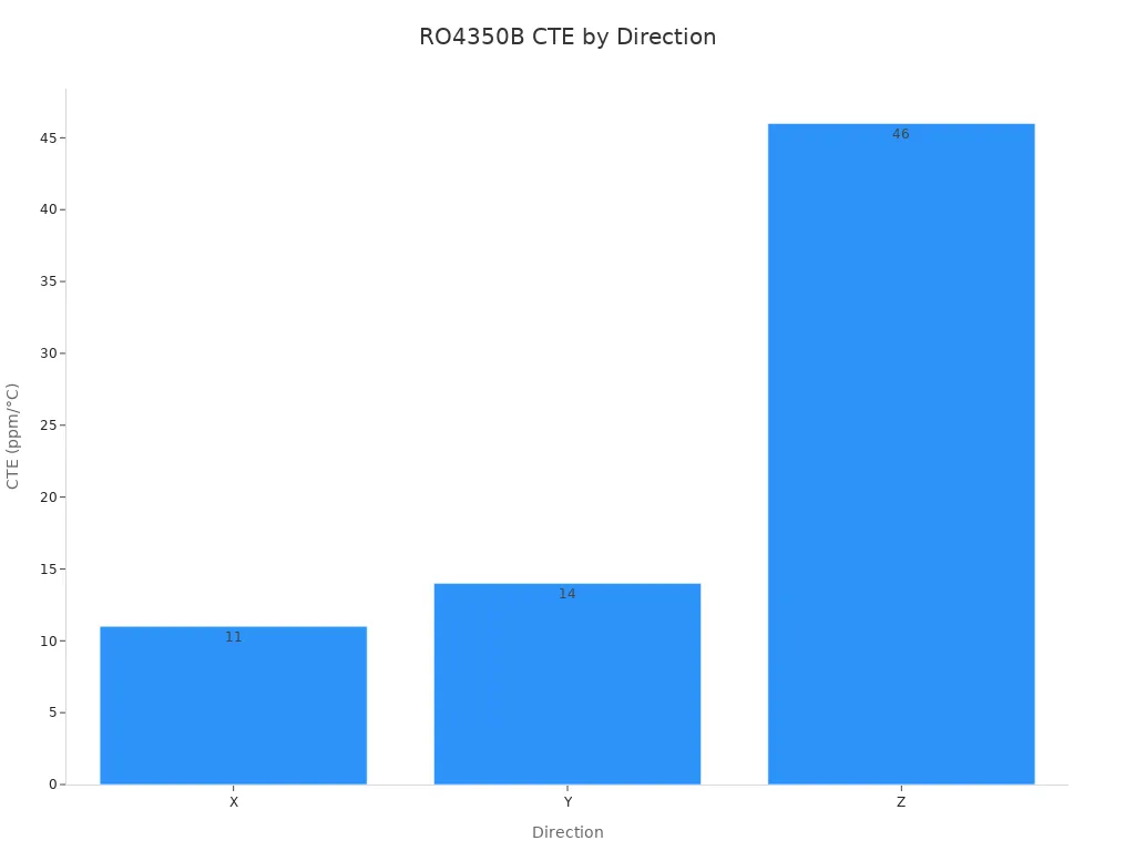
This dimensional stability works well for radar, satellite, and precision rf uses. PTFE by itself tends to creep and shift when heated. Rogers mixes ceramic fillers into the PTFE matrix to keep its shape.
Processing difficulty is still a trade-off. Pure PTFE is soft and can cold flow during drilling. It needs special tooling and careful lamination. Rogers PCB materials machine more like standard laminates, which cuts down fabrication time. The result is a material family that keeps low losses while giving better mechanical control.
Rogers PCB vs Taconic
Dielectric Properties
When comparing Rogers and Taconic materials, stability is often the main point. Taconic RF-35 has a dissipation factor of 0.0018 at 10 GHz. Rogers RO4350B measures 0.0037 at the same frequency. Taconic wins on raw loss here. Both materials have a similar dielectric constant near 3.5.
Material | Dk (at 10 GHz) | Df (at 10 GHz) |
|---|---|---|
Taconic RF-35 | 3.5 ±0.1 | 0.0018 |
Rogers RO4350B | 3.48 | 0.0037 |
Temperature changes the picture. Taconic TLY-5 has a Dk temperature coefficient of -115 ppm/°C. Rogers RO3003 holds +13 ppm/°C. Over a -55°C to +125°C range, RO3003 shifts only about 0.2%. That stability matters for precision RF designs.
Material | Dk Temperature Coefficient |
|---|---|
Taconic TLY-5 | -115 ppm/°C |
Rogers RO3003 | +13 ppm/°C |
Cost and Availability
Price separates these two suppliers. Taconic RF materials cost $60–$150 per square foot. Rogers high-frequency laminates run $80–$250 per square foot. A cost-sensitive design often favors Taconic for this reason.
Material | Price per sq.ft |
|---|---|
Taconic RF materials | $60–$150 |
Rogers high-frequency laminates | $80–$250 |
Lead times for domestic fabrication sit at 2–3 days for up to 8 layers. Builds with 8–18 layers take about 5 days. Rogers provides broader design support and application notes. Taconic offers a cheaper path for a high-frequency pcb material when the loss budget allows.
Transmission Line Loss Example
Comparing Insertion Loss
A 50-ohm microstrip line on Rogers RO4350B at 10 GHz shows a real example. The measured insertion loss for this trace is about 0.18 dB per inch. This number includes loss from both the dielectric and the copper.
RO4350B has a dielectric constant of 3.48 and a dissipation factor of 0.0037 at 10 GHz. The low dissipation factor keeps dielectric loss small. Conductor losses add to the total. Above a few gigahertz, dielectric loss becomes the main source. The ceramic-filled makeup of RO4350B keeps this loss low.
A material comparison shows the advantage. Standard FR4 has a dissipation factor five to six times higher than RO4350B. The insertion loss per inch would be much larger. For designs above 1 GHz, every small bit of dB per inch counts. Longer traces build up loss fast. A 5-inch trace on FR4 can lose several times more signal than the same trace on RO4350B.
Interpreting Results
The 0.18 dB per inch figure means a 10-inch microstrip trace loses 1.8 dB of signal power before it reaches the load. In a system with a tight loss budget, this amount matters. The loss adds to every other loss in the signal path.
Insertion loss has a direct effect on available transmit power and can affect receive sensitivity when the component is placed ahead of a low-noise stage.
Think about a satellite communication system working at Ku-band frequencies. Building entry loss for outdoor-to-indoor signals runs from 15 to 30 dB. The PCB trace loss of 1.8 dB adds right to this total. Together, these losses eat into the link budget and cut the fade margin. The low signal loss of the dielectric helps keep whatever margin is left. Every extra dB of loss makes the system designer pay elsewhere. The fix might need a higher power amplifier or a more sensitive low-noise amplifier. Both choices raise system cost and complexity.
A high-frequency PCB material with low dielectric loss helps protect the link budget. For designs where signal integrity is key, picking a laminate with stable electrical properties keeps performance predictable across temperature and frequency. Rogers PCB materials give this stability. These properties stay the same from DC through millimeter-wave frequencies.
PTFE-based laminates offer even lower loss tangent values. But Rogers materials balance low loss with better dimensional stability and easier fabrication. The trade-off depends on whether the application can handle the extra processing complexity of pure PTFE.
Choosing the Right High-Frequency PCB Material
Frequency and Loss Budget
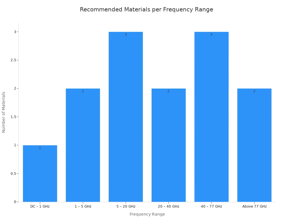
The frequency you use quickly limits your choices. Standard FR-4 works from DC to 1 GHz, where cost is the main factor. From 1 to 5 GHz, better FR-4 and the Rogers RO4000 series take over because steady dielectric constant becomes important. Between 5 and 20 GHz, dielectric loss matters most. RO4350B, RO3003, or Astra MT77 are the best picks. Above 20 GHz, both Dk tolerance and dissipation factor matter, so RO3003 and RT/duroid 5880 lead. Rogers RO4003C and RO4350B cover 500 MHz to 15 GHz with normal fabrication and a good balance of cost versus performance. Rogers RO3003 and RO3003G2 work for frequencies above 20 GHz, including 77 GHz car radar. RT/duroid 5880 fits satellites and phase-sensitive antenna arrays where lowest loss is more important than price.
Frequency Range | Recommended Materials | Primary Limiting Factor |
|---|---|---|
DC – 1 GHz | Standard FR-4 | Cost is the main driver |
1 – 5 GHz | Enhanced FR-4, Rogers RO4000 series | Dielectric constant (Dk) stability |
5 – 20 GHz | RO4350B, RO3003, Astra MT77 | Dielectric loss |
20 – 40 GHz | RO3003, RT/duroid 5880 | Dk tolerance and dissipation factor (Df) |
40 – 77 GHz | RO3003, RT/duroid 5880, Astra MT77 | All material properties become critical |
Above 77 GHz | PTFE-based materials, advanced thermosets | Requires specialised design |
A loss budget turns these ranges into a choice. At 12 GHz downlink, moderate rain adds about 0.28 to 0.38 dB per km, while extreme rain goes over 6.8 dB per km. Feeder loss from the transmission line adds to that total. A laminate with a low dissipation factor saves the remaining margin. For 5G base stations at 3.5 GHz or higher, Rogers materials are almost needed despite the higher cost, while cheaper FR-4 can serve less demanding parts to lower total system cost.
For printed circuit boards using frequencies above 10 GHz, newer generation substrates, Teflon, and flex substrates are the best choice because they are much better than regular FR-4 material.
Thermal and Cost Factors
Heat separates the suppliers. Rogers laminates have thermal conductivity up to 2 W/m-K, which moves heat away faster in high-heat designs. Taconic laminates range from 0.3 to 0.8 W/m-K and fit moderate heat, including car radar. When a car radar module makes a lot of heat, Rogers wins on heat management. When heat stays low, Taconic offers the cheaper path. Car radar also needs AEC-Q100 qualified materials rated for -40°C to +125°C, and aerospace programs need space-qualified materials with full tracking.
Cost ends the argument. Rogers high-frequency laminates cost $80 to $250 per square foot, while Taconic RF materials cost $60 to $150. Rogers costs five to ten times FR4. That price buys steady impedance, low loss, and heat room for high-reliability systems. Picking RF PCB material is never a single-factor choice. Frequency sets the floor, the loss budget sets the ceiling, and heat load decides if a mid-tier laminate works. Rogers PCB earns its price when signal integrity and heat removal both matter. Taconic covers cost-sensitive high-frequency designs. PTFE covers ultra-low loss. FR4 covers everything below 1 GHz. The right answer depends on which limit comes first.
Four things decide the choice: frequency range, loss budget, heat load, and cost. FR4 works for designs below 1 GHz. Rogers PCB materials fit high-performance RF systems that need steady impedance and low signal loss. PTFE handles ultra-low loss needs, while Taconic fits high-frequency work where cost matters. A material comparison always ends with the same question: which limit comes first?
Rogers PCB is worth its price when signal integrity and heat removal both matter. The laminates cost $80 to $250 per square foot, but they keep stable electrical properties across temperature and frequency. For radar, satellite, and precision RF designs, that stability is worth the money. No single high-frequency PCB material wins everywhere.
FAQ
When does a designer need Rogers PCB instead of FR4?
FR4 works well below 1 GHz. Above 6 GHz, you must use Rogers. Between 3 and 6 GHz, the loss budget tells you which to choose. Rogers PCB materials keep a steady dielectric constant and low signal loss at higher frequencies. FR4 cannot match that performance.
How does PTFE compare to Rogers laminates for ultra-low loss?
PTFE has the lowest loss tangent values. Rogers RT/duroid 5880 reaches 0.0009 at 10 GHz, matching pure PTFE. But PTFE moves and changes shape when heated. Rogers materials add ceramic fillers to hold their shape. This makes them easier to work with.
What role does dissipation factor play in material selection?
The dissipation factor measures how much signal energy turns into heat. A low dissipation factor means less signal loss. This matters most above 1 GHz. Rogers RO3003 has a value of 0.0010 at 10 GHz. Standard FR4 reaches 0.015–0.020.
Can Taconic materials replace Rogers for cost-sensitive designs?
Taconic RF materials cost $60–$150 per square foot. Rogers laminates cost $80–$250 per square foot. Taconic is cheaper when the loss budget allows. But Rogers has more stable electrical properties across temperature. Rogers also gives more design support and application notes.
Which high-frequency PCB material suits automotive radar?
Car radar needs materials rated for -40°C to +125°C. Rogers RO3003 works above 20 GHz, including 77 GHz radar. Its Dk temperature coefficient is +13 ppm/°C. Taconic laminates handle moderate heat at lower cost. The choice depends on heat needs and budget.
See Also
Exploring High Frequency PCB Production And Design For RF Uses
A Guide To Rogers R4350B R4003 And R5880 In RF PCBs
Discovering The Top Materials For High Speed PCB Design
Combining Rogers Material With TG170 For Hybrid PCB Construction
Choosing PCB Materials For Communication Products And Devices
