PCB Stator Electrical Testing and Insulation Verification
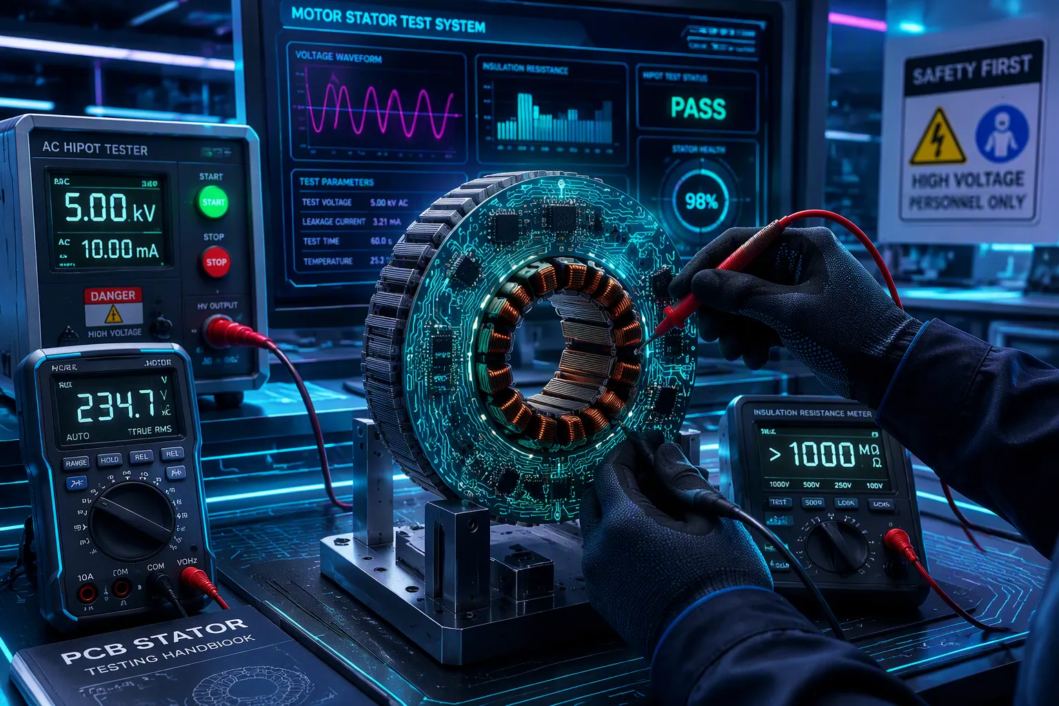
PCB stator electrical testing and insulation verification follow a set order: resistance, inductance, continuity, inter-turn short detection, hi-pot, insulation resistance, and partial discharge testing. Each step protects the next one. If you skip or reorder them, reliability suffers.
PCB stators fail in different ways than wire-wound stators. Copper traces, layer stacking, and thin dielectric films create unique fault modes. Standard motor test routines do not work the same way here. Technicians must adapt electrical testing to trace geometry and laminated structures. This article explains each test, the correct order, and why the sequence matters for production.
Key Takeaways
Do the tests in this order: resistance, inductance, continuity, inter-turn short, hipot, insulation resistance, and partial discharge. Each test gets the next one ready.
PCB stators break down in different ways than wound stators. They can have broken traces, shorts between layers, and thin dielectric breakdowns. Test at pads, vias, and connector pins.
Hipot and insulation resistance tests check the dielectric. They come after low-voltage checks. A board with a short should never reach these tests.
Keep the temperature, humidity, and cleanliness under control during testing. These things can change insulation resistance readings. Write down the conditions for each test.
Use pass/fail limits and trend data to find problems early. Track results over time to spot process drift. Fix common failures like inter-turn shorts and trace opens with process reviews.
PCB Stator Electrical Testing Needs
How PCB Stators Differ from Wound Stators
PCB stators use copper traces etched onto laminated boards instead of wound coils. This design change alters everything about fault modes and test access points. A traditional winding fails through turn-to-turn shorts or broken magnet wire. A PCB stator fails through trace opens, layer-to-layer shorts, or thin dielectric breakdown. Technicians cannot probe individual turns the way they would on a wound coil. They must instead test at pad locations, vias, and connector pins.
Stator testing is a production step that checks every electrical parameter before rotor insertion and final assembly. Finding a defect at this stage stops costly rework later. The insulation on laminations and traces greatly affects motor reliability. A weak dielectric film or a dirty surface can cause early failure in the field. Every test in the sequence exists to confirm that both conductors and insulation meet design intent.
Why Test Sequence Matters
The order of pcb stator electrical testing is not random. Each step protects the validity of the next one. Resistance and continuity checks come first because they confirm basic conductor integrity. If a trace is open, inductance and surge tests become meaningless. Inter-turn short detection follows, because a shorted turn can hide itself during simpler measurements.
Hi-pot and insulation resistance testing come after low-voltage checks. These tests apply elevated voltage to stress the dielectric. A board with a known short should never reach this stage. Partial discharge testing comes last, because it detects tiny defects that only appear under high stress. Skipping or reordering steps compromises reliability. A technician who jumps straight to hi-pot might destroy a board that a continuity check would have flagged. The sequence builds confidence layer by layer, from conductor to dielectric, before the stator moves to final assembly.
Electrical Testing of PCB Stators
Resistance and Continuity Checks
DC resistance measurement is the first step in pcb stator electrical testing. A technician hooks an ohmmeter to the phase leads and reads each path's resistance. For a star-connected stator with leads a, b, and c, the meter should show a low, even reading between any two leads. A reading between 0.2Ω and 2Ω is normal for BLDC motor phase windings, but the exact value depends on motor size and rating. An infinite reading means an open trace. A reading far below the expected value points to a short between turns or layers. The ohmmeter catches these faults before any high-voltage stress hits the board.
Continuity checks apply this same idea to every reachable pad and via. The technician makes sure current flows from connector pin to trace end without stopping. This step confirms the copper path is whole across all layers. A stator with a broken winding will fail here, well before inductance or surge testing starts.
Inductance, Surge, and Core Loss Tests
Inductance testing measures winding impedance and shows trace geometry errors. A trace that is too narrow, too long, or misrouted changes the inductance value. The tester compares each phase to the design specification. A mismatch points to a manufacturing defect that resistance checks alone cannot find.
Surge testing sends a fast voltage pulse to the winding and watches the decay waveform. Shorted turns in the winding create a distorted response. This method finds turn-to-turn faults that hide during low-voltage measurements. Core loss testing comes next, checking the lamination insulation condition. A damaged lamination coating lets eddy currents flow, which raises losses and heat. Together, these tests cover winding faults that simple continuity checks miss.
In-circuit testing (ICT) adds another layer of coverage for populated PCB stators. ICT uses a bed-of-nails fixture to probe individual components on a populated PCB. It checks resistor values, capacitor values, diode orientation, and IC presence without powering the whole assembly. This approach catches component placement errors from the SMT process. When paired with functional testing, ICT achieves comprehensive coverage.
In manual production environments, operators might spot-check units with a multimeter or run a sample through a bench-top test rig. That approach falls apart at volume. When you are running hundreds or thousands of units per shift, automated electrical testing is not a nice-to-have — it is the backbone of your quality system.
ICT offers clear advantages for medium to high-volume production:
ICT uses custom test fixtures, often called "bed of nails," to contact test points on a circuit assembly.
In-circuit testers perform tests faster than flying probe testers because they access multiple test points simultaneously.
The custom test fixtures required for ICT can be expensive, especially for low-volume production or prototypes.
Any changes in the PCB design may require updates to the test fixture, increasing test preparation time and cost.
These trade-offs matter when planning standard MCA tests and winding testing routines for production lines.
Hipot and Insulation Resistance Verification
Hipot and Insulation Resistance Tests
Once low-voltage checks prove the conductors are good, the focus moves to the dielectric. Random-wound stator coils and form-wound coils rated below 1 kV should have at least 5 megohms of insulation resistance. This number comes from ANSI/NETA ATS-2017 Table 100.11, which is based on IEEE Std 43-2013.
Winding Rated Voltage | Recommended Minimum Insulation Resistance in Megohms |
|---|---|
< 1,000 | 5 |
A technician runs a 500 volt insulation resistance test to measure leakage current across the insulation system. The meter sends a DC voltage and shows resistance in meg-ohms. Low insulation resistance readings mean moisture, contamination, or worn-out dielectric material. A reading below the minimum points to a possible ground fault risk.
High-potential (hipot) testing uses a raised AC or DC voltage to confirm dielectric strength. This test puts stress on the electrical insulation between conductors and ground. The board must handle the applied voltage without breaking down. Hipot and insulation resistance testing work as a team. One confirms the dielectric holds up under stress. The other measures how well it blocks leakage under normal conditions.
Partial Discharge and SIR Testing
Partial discharge testing finds localized dielectric defects that hipot testing may miss. Insulation breaks down in stages. Delamination and void formation open micro-voids between insulation layers, creating small air gaps. These air gaps are exactly where partial discharge activity starts. Because PD testing watches this discharge activity in real time, it can flag these localized defects at their source. An offline hipot test does not recreate the operating conditions under which these voids first become electrically active.
The two methods answer different questions and neither fully replaces the other. Offline testing gives a controlled, repeatable bulk-insulation baseline free of operational noise, which online PD monitoring cannot provide on its own. Online PD monitoring, in turn, catches discharge activity that only develops once the winding is under real thermal and mechanical load, which an offline test taken during a shutdown will never see.
Surface Insulation Resistance (SIR) testing checks PCB reliability under real-world environmental stress. For evaluating long-term insulation reliability of PCBs in humid environments, an SIR test is recommended under continuous power supply with high temperature and high humidity, specifically 85°C / 85% RH, combined with an applied bias voltage. During the test, the insulation resistance is watched continuously to detect metal migration paths that could lead to short-circuit hazards such as conductive anodic filament (CAF) growth.
Analyzers such as the Baker DX and Baker AWA-IV can do thorough motor insulation testing. These instruments combine hipot, insulation resistance measurements, and surge testing in one platform. They help technicians complete pcb stator electrical testing without switching between multiple tools. This consolidation cuts setup time and improves repeatability across production lots.
Test Fixtures and Environmental Control
Fixture Design and Contact Resistance
Probe fixtures decide how well a tester can reach the stator's test points. A bed-of-nails fixture pushes spring-loaded probes onto pads and vias. Bad contact adds extra resistance to every reading. This error hurts most during low-resistance measurements, where a few milliohms can turn a pass into a fail. Kelvin sensing fixes this problem. It uses separate force and sense leads at each probe tip. Current runs through the force pair, and the sense pair measures voltage right at the pad. Contact resistance drops out of the math. Technicians can then trust the reading for each winding and phase path.
Fixture maintenance keeps these measurements steady across production runs. Probes wear down, gather solder flux, and lose spring force over time. A worn probe tip raises contact resistance and causes false failures. Cleaning schedules and probe replacement intervals belong in the test procedure. Automated electrical testing systems depend on this discipline. A fixture that drifts weakens every later decision about the stator.
Temperature, Humidity, and Cleanliness
Temperature and humidity change how a dielectric acts. Warm conditions speed up molecular motion inside the insulation system and lower its resistance. Moisture on a board surface creates leakage paths that do not exist in dry air. A reading taken on a humid morning may look fine, while the same board fails on a dry afternoon. Technicians record ambient conditions with each result. That habit keeps insulation resistance data comparable between lots and shifts.
Surface cleanliness plays just as big a role. Flux residue, dust, and handling oils all carry small currents across a board. These contaminants lower insulation resistance and skew SIR results. The 85°C / 85% RH bias test exposes these weaknesses because heat and moisture speed up metal migration. A clean board passes. A contaminated one grows conductive anodic filaments and shorts. Controlled test rooms, gloves, and ionized air guns cut this risk. Every winding and every set of windings deserves the same clean, stable environment. Readings in meg-ohms only mean something when the test conditions stay fixed.
Understanding Results and Fixing Problems
Pass/Fail Limits and Trend Data
A technician first sets pass/fail limits using the design files. The CAD data shows the expected resistance, inductance, and capacitance for each phase. Then, past data from earlier production lots makes those limits tighter. If the first thousand units all read within a small range, the engineer makes the window smaller. This step catches drift before it turns into a defect. Electrical testing relies on these limits.
Trend data is just as important as any single reading. A stator that passes today may be close to the limit. Tracking values over time shows if the process is steady or slipping. For example, a slow rise in insulation resistance may mean the test room humidity changed. A slow drop in inductance may point to tooling wear. Teams that record every result find these patterns early.
Common Failure Modes and Fixes
Inter-turn shorts are one of the most common winding faults. These early winding shorts let current jump between turns that are next to each other. Shorted turns act the same way in a wound coil. The surge test finds them through a twisted decay waveform. A technician then checks the trace spacing and layer alignment. The fix includes reworking the etch process or throwing away the board.
Trace opens appear during continuity checks as infinite resistance. A broken copper path usually comes from a drill error or a handling scratch. The fix is a process review at the drilling station. Dielectric breakdown shows up during hipot or the insulation resistance test. A low reading means the insulation film has a weak spot. Early turn faults and winding faults between turns often share the same root cause: thin dielectric or dirty surfaces. Any winding fault needs a full review of lamination quality and cleanliness. The team should also check that every winding and all windings meet the minimum resistance value before release. A second check on the remaining windings confirms the fix. Each winding must pass before the stator moves forward. The windings then go to final assembly.
Every step in pcb stator electrical testing keeps the next one safe. Resistance and continuity checks prove the conductor is solid. Hipot and insulation resistance checks prove the dielectric is solid. You need both for a stator you can trust. A weak winding or damaged windings will break down out in the field. Teams should write down limits, fixture conditions, and environmental settings. This habit keeps results the same across production lots. When you add electrical testing to automated lines, stick to proven guidelines. High-accuracy fixtures keep contact steady. Data logging and MES integration give you traceability. These practices bring automated electrical testing into production without adding new failure risks. Every winding and all windings must pass before release.
FAQ
Can hipot testing happen before continuity checks?
No. The order keeps each test safe. Continuity checks come first to make sure no open or short exists. Hipot uses high voltage. A board with a hidden short could get damaged during hipot testing.
What is the lowest insulation resistance for a low-voltage stator?
For windings rated under 1 kV, the lowest insulation resistance is 5 megohms. This number comes from IEEE Std 43-2013 and ANSI/NETA ATS-2017 Table 100.11.
How is ICT different from flying probe testing?
ICT uses a custom bed-of-nails fixture that touches many points at the same time. It runs faster but costs more when fixtures need changes. Flying probe testing moves probes from point to point. It works well for prototypes and low volumes.
Why do technicians write down temperature and humidity during tests?
Temperature and humidity change insulation resistance readings. Warm air lowers resistance. Moisture creates paths for leakage. Writing down conditions keeps data similar between shifts and production lots.
What is the most common failure mode in PCB stators?
Inter-turn shorts and trace opens happen the most. Inter-turn shorts show up during surge testing as a twisted waveform. Trace opens show as infinite resistance during continuity checks. Both need a process review.
See Also
Investigating Thermal and Electrical Performance of Aluminum Printed Circuit Boards
Seven Essential Quality Control Steps for High Current Heavy Copper PCB Assembly in Cars
Evaluating Aluminum, FR4, and Flexible LED PCBs to Meet Your Requirements
Step by Step Process of Reverse Engineering Circuit Boards
Manufacturing Process for Aluminum-Based PCBs with Insulation Holes
