High TG PCB Quality Testing for Heat Resistance
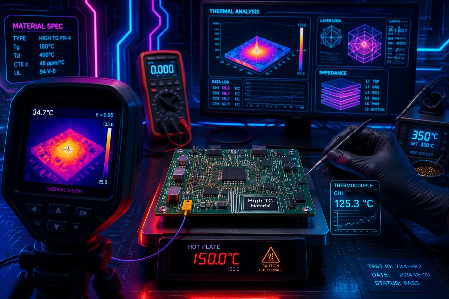
In demanding automotive and industrial electronics, a printed circuit board must handle heat stress to stay reliable. You cannot afford failures like layer separation or bending in the field. So, checking a High TG PCB's true heat resistance is a key engineering step. How can you confirm that a high tg pcb really stands up to thermal stress? Just picking high-tg materials is not enough. You need real proof through strict testing methods and standards. This article gives the key steps to check thermal resistance, read performance data, and make sure your high tg designs last. Proper testing tells apart strong high-tg pcbs from those that will break under heat—especially when the application demands exceptional durability for Heat Resistance.
Key Takeaways
High-TG PCBs use materials with a glass transition temperature (Tg) of 170°C or higher, so they stay stiff even in very hot conditions.
To check heat resistance, use tests like DSC, TMA, TGA, solder float, and thermal cycling, and follow IPC and UL standards.
Your PCB's Tg must be at least 20–25°C above its highest working temperature to keep it from softening and make sure it stays reliable over time.
TMA often gives more reliable Tg readings than DSC for high-TG materials, so using both tests gives you full confidence.
A high Tg by itself doesn't ensure the board will last. You also need to check Td, CTE, and other traits to make sure it can handle real heat and stress.
High TG PCBs and Testing for Heat Resistance
What Are High-Tg Materials?
A High TG PCB uses a laminate that stays stiff at high temperatures. The glass transition temperature is when the board changes from hard and glassy to soft and rubbery. For a high tg rating, this temperature must be 170°C or higher. Standard FR-4 usually has a Tg between 130°C and 150°C, while medium-grade materials are near 150°C. High-tg materials, however, often range from 180°C to 225°C.
PCB Type | Temperature Resistance (Tg) |
|---|---|
Standard copper-clad laminate | 130°C – 140°C |
Middle Tg | Greater than 150°C |
High Tg | Greater than 170°C (typical 180°C – 225°C) |
You need high-tg materials when your assembly runs near 125°C with a 30°C tolerance. In that case, the required tg value must be at least 155°C, which makes the 170°C threshold the best choice. Different resin systems give different performance. High-Tg FR-4 has a tg range of 150°C to 180°C. Polyimide can handle temperatures up to 260°C. BT epoxy resin usually gives a tg between 200°C and 250°C. Each material affects pcb performance differently, so you must pick the laminate that matches your thermal needs.
Thermal Stress Scenarios for High-Tg PCBs
Heat resistance testing is important because real-world conditions push boards to their limits. Standard PCBs can soften, warp, or melt at very high temperatures, which makes their electrical properties fail. High-tg pcbs have a resin system that can handle lead-free soldering and gives more mechanical strength in tough conditions. Without proper testing, you risk delamination and warping in the field.
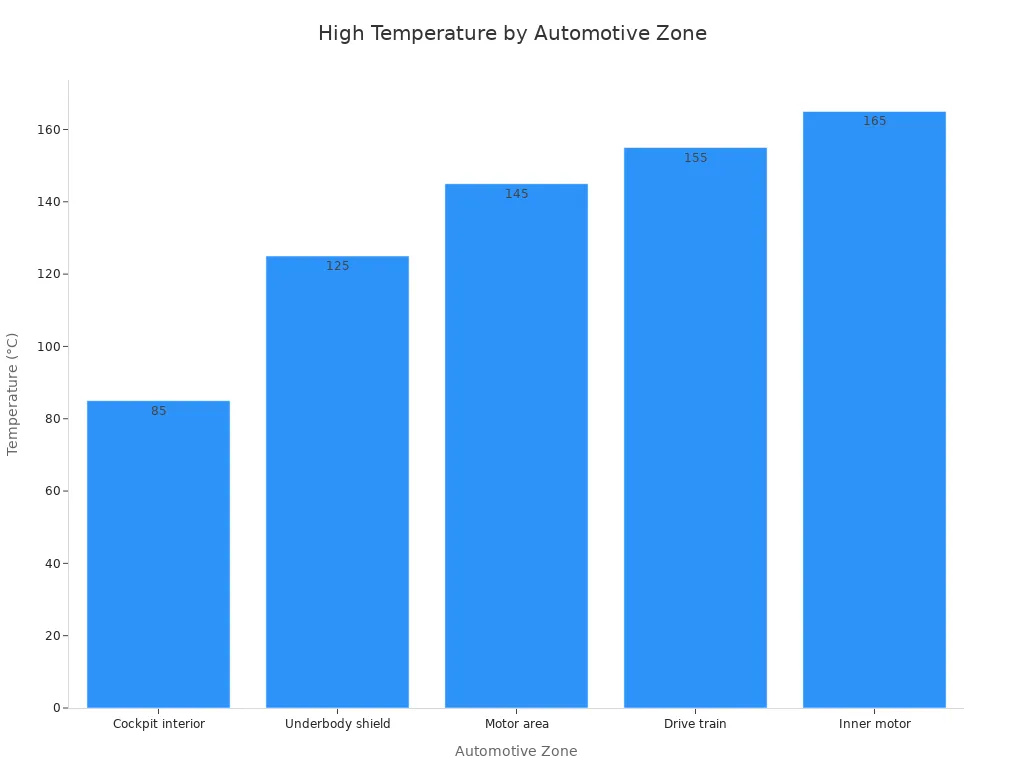
Automotive uses show the range of heat stress. The cockpit interior has temperatures from -40°C to 85°C. The underbody shield reaches 125°C. Motor areas go up to 145°C, and the drive train hits 155°C. Inner motor zones can get to 165°C.
Industrial environments have similar challenges. General surrounding temperatures range from -40°C to 85°C, but high-power electronics and motor drives often go above 125°C. Quick temperature changes create thermal cycling and shock, which test the board's strength. These situations need careful testing to make sure your high tg pcb keeps its electrical performance and mechanical stability. The glass transition temperature must be 20–25°C higher than your maximum working temperature to stop thermal damage. This gap protects against softening and ensures long-term reliability. Testing for heat resistance is not optional; it directly affects your product's durability and prevents expensive field failures.
Key Test Methods for High-Tg PCBs
To check your board's heat resistance, you run specific tests. Each test looks at a different part of heat resistance. The main tests are DSC, TMA, TGA, solder float, and cycling. IPC-4101 and IPC-6012 set the pass/fail rules. Your material's tg must be at least 20–25°C above your highest working temperature.
Tg Measurement via DSC and TMA
Two methods give the most reliable tg measurement for high-tg materials: DSC and TMA. DSC measures heat flow compared to a neutral reference. It finds the change in heat capacity at the glass transition temperature. This method gives start, middle, and end temperatures. Faster heating rates make it more sensitive but shift the tg value. Modulated DSC separates reversing and non-reversing changes. You get a reliable tg even when cure reactions overlap.
TMA measures size changes as the sample heats. The tg shows up as a change in the expansion slope. For filled, highly crystalline, or crosslinked materials common in high-tg pcbs, TMA works better than DSC. The size changes at tg are large. IPC-4101 says to use TMA for thermal analysis to find tg for high tg materials. These materials usually give a tg above 180°C. For a high tg pcb, TMA often gives better results than DSC. You pick the method based on your material type, especially for high-tg materials. For thermosetting resins in pcbs, DSC works well. For filled laminates, TMA gives clearer results. Using both methods together gives the most complete picture of thermal behavior. The best tg value for your use depends on your working temperature range. Your chosen material must have a tg at least 20–25°C above your highest working temperature. These materials are called high tg laminates. This safety margin protects against softening during assembly and field use.
Td, Solder Float, and Thermal Cycling Tests
Beyond tg, you check the decomposition temperature. You run IPC-TM-650 2.4.24.6 to find the exact temperature where a sample loses 5% of its weight. This 5% weight loss point shows that the resin is starting to break down during high heat tasks like lead-free soldering. For standard FR-4, the Td range is 310–320°C. For high tg FR-4, the Td goes up to ≥340°C. Most solder temperatures during assembly are between 200°C and 250°C, so your Td must be higher than that. Td is a hard limit for pcb materials. When a material reaches its Td, the changes in its properties are permanent. Unlike tg, where properties return when cooled, Td damage stays.
The solder float test mimics wave soldering shock. You float the sample in solder at 288°C for 10 seconds. You repeat this 3 to 6 times. The pass/fail rules require no blistering, delamination, or measles on the board. This test directly checks your board's ability to survive assembly without damage.
Cycling tests check long-term reliability. You cycle the board between -40°C and +125°C in a controlled chamber. Some standards require a range of -55°C to 150°C. Each cycle has dwell times up to 30 minutes. The total cycle count often goes over 1000. This high-temperature exposure creates cyclic stress, especially near low tg resin borders. The test checks the board's resistance to fatigue. You should also measure peel strength under hot loads to make sure circuit trace bonds stay strong. The Z-axis CTE from 50°C to 260°C must stay below 3.5% to reduce stress at copper-laminate interfaces. The Interconnect Stress Test cycles vias through temperature extremes. A resistance change below 10% after 500 cycles means a pass. These tests together confirm that your high-tg materials deliver the performance you expect. The best tg value ensures the board's performance under heat. Quality control relies on consistent testing of these procedures. Electrical integrity depends on the material surviving these demands without breaking down.
Interpreting Heat Resistance Data and Standards
Reading test curves correctly matters just as much as running the tests. You need to know what a pass looks like on a DSC or TMA graph before trusting your high tg pcb. Let's walk through the interpretation process step by step.
IPC and UL Standards for High-Tg PCBs
IPC-4101 sets the baseline for laminate materials. This standard defines the key requirements your high-tg materials must meet. You should check several properties when reviewing a datasheet. The glass transition temperature tells you where the resin softens. Low coefficient of thermal expansion minimizes dimensional changes that stress plated holes. Low moisture absorption prevents delamination and electrical degradation. Dielectric constant and dissipation factor control signal speed and loss. Peel strength measures how well copper clings to the laminate. Thermal stress testing verifies integrity under short solder exposure. Volume and surface resistivity check electrical resistance under humid conditions. Dielectric breakdown tests the insulator's ability to handle high voltage. Flexural strength applies to thicker laminates. Arc resistance measures how long an insulating surface resists becoming conductive under high voltage.
Key Requirement | Description / Purpose |
|---|---|
Glass Transition Temperature (Tg) | Temperature range where resin transitions from rigid to pliable; critical for RoHS compliance and thermal performance |
Low Coefficient of Thermal Expansion (CTE) | Minimizes dimensional changes with temperature, reducing stress on plated holes and traces |
Low Moisture Absorption | Reduces rate of water uptake in epoxy composite, preventing delamination and electrical degradation |
Dielectric Constant (Dk) & Dissipation Factor (Df) | Electrical properties controlling signal speed and loss; Df measures electromagnetic field absorption |
Peel Strength | Bond strength of metal cladding under various conditions |
Thermal Stress | Determines thermal integrity under short-term solder exposure |
Volume & Surface Resistivity | Measures electrical resistance under humid conditions |
Dielectric Breakdown | Insulator's ability to withstand high voltage stress |
Flexural Strength | Mechanical strength under applied load for laminates ≥0.51mm thickness |
Arc Resistance | Time for insulating surface to become conductive under high voltage/low current arc |
UL 746E covers end-product safety for polymeric materials on printed wiring boards. The Relative Thermal Index (RTI) is the primary heat resistance metric. It shows the maximum temperature your pcb base material can handle for extended periods without losing properties. The Comparative Tracking Index (CTI) measures resistance to surface tracking under electrical stress and moisture. This metric prevents short circuits and fires. UL 746E also includes dielectric tests after environmental exposure, ignition resistance, and surface tracking evaluations. These checks mitigate fire risks in consumer and industrial electronics.
Common Pitfalls in Test Data Interpretation
Engineers often misread Tg onset points. TMA detects Tg as the intersection of two linear CTE slopes. You see a step change in expansion rate. For highly crosslinked thermosets common in high-tg pcbs, the DSC heat-flow signal at Tg appears weak. TMA gives more sensitive and reliable results. This explains why you should rely on TMA curves when DSC results look ambiguous.
Key interpretive insight: TMA detects Tg as the intersection of two linear CTE slopes. For highly crosslinked thermosets and composites common in High TG PCBs, the DSC heat-flow signal at Tg is often weak, making TMA more sensitive and reliable for confirming heat resistance compliance.
You also need to apply the correct margin. Engineers require the measured tg to be 20–30°C higher than the maximum operating temperature. For a device running at 125°C, your pcb must have a tg of at least 155–160°C. This margin ensures adequate heat resistance during assembly and field use.
DSC shows a step in heat capacity at Tg
TMA shows a slope change in dimensional expansion
Both methods identify the tg value that must meet the margin requirement
Another common mistake involves ignoring CTE consistency. A single Tg reading does not tell the whole story. Your Z-axis expansion must stay controlled across the entire temperature range. High CTE values create stress at copper-laminate interfaces, leading to via failures. Check that your material maintains consistent expansion behavior, not just a high Tg number.
Quality testing for heat resistance requires you to look at the complete picture. A high tg value alone does not guarantee reliability. You must verify thermal performance across multiple parameters. The electrical performance of your board depends on material integrity under stress. When you interpret data correctly, you catch problems before they reach the field. This careful review separates reliable high-tg materials from those that fail under real conditions.
Best Practices for High-Tg PCB Heat Resistance
Integrating Testing into Manufacturing Workflow
You must add heat resistance testing to every step of production. Start by checking high-tg materials when they arrive. The tg of the laminate controls its heat resistance. IPC standards give the rules for this process.
Standard | Role in Heat Resistance Testing |
|---|---|
IPC-A-600 | Sets visual pass/fail rules for board appearance, including pits or scratches that could affect thermal performance. |
IPC-6012 | Defines electrical, thermal, and mechanical performance needs for the finished board. |
IPC-A-610 | Covers assembly quality, including soldering and cleanliness, which affects heat resistance. |
IPC-2221 | Provides design rules for layout and material choice to support thermal resilience. |
Use these six testing steps for high-tg materials during manufacturing:
Pre-bake and moisture removal: Heat boards at set temperatures before adding parts to remove water, prevent bubbles, and stop layer separation during soldering.
Thermal shock testing: Quickly change board temperature to find via cracking or delamination caused by uneven material expansion.
Burn-in testing: Run the board under high heat and electricity for long periods to reveal hidden defects.
CTE testing: Measure how much the board grows with heat to prevent cracks in plated through holes.
Thermal cycling: Heat and cool the board repeatedly to expose weak spots, making sure the tg value fits the application.
Controlled cooling: Cool boards slowly after hot steps. Use high tg materials with tg 20–30°C above the hottest use case.
Material Selection for High-Tg PCBs
Pick materials with proven heat performance and proper certifications. Look for ISO 9001:2015, UL certification, and IPC-6012 Class 3 compliance. IATF 16949 applies for automotive projects. RoHS compliance ensures environmental safety.
When selecting high tg pcb materials, make sure the glass transition temperature is at least 20°C higher than the device's maximum operating temperature. This margin stops the laminate from softening during operation, keeping mechanical integrity and preventing warping or delamination.
Apply the operating temperature margin rule carefully. Your material's tg must sit 20–25°C above your highest working temperature. A proper tg rating keeps the board rigid. High tg laminates come with UL certification for safety. The thermal conductivity of your laminate affects heat dissipation. High-tg materials often pair with good thermal conductivity to boost pcb performance. The material's tg value directly affects long-term reliability.
Follow these design practices:
Use copper planes and vias to move heat away from critical components.
Increase board thickness to improve rigidity and reduce warping under stress.
Adjust trace widths to match the material's expansion characteristics.
Work closely with the fabricator to optimize the design for the specific high tg material.
These steps ensure that your high-tg pcbs deliver reliable operation. Quality control at every stage prevents field failures.
Verifying heat resistance requires a combination of tests. You need tg measurement, Td analysis, thermal cycling, and solder float tests. These tests must align with IPC and UL standards. The tg value of your high-tg materials determines their performance.
High-tg pcbs are only as reliable as the tg testing you perform.
Validate your high-tg materials early in the design stage. This step prevents field failures. High-tg materials must prove their durability for heat resistance. A high tg pcb depends on proper tg selection. The right tg value ensures mechanical stability. Thermal reliability continues to grow in importance. High tg rating protects your design. High tg performance requires consistent testing. High tg materials need correct tg. The best value prevents failure.
FAQ
How often should I test high-tg materials during production?
Test high-tg materials when they arrive and again after fabrication. Pull a sample from each batch for thermal cycling. This catches material variations early. Consistent testing prevents field failures. Your quality plan should include these checks at every stage.
What is the minimum tg value for automotive applications?
Your tg must sit 20–25°C above your maximum operating temperature. For underbody electronics at 125°C, you need a tg of at least 150°C. High tg laminates rated at 170°C or higher provide the safest margin for demanding zones.
Can I rely on DSC alone for tg measurement?
DSC works well for many materials, but TMA often gives clearer results for high-tg materials. Highly crosslinked thermosets show weak DSC signals at tg. TMA detects the slope change in expansion more reliably. Use both methods when you need complete confidence.
What does a failed solder float test tell me?
A failed solder float test shows your pcb cannot survive assembly heat. Blistering or delamination after 288°C exposure means the laminate lacks proper heat resistance. You should reject that batch and investigate the material's quality. This test protects your production line from defective boards.
How does CTE affect high tg pcb reliability?
Z-axis CTE controls stress at copper-laminate interfaces. High expansion causes via cracking and delamination during thermal cycling. Your material must keep Z-axis expansion below 3.5% from 50°C to 260°C. A high tg value alone does not guarantee dimensional stability.
See Also
High Tg FR4 Boards Excel in Extreme Thermal Environments
Ceramic Circuit Boards Offer Superior Thermal Management
Manufacturing Techniques for Heavy Copper Multilayer Boards
Seven Key QC Measures for Automotive Heavy Copper PCB Assembly
