The Complete Guide to High TG PCB Prototyping and Small Batches
Your prototype stops working after many hours. The board bends, traces lift, and solder joints break. Heat caused this damage. You need a high tg pcb.
High TG PCBs handle heat better than normal boards. Their glass transition temperature is 170°C or higher. This means they keep their shape under heat stress. You need this material when your design works near heat sources or goes through lead-free soldering.
This guide explains material differences, manufacturing challenges, and money-saving tips for your high-tg pcb prototype. You'll learn when to choose high-tg pcb materials and how to handle small batch production without losing quality. Your next high-tg pcb prototype will survive the heat.
Key Takeaways
High TG PCBs handle heat better than regular boards. They stay in shape during soldering and use.
These boards stay stable under heat cycles, preventing cracks in vias and keeping layers from separating.
Choose materials with Tg above 170°C for car or high-power designs. Picking the right materials cuts your prototype cost.
Work with a certified manufacturer for fast prototypes. Pick standard materials and simple designs to get parts quicker.
What is High Tg PCB? Definition and Importance
Tg stands for glass transition temperature. This is the point where a PCB material changes from a hard, glass-like state to a softer, rubbery one. Below Tg, the material stays stiff and stable. Above Tg, it starts to expand, bend, and lose strength. For a high tg pcb, this point is much higher than for standard materials. So the board keeps its shape and strength even in strong heat.
What is Tg and How is it Measured?
You can measure Tg with three main methods. Each one looks at a different physical response. The table below shows these methods and their IPC standards.
Method | Physical Response Measured | IPC Standard |
|---|---|---|
DSC | Heat flow change across transition | IPC-TM-650 2.4.25 |
TMA | Dimensional expansion change | IPC-TM-650 2.4.24 |
DMA | Mechanical modulus and damping under oscillating load | IPC-TM-650 2.4.24.2 |
DMA, or Dynamic Mechanical Analysis, uses an oscillating mechanical force on the material. It finds Tg by a big drop in storage modulus. This makes it very sensitive for PCB substrates. TMA, or Thermomechanical Analysis, measures size changes as the material softens under a small constant load. This method gives useful data on the coefficient of thermal expansion. Since these methods watch different physical responses, valid tests can give different Tg values for the same resin. IPC says to report the method along with the Tg value.
High TG vs Standard PCBs: Key Differences
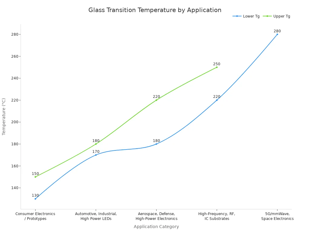
Standard FR-4 materials have a Tg range of 130-140°C. High tg materials start at 150°C, with most high-tg pcb products in the 170-180°C range. Materials above 170°C count as "Very High-Tg" and serve automotive and aerospace industries. The table below compares common material categories.
Application Category | Tg Range (°C) | Material Type |
|---|---|---|
Consumer Electronics / Prototypes | 130–150 | Standard FR4 |
Automotive, Industrial, High Power LEDs | 170–180 | Enhanced FR4 (High-Tg) |
Aerospace, Defense, High-Power Electronics | 180–220 | Polyimide-based |
High-Frequency, RF, IC Substrates | 220–250 | PTFE (Teflon), Ceramic |
5G/mmWave, Space Electronics | >280 | Rogers Laminates |
The difference matters most during lead-free soldering. Lead-free soldering usually needs higher processing temperatures. These can stress materials with low Tg values. High tg materials handle these higher temperatures well. This keeps the PCB strong and meets modern manufacturing standards.
High Tg PCBs use advanced materials with a Tg of 170°C or higher, sometimes reaching 200°C or more, allowing them to withstand extreme temperatures without warping or delamination during soldering or prolonged operation.
The coefficient of thermal expansion (CTE) also differs a lot. High Tg FR-4 has a CTE along the z-axis of 50-60 ppm/°C. Standard FR-4 sits at 70 ppm/°C. When standard FR-4 goes just 10°C above its Tg, its CTE jumps by 300%. This risks via failures. A high-tg pcb stays dimensionally stable because its lower CTE reduces expansion stress on plated through-holes and copper traces.
You need a high-tg pcb when your design works near heat sources, goes through lead-free assembly, or faces repeated thermal cycling. High tg materials resist CAF formation, keep bond integrity, and stop delamination. For prototypes meant for automotive engine control units, aerospace avionics, or high-power LED lighting, picking high tg materials from the start prevents costly redesigns later.
Advantages of High-Tg PCB for Thermal Performance
When you pick a high tg pcb, you get three big benefits: it keeps its shape, resists CAF damage, and lasts longer under heat stress. Normal PCBs get weak when temperatures rise. A high tg pcb stays strong. That is why it works best for tough jobs.
Thermal Performance Circuit Boards: Stability and Reliability
A high tg pcb keeps its shape during heating and cooling cycles. Below Tg, the material grows at a slow, steady rate. Above Tg, the Z-axis CTE can jump by three times or more. High Tg materials hold the resin steady until a higher heat point. This stops too much Z-axis growth that would pull copper barrels and cause tiny cracks. Your vias and plated through-holes stay safe.
The table below shows how a high-tg pcb stays stable.
Mechanism | Impact on Dimensional Stability |
|---|---|
Below Tg, FR4 grows at a slow, steady rate; above Tg, Z-axis CTE can jump by 3x or more | Higher Tg keeps the material in a steady low-growth range across a wider heat window |
Z-axis growth pulls copper barrels in plated through-holes and vias | Less Z-axis growth stress on plated through-holes and vias stops barrel cracks and keeps holes strong |
Steady low-growth range during heating and cooling cycles | Better shape stability for fine line and high-density designs; lower risk of layer separation and white spots; improved layer alignment |
Better shape stability means less bending after reflow or baking. This matters for small, tight parts. Your boards handle many heat cycles without tiny cracks. This makes them last longer in car ECUs and factory controls. A stronger material above Tg stops barrel cracks in vias under heat and pressure.
CAF resistance is another key plus of a high tg pcb. Using a high-tg pcb cuts down small resin cracks under strong electric loads, helping stop CAF formation. High Tg FR4 laminates keep electrical performance and reliability, lowering the risk of CAF-related failures. Materials like Isola 370HR show strong CAF resistance as a key plus. A high-tg pcb ensures long-term reliability in wet and high-voltage conditions.
Industry Applications: Automotive, Aerospace, and More
Car environments need thermal stability circuit boards. Engine control modules face heat over 125°C. The table below shows what car PCBs need.
Parameter | Requirement |
|---|---|
Continuous operating temperature range | -40°C to +150°C |
Maximum ambient temperature | 125°C |
Localized hot spot temperature | >150°C |
Minimum glass transition temperature (Tg) | 170°C (180°C+ for highest-temp applications) |
Minimum decomposition temperature (Td, 5% weight loss) | 340°C |
Z-axis CTE (through Tg) | <50 ppm/°C |
A high tg pcb meets these needs. Standard FR-4 with Tg at 170°C works for easier car jobs. Polyimide substrates rated up to 260°C work in engine control units and powertrain systems. Temperature swings from -40°C to 125°C, constant shaking, and wet conditions make a high-tg pcb vital for reliable electronics.
Aerospace jobs need advanced heat handling. Avionics systems face quick temperature changes and high heat. A high temperature pcb with polyimide materials handles these conditions. Factory gear like motor drives and power supplies makes heat while running. High-performance PCBs with high Tg materials keep these systems working reliably.
LED lighting also gains from a high tg pcb. High-power LEDs make a lot of heat. The board must spread this heat without breaking down. A high tg pcb keeps its properties over time. This ensures a long life for your LED products.
You need a high-tg pcb for designs near heat sources, lead-free assembly, or repeated heating and cooling cycles. These thermal performance circuit boards are vital for high-temperature circuit designs in cars, planes, factories, and lighting.
Design and Manufacturing Considerations for High-Tg PCB
Material Selection for High-Tg PCBs
You pick materials based on thermal stability, CAF resistance, dimensional stability, and lead-free compatibility. Your high tg pcb needs a Tg above 170°C for automotive use. A device running at 125°C requires a minimum Tg of 170°C. Choose high tg materials that meet these thresholds. A high tg pcb starts with the right laminate. The table below shows a common high tg material.
Property | Value |
|---|---|
Standard FR-4 Tg | 130-140°C |
High Tg FR-4 Tg | 170-180°C |
High Tg FR-4 Z-axis CTE | 50-60 ppm/°C |
Max soldering temperature (no delamination) | 260°C |
Thermal conductivity matters for heat dissipation. Standard FR-4 has lower thermal conductivity than high Tg materials, which often use advanced composites for better heat dissipation. You also need low CTE. For example, high Tg FR-4 materials have a CTE of 50-60 ppm/°C, compared to 70 ppm/°C for standard FR-4. These high tg materials improve board reliability. Polyimide materials have a Tg in the range of 180-220°C and are known for high thermal stability.
For high-speed circuits, pick low-loss laminates. For high-temperature boards, choose polyimide or high-tg materials. These high tg materials drive reliability in harsh environments. A high tg pcb survives thermal cycling better.
Fabrication Challenges and QA
High tg materials are harder than standard FR-4. This creates manufacturing challenges. You need slower drill speeds and harder bits. Lamination needs higher temperatures. A high-tg pcb needs careful manufacturing to avoid defects.
Your layer stackup must be symmetric. Core and prepreg should match in Tg and resin content. Place power and ground planes next to signal layers. This helps heat dissipation and capacitance coupling. For vias, keep aspect ratios below 10:1. Use staggered patterns in dense areas. Backdrilling removes stubs in high-speed nets. These design rules improve your high tg pcb performance.
Quality assurance follows IPC standards. IPC-4101 defines laminate requirements for high Tg substrates, including minimum Tg and Td values. IPC-6012 sets bow and twist limits for Class 3 boards. IPC-TM-650 provides test methods. Method 2.4.25 (DSC) checks resin cure and Tg. Method 2.4.24 (TMA) measures Z-axis expansion and CTE. The solder float test is used to verify bonding at high temperatures.
Perform controlled bake-out before lamination. Verify incoming material Tg through DSC testing. These steps ensure your high tg pcb meets reliability standards. Every high-tg pcb needs this care. Good pcb manufacturing starts with material selection and ends with thorough testing. Your high-performance pcbs need this attention to detail. A high-tg pcb design requires careful planning.
High-Tg PCB Prototyping: Cost and Turnaround
You need your high-tg pcb prototype fast. Standard high-tg pcb quick turn services offer rapid delivery, enabling fast design validation. This speed lets you test designs without long waits. Rapid prototyping keeps your project moving while you validate thermal performance.
Cost Drivers for High-Tg PCB
Material choice drives most of your high-tg pcb prototype cost. High tg materials cost more than standard FR-4. The laminate itself represents the largest single expense. Layer count also matters. A 12-layer board costs far more than a 6-layer design. Each layer adds material, processing time, and inspection steps.
Production volume changes your per-unit price dramatically. When you order 1,000 units, each board carries a certain cost. Increase that order to 10,000 units, and the per-unit price drops significantly due to economies of scale. Your high-tg pcb prototype cost per unit falls as quantity rises.
Turnaround time adds another cost layer. Expedited services carry a premium over standard lead times. You pay extra for the convenience of faster delivery. The table below shows how different factors affect your budget.
Cost Factor | Cost-Saving Strategy | Impact on Quality |
|---|---|---|
Material Type | Choose standard FR-4 over exotic high-Tg laminates unless thermal demands require it | Maintains reliability for most applications |
Layer Count | Reduce from 12-layer to 6-layer designs where possible | Lower complexity still meets functional specs |
Quantity | Order small batches to minimize prototype cost | No quality change; same manufacturing process |
Turnaround Time | Avoid expedited services unless strictly necessary | Standard lead time preserves quality control |
Balancing Quality and Budget
You can manage high-tg pcb prototyping costs without sacrificing reliability. Start by checking your actual thermal requirements. Many designs work fine with standard FR-4. Only choose high tg materials when your application truly needs them. Verify dielectric constants, thicknesses, and copper weights against your actual needs. This prevents unnecessary material cost inflation.
Strategy: Avoid over-specification by selecting standard FR-4 laminates unless thermal or frequency demands truly require high-Tg materials. Verify dielectric constants, thicknesses, and copper weights against actual application needs. This prevents unnecessary material cost inflation while maintaining reliability for most designs.
For small batch production, optimize panel utilization. Combine multiple designs on one panel to reduce waste. Work with manufacturers who offer flexible ordering options. A good partner helps you balance your high-tg pcb prototype cost against delivery speed. Your prototype phase should validate the design, not drain your budget. Smart planning keeps your high-tg pcb prototyping efficient and affordable.
Choosing a High-Tg PCB Prototype Manufacturer
Selecting the Right Manufacturer
Your high-tg pcb prototype needs a partner with strong credentials. Start by looking for certifications such as ISO 9001 for quality management and AS9100 for aerospace. These certifications prove the manufacturer follows strict documentation and control processes.
Experience with high-tg materials sets capable vendors apart from generalists. Ask about their history with rigid, flex, and rigid-flex boards. A manufacturer with decades in heat-resistant fabrication understands the unique challenges of high-tg pcb quick turn services. They know how to handle hard materials during drilling and set proper lamination temperatures.
Check their testing capabilities. Thermal stress testing, electrical testing, and X-ray inspection confirm reliability under high-temperature conditions. Industry standards guide their assembly work. Ask for material certificates for every batch. These documents confirm the laminate meets specified Tg values and other key properties.
Prototyping Best Practices
Start your high-tg pcb prototype project with a complete data package. Gerbers, stack-up details, and impedance targets must be ready before the lead time clock starts. Incomplete data delays your high-tg pcb prototype services. Standard materials like high-temperature FR4 move fastest through production. Specialty laminates extend lead times by a lot.
Create a dual-source approved vendor list. Validate equivalent materials with matched dielectric constant and dissipation factor values. Define acceptable tolerance bands for these properties on your drawings. This approach lets your manufacturer substitute materials within a controlled performance range without redesigning your board.
Coordinate with your fabricator on material availability. Some high-tg grades require extended bookings. Place your purchase order early so the manufacturer can secure materials while you finalize your design. Simpler builds with 1-8 layers process faster than complex HDI designs with blind and buried vias. Your via strategy directly affects your high-tg pcb quick turn timeline.
Work with a manufacturer that offers prototype-to-production support. This continuity ensures your high-tg pcb prototype transitions smoothly into small batch manufacturing. Responsive engineering teams answer questions before they become problems. Your high-tg pcb prototype services should include clear communication about every step. A reliable partner makes your pcb prototyping efficient and your production predictable.
High TG PCBs deliver the thermal stability your designs demand. You now understand when to choose them and how to manage costs. Your high-tg pcb prototype validates performance before full production. Small batches remain affordable with smart panel utilization and standard materials.
Material selection drives your prototype success. Vetting manufacturers ensures quality through certifications and testing. These steps protect your reliability goals.
Evaluate your current projects for heat exposure. If your design faces lead-free soldering or high operating temperatures, request a quote from a trusted manufacturer. Your next high-tg pcb prototype will survive the heat and deliver reliable electronics for years.
FAQ
What Tg value does my high-tg pcb prototype need?
Your design needs a Tg above 170°C for cars or high-heat jobs. Standard FR-4 with Tg around 130-140°C cannot handle lead-free soldering or many heat cycles.
Can I use standard FR-4 instead of high Tg materials?
You can use standard FR-4 for designs with low heat. Pick high Tg materials when your board sees temperatures above 125°C or lead-free assembly. Check your working area first.
How does high Tg affect my prototype cost?
High Tg laminates cost more than standard FR-4. The material choice is the biggest cost. You can cut your prototype cost by ordering small batches and using panels well.
What certifications prove a manufacturer's quality?
Look for certifications such as ISO 9001 for quality management and AS9100 for aerospace. These certifications show the maker follows strict rules and records.
How fast can I get boards for testing?
Standard high-tg pcb quick turn services offer fast turnaround, with expedited options available at a premium. Plan your project timeline to match.
See Also
Expert Guide To Heavy Copper Multilayer PCB Production
Key Steps For Rapid Turnkey PCB Assembly Process
Complete Guide To Flexible PCB Manufacturing Methods
