PCB Stator Layout: Manufacturing Considerations
A PCB stator motor works best only when engineers design it so it can be built. Electrical math alone cannot promise a product that works. Which layout choices decide if a stator design makes it to production in a reliable and low-cost way? Trace widths, layer counts, via placement, and material choices all play key roles. A custom PCB motor built on a thin disc design needs close attention to copper thickness and heat paths. Good pcb stator layout also means balancing axial flux geometry with the limits of making it. Designers of pcb stators must follow standard drill sizes, annular rings, and solder mask clearances. Working with fabricators early stops costly redesigns. A pcb stator design that ignores assembly limits will fail, no matter how clean the schematic is. Smart pcb stator technology choices, from substrate selection to via arrays, separate prototypes that grow from those that get stuck. Every pcb stator layout choice has results for production.
Key Takeaways
Talk with your fabricator while you design the layout. This helps you catch rule violations early and avoid costly re-spins.
Pick the right base material, such as FR-4 or polyimide, and the right copper weight. Base your choice on how much heat and current the board must handle.
Keep copper balanced on all layers to avoid bending and protect the motor's air gaps.
Place groups of thermal vias under the windings and copper pour. This helps pull heat away from hot spots quickly.
Follow IPC Class 3 annular ring rules for high-reliability stators, and Class 2 for consumer designs.
DFM Principles for PCB Stators
Design for manufacturability helps turn a smart motor design into a product that factories can really build. PCB stator design flexibility lets engineers change dimensions and winding patterns easily. If you change trace routing or coil geometry, you only need a new artwork file, not a rebuilt winding machine. This flexibility makes pcb stators easier to manufacture than traditional wound copper coils.
Automated production equipment does the heavy work. Pick-and-place machines, etchers, and laminators run fast with tight repeatability. According to Swimbi, this highly automated process lowers overall production costs while enabling high precision and accuracy. The same automation reduces defects and errors during manufacturing. A motor design to production flow that once needed manual coil winding now runs through standard pcb fabrication lines.
Standard Fabrication Constraints
Every fabricator publishes a set of manufacturing constraints that define what their process can achieve. These limits cover minimum trace width, spacing, drill diameter, and annular ring. A design-to-manufacture tool checks these rules automatically before release. DFM analysis finds possible production issues before tooling begins by checking that a PCB design meets manufacturing capabilities such as minimum trace widths, spacing, and hole sizes. DFA analysis further improves component placement and orientation for reliable assembly, considering solder joint quality, thermal management during reflow, and automated test accessibility. DFT adds test points and boundary scan features so that manufacturers can check component operation and interconnection before boards reach customers, catching defects early in production. Together these checks stop defects from being designed in, rather than finding them only after fabrication.
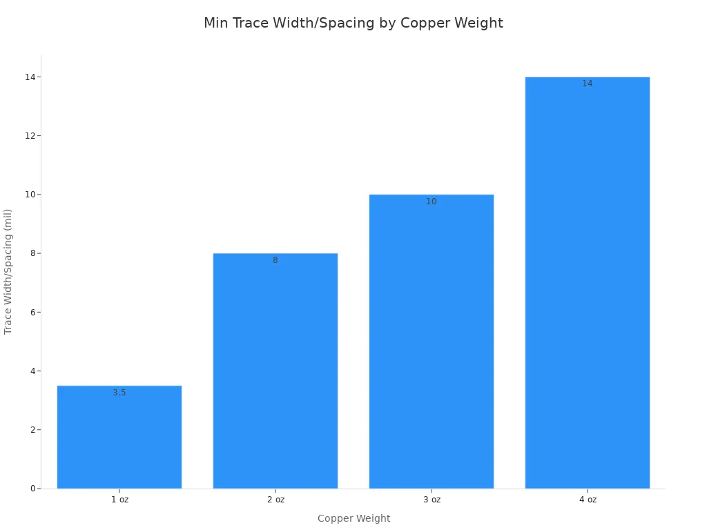
Copper weight drives the tightest constraints. Heavier copper needs wider traces and larger gaps because etching becomes less precise as thickness grows.
Copper Weight | Minimum Recommended Trace Width / Spacing |
|---|---|
1 oz | 3.5 mil (0.089 mm) |
2 oz | 8 mil (0.203 mm) |
3 oz | 10 mil (0.254 mm) |
4 oz | 14 mil (0.355 mm) |
These values serve as general minimum recommendations for PCB design rules, including PCB stators. Actual fabrication capability may vary slightly between manufacturers, so treat them as a practical baseline rather than an absolute standard.
Stator-Specific DFM Challenges
A stator carries high current through dense copper. That combination creates challenges that ordinary circuit boards never face. Wide traces for phase windings compete for space with the tight spacing needed for many turns. Thermal vias must sit close to hot spots without breaking drill-to-copper clearance. Layer symmetry matters more here because uneven copper distribution causes warpage during lamination.
Early DFM review pays off. A medical device startup's infusion pump controller PCB was failing end-of-line functional testing at a 15% rate due to intermittent faults that were nearly impossible to diagnose. The root cause was traced to a layout that left no probe access to the motor driver feedback loop, forcing destructive manual testing. After redesigning the board with dedicated test pads for all critical signals, an automated bed-of-nails tester could run full diagnostics in under 30 seconds. First-pass yield rose to 99.7%, rework costs dropped by 90%, and the launch stayed on schedule.
The same discipline applies to pcb stator technology. Teams that validate risks on coupons rather than rebuilding complete boards bring their pilots forward. One program cut re-spins from three rounds to a single controlled update. Time to pilot was brought forward by two weeks. These results show why motor manufacturing teams should treat DFM as a first-class design activity, not a final checkbox.
Material Selection for PCB Stator Design
The choice of materials affects how well a pcb stator works and how much it costs to make. New pcb stator technology helps engineers improve copper shapes and winding patterns for high efficiency. These improvements also cut waste during manufacturing and reduce the environmental impact of raw materials. A custom pcb motor built on the wrong base material will have trouble with heat, warpage, or high costs long before it gets to the customer.
Substrate and Copper Choices
The base material sets the highest temperature the motor can handle. FR-4 costs the least and works well for moderate heat. Polyimide costs more at first but handles heat much better. Its thermal conductivity is about two times that of FR-4, and its glass transition temperature is above 250°C. Polyimide also works at temperatures up to 260°C, which allows high-temperature soldering and rework.
Property | FR-4 | Polyimide |
|---|---|---|
Thermal Conductivity (W/m·K) | 0.2–0.5 | 0.25–0.54 |
Glass Transition Temp (Tg) | 130°C–210°C | >250°C |
Cost Tier | Lowest / most affordable | Between FR-4 and PTFE |
Thermal Suitability | Moderate-temperature applications | High thermal stability; flexible circuits |
Copper thickness is also very important. Thicker copper can carry more current but needs wider traces and bigger gaps. A stator for a high-torque job may need 4 oz copper, while a low-power design can use 1 oz. The choice changes layer count, board thickness, and total cost.
Insulation and Coating Considerations
Insulation keeps the winding safe from short circuits and damage from the environment. Polyimide is good for aerospace, defense, and medical devices because it resists chemicals, oils, and solvents. FR-4 works for consumer electronics at normal temperatures and low-cost, high-volume production. Engineers should pick polyimide when the job needs heat performance above 200°C, flexible or rigid-flex design, or long life under mechanical stress. They should choose FR-4 for standard rigid boards that do not bend or vibrate a lot.
Conformal coatings give an extra layer of protection. They protect against moisture, dust, and rust. The coating must handle the operating temperature of the stator without cracking or peeling. A wrong coating will fail before the base material does.
Trace Design and Current Capacity
How a trace is shaped decides how much current a stator can carry without getting too hot. Engineers pick copper trace sizes for the expected phase current plus a safety margin. IPC-2152 gives the standard way to link trace width, copper thickness, and allowed temperature rise. A trace that is too narrow will heat up, raise resistance, and waste power as loss.
Calculating Trace Width for High Current
The math starts with the current the winding must carry and the temperature rise the insulation can handle. A designer then picks a trace width and copper weight that keep the conductor below that limit. Heavier copper carries more current in the same space, but it also tightens the minimum spacing rules. A 4 oz layer needs about 14 mil traces and gaps, while 1 oz copper allows traces near 3.5 mil. That gap shapes the whole layout.
Parallel traces give another option. Splitting a phase into two or three narrower traces lowers the effective resistance and spreads heat over more surface area. This method also helps when one wide trace would break clearance rules near vias or pads.
Managing Resistance and Voltage Drop
Resistance in the windings steals voltage from the motor and turns it into heat. Longer traces and thinner copper both raise that resistance. A designer can shorten the current path by placing phase connections close to the coil groups they feed. Wider traces lower resistance, but they use board area that the motor design may need for magnetic clearance.
Winding loss mitigation techniques matter here. Litz wire cuts skin effect losses in traditional coils, and PCB stators copy that benefit through parallel trace routing and balanced current paths. These techniques must respect fabrication constraints, so engineers should check minimum trace widths and spacing with the fabricator before locking in a layout. A balanced design keeps voltage drop low across all phases, which protects torque and efficiency in the finished stator.
Layer Stackup and Assembly Effects
The layer stackup decides how a stator acts during lamination and soldering. A balanced stack keeps copper spread evenly across the board. This balance controls warping and protects the small air gaps that an axial flux motor needs. An unbalanced stack will twist during reflow and ruin the mechanical fit.
Symmetry and Warpage Control
Copper symmetry matters more in a stator than in a normal circuit board. Each layer should have a similar copper area on both sides of the center line. A heavy phase winding on one side and a thin signal layer on the other creates uneven stress. That stress shows up as bow or twist after lamination and reflow.
Designers can fix this problem in a few ways. They add dummy copper zones to light layers. They mirror winding patterns across the stack. They also keep the pcb thickness the same from edge to edge. These steps hold flatness through the heat of pcb stator motor assembly.
Layer Count and Cost Trade-offs
More layers carry more current and spread heat better. They also raise cost, lead time, and the risk of registration errors. A designer should pick the lowest pcb layer count that meets the current and thermal targets. A low-power design may need only four layers. A high-torque stator may need eight or more.
The motor design team should weigh each added layer against its real benefit. Extra layers help when phase current is high or when thermal vias need dedicated planes. They hurt when the gain is small and the budget is tight. Fabrication constraints also get tighter as layer count rises, because drill alignment and lamination pressure become harder to control. Early talks with the fabricator reveal the sweet spot between performance and price.
Via Placement for Stator Performance
Vias have two jobs in a PCB stator: moving heat and connecting electricity. Where they go decides how heat leaves and how current moves between layers. A badly placed via group makes hot spots or higher resistance. Designers need to fit via placement to electrical and heat needs while following building limits.
Thermal Via Arrays
Thermal vias pull heat away from coil spots. In a high-current design, copper traces make a lot of heat. A group of small vias under the winding area gives a low-heat-resistance path to inner copper layers or the other side. How many and how big depends on heat transfer needs. A tighter group helps heat flow but makes the board weaker. Makers set the smallest via size and space. The designer checks these limits before final layout.
The via group also changes flatness. An uneven via spread causes stress during lamination. The layout should mirror across the stack to keep balance. Designers often use filled or plugged vias to stop solder from moving. A balanced group hits heat goals without more cost.
Electrical Vias for Phase Connections
Electrical vias join phase windings between layers. In a multilayer PCB, each turn may need many vias. These vias must carry all the phase current. Current capacity depends on copper plating thickness and diameter. For high-current windings, designers ask for thicker plating or parallel vias. The plating spec sets the barrel thickness.
Via placement affects the motor design's resistance and inductance. Bigger vias or many vias per connection lower resistance. The designer thinks about space between via pads and nearby traces. A via too close to a trace edge risks a short or ring break. The maker's smallest annular ring sets the safe gap.
Via height-to-width ratio also matters. The ratio of board thickness to drill diameter changes plating quality. For a thick board, a bigger diameter makes a solid barrel. The maker's biggest ratio sets the limit. Designers group electrical vias where space fits.
Thermal Management in PCB Stator Layout
A good board design balances heat, electrical, and mechanical needs. Heat management is not something you add at the end. It shapes material choices, copper layout, and via placement from the start. A motor design that ignores heat limits will fail under steady load, even if the electrical numbers look fine on paper.
Copper Pour and Heat Spreading
Copper pour fills empty board areas with solid copper. This method moves heat away from the coil windings. Designers link these pour zones to thermal vias that carry heat to inner layers or the other side. A thick copper pour lowers the overall temperature gap across the board surface.
Several things affect how well copper pour works. The copper weight sets how well it spreads heat. Heavier copper, like 3 oz or 4 oz, spreads heat much better than 1 oz. The pour shape matters too. Wide, unbroken areas move heat better than narrow, separate islands. Designers avoid splitting the pour with unneeded gaps or thin neck points.
The layout must follow building rules when adding copper pour. Large copper areas need thermal relief spokes at via and component pads. Without relief, soldering gets hard. The maker sets the spoke width and number. Designers also balance copper across layers to stop warping during lamination. They should also think about the copper pour link to the thermal via array.
Integration with Cooling Systems
A motor that runs at high power density needs outside cooling. The PCB layout must fit with heat sinks, fans, or liquid cooling plates. Thermal interface materials sit between the board surface and the cooling part. The board surface must be flat enough for good contact. Heat sink attachment methods include clips, screws, or thermal adhesive. Each method brings its own layout needs.
Mounting holes and keep-out zones for cooling hardware affect where parts go. Designers place these features early in the layout to avoid conflicts. Thermal through-hole vias under the cooling contact area pull heat out of the inner layers and into the cooling path.
The maker gives guidelines for assembly with cooling systems. These guidelines set flatness tolerances, thermal interface material thickness, and mounting torque. Following these tips ensures reliable operation under steady high-current conditions.
Design Rules and Tolerances
Design rules turn a stator layout into steps a factory can follow. Every measurement has a tolerance, and these tolerances add up during pcb fabrication. If a designer ignores them, the board may fail inspection or not fit well in the motor housing.
Minimum Annular Ring and Drill Sizes
The annular ring is the copper pad area around a drilled hole. A thin ring can crack during thermal cycling and break the electrical connection. IPC-6012 sets different requirements for Class 2 and Class 3 boards, and the difference between them is large.
Aspect | Class 2 | Class 3 |
|---|---|---|
Minimum external annular ring | No minimum; 90° breakout allowed | ≥ 2 mil (0.050 mm) |
Minimum internal annular ring | No minimum; 90° breakout allowed | ≥ 1 mil (0.025 mm) |
Reduction allowance | Not specified | 20% reduction allowed in isolated areas due to pits, nicks, or dents |
Class 2 depends on breakout tolerance instead of a strict minimum ring. Class 3 requires clear minimum thicknesses to ensure reliability. A high-reliability stator for medical or aerospace use should aim for Class 3. A consumer-grade design can accept Class 2 and save money.
Drill sizes follow the fabricator's tooling list. Standard drill diameters lower cost and lead time. If a designer asks for a non-standard hole, the shop must order a custom bit. That extra step adds days to the schedule and raises the unit price.
Solder Mask and Silkscreen Guidelines
Solder mask protects copper from oxidation and stops solder bridges between closely spaced traces. The mask must clear every pad and via opening by a minimum distance the fabricator sets. If a mask opening sits too close to a trace, it exposes copper and risks a short. Designers should check the mask dam width, which is the strip of mask between two nearby openings. A narrow dam peels away during assembly.
Silkscreen marks component references and orientation. It must not print over pads or via holes, because ink on a pad blocks solder wetting. The minimum line width for silkscreen text depends on the printer, and small text below that limit becomes unreadable. Designers should keep silkscreen away from all exposed copper and follow the fabricator's clearance rules. These limits protect the manufacturing yield and keep the stator assembly clean.
Testing and Quality Control
Testing finds problems before a stator gets to a customer. A good test plan begins with bare-board checks. Inspectors look at the conductor pattern, dimensions, thickness, flatness, continuity, isolation, and phase resistance. These checks make sure the board matches the pcb design files before assembly starts.
Electrical Testability and Fixture Design
A designer must give test equipment a way to reach every important net. Special test pads on phase windings, sensor lines, and driver feedback loops let an automated bed-of-nails tester run full diagnostics fast. Without probe access, technicians have to test by hand, which slows production and risks damage to the board.
Fixture design follows the same idea. A custom fixture holds the stator in a fixed position and touches all test points at once. The fixture must account for board thickness, warpage, and via locations. Designers should share pcb design files with the fixture builder early so both teams agree on pad placement and clearance.
Electrical inspection before assembly checks continuity, isolation, and resistance consistency across all phases. This step finds shorts and opens while rework is still cheap. A stator that passes these checks moves forward with confidence.
Prototype validation follows a staged path. Engineers start with bare-board electrical and dimensional checks. They then move to stationary mechanical assembly, low-energy back-EMF and sensor checks, guarded no-load operation, and finally controlled torque-speed and thermal testing. Each stage builds on the last and catches problems before they reach full production.
Inspection for Common Defects
Visual inspection finds defects that electrical tests miss. Common problems include thin annular rings, mask dams that peel away, and silkscreen ink printed over pads. Inspectors also check for copper burrs, delamination, and via barrel cracks. These defects often come from manufacturing process drift rather than design errors.
A written inspection checklist keeps quality consistent across shifts. The checklist should reference IPC-A-610 Class 2 or Class 3 criteria depending on the application. High-reliability stators for medical or aerospace use demand Class 3 inspection. Consumer products can follow Class 2 and save cost. Regular calibration of inspection tools and training for inspectors protect yield over time.
Material selection, trace design for current, thermal management, and fabrication design rules decide whether a pcb stator layout succeeds. Each choice shapes the next one, so engineers must treat them as one system. A successful pcb stator motor comes from close teamwork between the designer and the manufacturer. No single team holds every answer.
A design-to-manufacture tool catches rule violations, but it cannot replace direct review. Designers should talk with their fabricator and assembly partner early. This step keeps a pcb stator layout ready for manufacturing and smooths the path from cad to prototype to production. Early talks also protect pcb stator technology investments and prevent costly production pitfalls.
FAQ
Which layout choices most often block a stator design from production?
Trace width, copper weight, layer balance, and via placement cause most production problems. Heavy copper needs wider traces and gaps, which makes the layout tighter. Uneven copper leads to warpage during lamination. Makers point out these issues during DFM review, so designers should fix them before sending the artwork.
How does a designer pick the right copper weight for a pcb stator?
The phase current and the allowed temperature rise set where to start. IPC-2152 connects trace width, copper thickness, and temperature rise. A high-torque design may need 4 oz copper, but a low-power design can use 1 oz. Thicker copper carries more current but needs wider traces and larger gaps.
When should a design team involve the fabricator?
Early. Makers publish the smallest trace width, spacing, drill size, and ring limits. A design that ignores these rules fails checks or needs a new spin. Teams that check the layout with their maker before tooling avoid costly problems and speed up the path to test builds.
Does a high-reliability stator need a stricter annular ring standard?
Yes. IPC-6012 Class 3 needs at least a 2 mil outer ring and a 1 mil inner ring. Class 2 allows breakout with no smallest ring. Medical and aerospace stators should aim for Class 3, but consumer products can use Class 2 and save money.
Which substrate works best for a hot-running pcb stator?
Polyimide handles heat much better than FR-4. Its glass transition temperature is above 250°C, and it works up to 260°C. FR-4 costs less and works for normal temperatures. Designers choose polyimide for high-heat, flexible, or long-life uses, and FR-4 for regular rigid boards.
See Also
Understanding The Steps In Printed Circuit Board Fabrication
Challenges In Prototyping And Producing Multi Layer Circuit Boards
Organic Solderability Preservative Pros Cons And Best Uses For Boards
Achieving Excellence In Circuit Board Production Using Press Fit Holes
A Comprehensive Guide To The Steps Of Printed Circuit Board Making
