Heavy Copper PCB for PCB Stator Windings
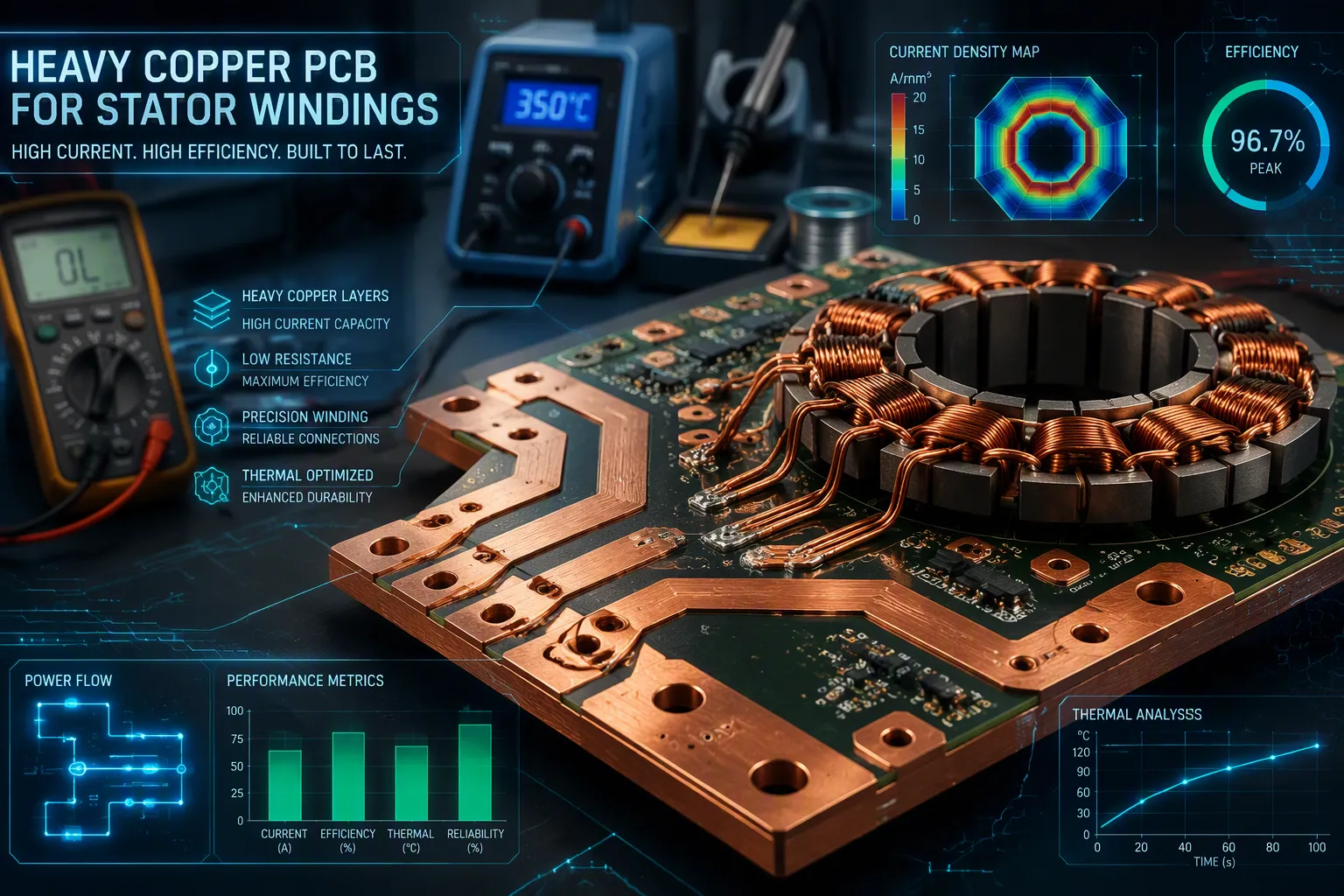
A heavy copper PCB for stator windings uses thick copper traces on a circuit board instead of bulky copper wire. You won’t find thin signal copper here. Standard boards carry small currents, and normal motors use hand‑wound coils around iron cores. Heavy copper changes the math: it lowers winding resistance, raises current density, and enables compact axial flux PCB motor designs. This matters for PCB stator motors, where every millimeter counts. You will learn the design variables, thermal limits, manufacturing steps, testing methods, and when a PCB stator beats a conventional stator. That knowledge helps you choose the right technology for your next build.
Key Takeaways
Heavy copper PCB stators lower winding resistance and raise current density for more torque.
Design choices such as copper thickness and air gap change how well a motor works and how efficient it is.
Vias and cooling manage heat, keeping stators cool under high current.
Automated manufacturing ensures consistent quality and cuts weight by as much as 90%.
PCB stators work great in drones, robots, and HVAC fans where weight and precision are important.
What Is a Heavy Copper PCB Stator
A printed circuit board stator replaces the copper wire coils of a traditional motor with etched copper traces on a circuit board. You get a flat, lightweight component that generates a magnetic field when current flows through those traces. The term heavy copper pcb refers to boards built with much thicker copper than standard signal boards. This thickness changes what the stator can do.
PCB Stator vs. Conventional Stator
A conventional stator uses a heavy iron core wrapped with copper wire. Skilled workers or machines wind that wire into coils by hand or with specialized equipment. The process takes time, adds weight, and limits how small you can make the motor.
A pcb based stator works differently. The conductive traces sit flat on the board surface. No iron core is needed in many axial flux designs. No manual winding step exists. A pcb stator motor can weigh about 60% less than a comparable conventional motor. PrintStator-designed motors can be up to 70% lighter. Raw material use drops by up to 80%. You also avoid the labor-intensive copper windings that drive up conventional motor costs.
Why Heavy Copper PCB Matters
Standard circuit boards use 1 oz copper, which measures about 35 µm or 1.4 mil thick. That works fine for signals. It cannot handle serious current. Heavy copper starts at 4 oz and above. Many pcb stators use 4 oz to 20 oz copper. A 6 oz layer measures roughly 8.4 mils. That extra metal lowers winding resistance and raises current density.
The table below shows how copper weight maps to thickness:
Copper Weight | Approximate Thickness |
|---|---|
0.5 oz | 17 µm (0.7 mil) |
1 oz (standard) | 35 µm (1.4 mil) |
2 oz | 70 µm (2.8 mil) |
3 oz (heavy copper) | 105 µm (4.2 mil) |
Thicker copper carries more current. A 10 mil trace of 1 oz copper handles about 1 A. A 50 mil trace of the same copper handles roughly 5 to 6 A. Heavy copper pushes those limits much higher. This matters for pcb motor design because torque depends on current. More current through the winding means more magnetic force.
Heavy copper also reduces resistive losses. Lower resistance means less heat for the same current. That efficiency gain lets you shrink the motor or push it harder. For pcb stator motors in drones, robotics, or HVAC fans, that combination of low weight and high current capacity is exactly what you need.
The trade-off is cost and manufacturing difficulty. Heavier copper requires wider minimum trace and space rules. A 1 oz board might use 5/5 mil rules. A 3 oz board needs 8/10 mil. Etching also becomes less vertical with thicker copper. These factors raise the price per board. You accept that cost when weight, size, and automation matter more than raw torque density.
How Printed Circuit Board Stator Motors Work
You need to know how these motors work before you can design or pick a PCB stator motor. The science is easy to follow once you see how the parts connect.
Printed Circuit Board Stator Motors Explained
An axial flux pcb motor makes magnetic flux along the motor's axial path. Current moves through the stator coils and creates a magnetic field. That field pushes against permanent magnets placed on the rotor. This makes the rotor spin. This axial field setup gives a more even magnetic field spread across the rotor-stator gap. You get better efficiency and less wasted energy than radial flux designs.
The steps happen in a set order. Drive electronics send phase current into chosen parts of the PCB coils. The conductive traces make a magnetic field across the air gap. That field pushes against the rotor magnets and makes a tangential force. Rotor position feedback or a sensorless method sets the commutation timing. The cycle repeats as the rotor turns and sends mechanical power to the shaft.
A printed circuit board stator uses very thin copper foil set in a parallel layer structure. This design handles high current densities. Vertically stacked multi-layer copper traces use 4 to 6 layers of 35 to 70 μm copper. Vias every 1.5 to 2.5 mm link the layers in parallel. Current spreads evenly within plus or minus 8 percent. The equal cross-section reaches 140 to 420 μm. Current density reaches 8 to 11 A/mm². Vertical copper pillar integration gives another option. Copper pillars 0.4 to 0.6 mm wide carry 60 to 70 percent of total current. Planar trace current density falls from 8 A/mm² to 3 to 4 A/mm². Parallel winding of multi-layer PCBs spreads current density across layers and cuts localized heating.
The Role of Heavy Copper in Torque
Heavy copper pcb sits at the heart of high-torque pcb stators. The reason is plain: thicker copper cuts resistance and boosts current density. You get more current through the windings at the same voltage. More current means more magnetic force. More force means more torque.
Using 3 to 6 oz copper weight instead of standard 1 oz can reach about 50 percent effective fill factor. You can use relaxed 0.15 mm trace width and plus or minus 0.1 mm tolerance. Expected effects include fill factor of 48 to 52 percent and magnetomotive force increase of 35 percent. You keep standard PCB processes. Stepped copper plating puts 6 oz deposition in critical winding zones and 3 oz in transition zones. This keeps current density spread even while using standard photolithography.
The trade-offs matter for pcb motor design. Wider or thicker copper lowers DC resistance and temperature rise. But it needs larger coil area, tighter spacing, and hits manufacturing limits. You must control copper thickness uniformity across layers. Thermal expansion mismatch in thick copper creates risk. You also need to check current density distribution.
PCB thickness affects the magnetic gap. Bearing runout affects clearance. Magnet placement affects back EMF and torque ripple. Trace geometry affects resistance and induced voltage.
These factors work together. A pcb based stator with heavy copper gives you high torque-to-weight ratio and better energy efficiency. PCB stator motors reach efficiencies in the mid-90s. They can be up to 70 percent lighter than traditional options. The ultra-thin pcb stator disc format allows compact axial flux designs. You get these benefits when you balance copper weight against thermal and mechanical limits.
Key Design Variables
You can adjust several things when you design a heavy copper pcb for pcb stators. Each choice affects resistance, current capacity, and torque. Knowing these variables helps you make the right trade-offs for your pcb motor design.
Copper Thickness, Layers, and Trace Geometry
A dual-function layer approach puts 35 μm copper on the outer layer and 70 μm copper on the inner layer. This design boosts flux linkage by 18 to 25 percent without adding parts. Power traces use 3 oz copper, while flux-shaping regions use 1 oz copper. This keeps a standard 4-layer stackup.
Trace width is important. Use 0.8 to 1.5 mm conductor width for high current paths. Use 0.3 to 0.5 mm sections for flux shaping. These wide conductors carry more current. Serpentine traces with 60 to 120 degree bend angles create flux concentration zones. This raises effective flux density by 18 to 25 percent without adding layers.
Layer count changes your options. You can use vertical copper post arrays with 0.3 to 0.6 mm diameter. These link 4 to 6 inner copper layers in parallel at high-current nodes. This makes effective multilayer windings. With a post pitch of 1.2 to 2.0 mm, you boost effective conductor cross-section by 150 to 200 percent compared to single-layer 105 μm copper. Current capacity goes up by 180 to 220 percent. Thermal resistance falls by 35 to 45 percent.
In pcb motor design, wider or thicker copper cuts DC resistance and temperature rise. But it needs larger coil area and tighter spacing. You must balance these factors in your pcb stator design.
Air Gap, Pole Count, and Winding Patterns
Air gap size changes torque ripple and efficiency. Raising air gap to 211 mil can cut torque ripple from about 36 percent to 13 percent. A larger air gap can lower efficiency slightly from 88 to 86 percent.
Pole count shapes how smooth the motor runs. Fractional slot designs where stator teeth are not a multiple of rotor poles soften torque ripple by cutting harmonic resonance. A 2-pole, 12-slot combination has a clear clunky feel. Raising slot count to 15 slots makes performance better.
Winding patterns also matter for smooth torque. Single-layer concentric and basket patterns show little difference in cutting torque ripple. You might pick basket pattern for easier manufacturing and less coil overhang.
These pcb stator motor designs work best when matched to your target torque and efficiency. For pcb stator motors in compact designs, adjusting air gap and pole count gives you fine control. An axial flux pcb motor gains from these careful adjustments.
Stator Design and Stackup
Your choices for the board stackup decide how well a heavy copper PCB stator works under real use. The board material, copper thickness, and board stiffness all affect each other. You cannot change one part without changing the others.
Substrates and Insulation Materials
The base material holds your copper traces and keeps them from touching each other. FR-4 works for many PCB stator builds because it is cheap and strong enough. Polyimide works in hotter places. Materials that carry heat well pull heat away from the windings more effectively. Each option changes how hot the board gets and how well it conducts electricity.
Several material properties matter for PCB motor design. Glass transition temperature (Tg) tells when the board starts to soften. Multi-layer boards using lead-free solder need a Tg above 170°C. Decomposition temperature (Td) must be higher than soldering temperatures of 200 to 250°C. The Z-axis coefficient of thermal expansion (CTE) should stay below 70 ppm/°C to avoid stress from copper mismatch. Dielectric constant (Dk) and dissipation factor (Df) affect signal quality for encoder feedback. Peel strength and flexural strength keep the board whole during heating and cooling. Low moisture absorption and a proper flammability rating make it last longer.
Balancing Copper Weight and Board Thickness
Copper weight and board thickness affect each other in opposite ways. Thicker copper carries more current and moves heat away better. It also makes the board stiffer and heavier. A thicker board adds strength but makes the air gap bigger in some axial flux layouts. You must find the right mix for your PCB stator motors.
Heavy copper processes at 3 oz (105 μm) and above can carry a lot of current. They also make a steadier magnetic field across the PCB stators. How flat and stable the board is directly changes the air gap between stator and mover, so you must keep the layers very even. For multilayer designs, put signal layers in the right order and add special layers for power and ground to cut down electrical noise. Your application area, whether industrial or automotive, creates extra needs like preventing magnetic interference and matching thermal expansion. All these choices affect the PCB stators you build.
Thermal Management
Heat Sources in Heavy Copper Stators
Heat gathers in a heavy copper stator from a few sources. DC resistance in the copper traces makes I²R losses. Running at high speed adds losses that depend on frequency, caused by shifting magnetic fields and current spread. Current also bunches up at corners, narrow spots, pads, and vias. Planar conductors in pcb stators often have less copper fill than wound-wire coils, which raises resistance and heat. The stator sits inside a tight rotating assembly, so cooling paths stay limited. Magnet and bearing temperature limits, laminate and solder-mask margins, and AC losses from rotor-field harmonics add even more limits.
You should never rate current from trace width by itself. Figure out the rating from winding temperature you have checked under your planned load and cooling setup. A PCB stator has more surface area than a copper wire-wound stator. That bigger surface lets it cool more effectively. Since heat loss limits the current through copper, better cooling lets you push higher current or use less copper.
Cooling Strategies and Thermal Vias
You have a few cooling choices, and each one changes the thermal resistance you can get. The table below compares common methods.
Method | External Thermal Resistance |
|---|---|
Heat sink (natural convection) | Under 15°C/W |
Heat sink (forced air convection) | As low as 5°C/W |
Heat sink (liquid cooled) | 1°C/W or lower |
Forced air vs. natural (10 cm² area) | 100°C/W down to 33°C/W |
Infinitum Electric pushed liquid cooling further. They made the motor shaft hollow and put in nozzles to spray fluid right onto the stator surface. This puts coolant on the heat source. Normal air-cooled radial flux motors run at about 3–4 A/mm², while their liquid-cooled PCB stator hits 42–56 A/mm². They first used DEXRON VI automatic transmission fluid and later tried engineered fluids. Direct winding heat exchangers cut peak temperature by 88–102°C compared to jacket cooling. Circular channels in the stator run 14–20°C cooler at high current density. Thermal vias, heat sinks, forced air, and liquid cooling all belong in your pcb motor design toolbox.
Manufacturing Process
Making a heavy copper stator begins with steps you won't find in normal board making. Each stage, from CAM review to final lamination, needs tighter control. You can't handle thick copper the same way as thin signal layers.
Etching, Plating, and Layer Alignment
The process starts with a CAM review. You look at the design data for problems that could affect manufacturing. Pads placed too close to the board edge might expose copper after routing. You change the pad-to-edge clearance to stop that issue. You also add 2.0mm non-plated tooling holes for holding the board. These holes keep the board steady while it's being made.
Etching heavy copper requires wider minimum trace and space rules. Thick copper doesn't etch straight down. The acid eats sideways as it goes deeper. You end up with trapezoid-shaped traces instead of clean rectangles. This undercut changes the final trace width. You have to plan for it in your pcb motor design.
Plating brings another challenge. You need to build copper thickness evenly across the whole board. Differences in plating create weak spots in the conductive traces. These weak spots increase resistance and cause hot spots when the motor runs.
Layer alignment is more important with heavy copper. Thick layers put stress on the board during lamination. The stackup must balance copper weight on each side to stop warping. Heavy 6oz copper needs strict stackup control. Without it, the board can warp or come apart. For a pcb stator, this risk is higher than with normal boards.
Tolerances and Quality Control
Tight tolerances are what separate a reliable stator from one that fails. You must check every measurement. Small holes like 0.35mm are too small to position reliably without special tooling. You swap them for larger holes or add more alignment features.
Mismatches between Gerber files and fabrication notes cause trouble. Solder mask openings, silkscreen polarity, and surface finish details all need to match. You go over all the data before production begins. Customer approvals confirm the design is ready to go.
Quality control makes sure the finished pcb stators meet specs. You test continuity, resistance, and dielectric strength. These tests catch opens, shorts, or insulation failures. For pcb stator motors, even one bad via can ruin performance. The windings must show steady resistance across all phases.
Stackup control stops warping. You measure copper thickness across the board. You check layer alignment after lamination. Boards that pass these checks go on to final routing and delivery. A well-controlled process delivers reliable stators in as little as 18 days.
Testing Procedures
Electrical and Insulation Testing
You must verify every heavy copper pcb stator before it leaves the factory. A single bad via or short ruins motor performance. Start with visual inspection and continuity testing. You examine the board for solder bridges, missing components, and physical damage. Then you check for proper connections and the absence of shorts.
In-circuit testing (ICT) comes next. This fixture-based method verifies component presence, orientation, and value. It also checks for shorts and opens in the circuitry. For the windings, you measure resistance across all phases. The readings must stay steady and match your design targets. Dielectric strength testing confirms the insulation holds up under high voltage. You apply a test voltage between the copper traces and the substrate. Any breakdown means the board fails.
The table below lists key protocols for electrical and insulation verification.
Testing Protocol | Purpose |
|---|---|
In-Circuit Testing (ICT) | Verifies component presence, orientation, and value; checks for shorts and opens |
Visual Inspection and Continuity Testing | Examines for manufacturing defects and verifies proper connections |
Protection Circuit Validation | Tests overcurrent, overvoltage, and thermal protection by simulating faults |
Power-Up and Quiescent Current Measurement | Applies low voltage first, measures quiescent current to detect shorts |
Performance Testing Under Load
After electrical checks pass, you test the pcb stator motors under real load. Dynamic performance characterization measures efficiency, speed regulation, torque response, and thermal performance. You run the motor across its full speed and torque range. You record how much torque it produces at each point. You also track how efficiently it converts electrical power to mechanical power.
Thermal rise is critical. You monitor winding temperature during these tests. The stator must stay within safe limits under continuous load. No-load motor testing comes first. You connect the motor without mechanical load and apply gradually increasing commands. You watch acceleration, noise, and current draw for smooth rotation. Functional testing then subjects the completed board to simulated operating conditions. You apply power and control signals while monitoring outputs. This validates motor driving, feedback sensing, and protection features. Environmental stress screening may follow. This exposes boards to thermal cycling, vibration, and humidity to identify failure mechanisms.
PCB Motors vs. Conventional Motors
Advantages in Weight, Size, and Repeatability
A PCB stator weighs less than 10% of a normal iron-core wound stator with the same power rating. At the component level, weight can drop by up to 90%. The whole machine can be up to 50% lighter. You get a thin, flat shape that fits where a round motor cannot. An axial flux PCB motor uses this shape to make a smaller package.
The automated build process changes everything. A PCB stator motor uses computer‑based manufacturing that does not depend on the worker's skill. You get boards with no empty spots every time. The PCB design removes old twisted copper wires. Wire‑twisting machines are replaced by fully automated, factory‑free PCB making. This makes production simpler and lowers the cost per motor. You also get high flexibility and modular coil shapes.
The table below shows where PCB motors beat conventional BLDC motors.
Performance Metric | PCB Motor Advantage |
|---|---|
Efficiency | Above 90%, up to 94%, IE5 class |
Cogging torque | None at all |
Durability | Fully fixed windings, no insulation stress |
Harmonics | Nearly smooth EMF |
Noise | Clear benefits in low‑power uses |
Turn‑down | Better ability, smaller connected gear |
Limitations and When Conventional Wins
PCB stator motors do not win every match. Copper fill is limited by flat trace and layer limits. Normal three‑dimensional windings often get higher copper fill. This limits torque density in some designs. A toothed conventional design can also beat a coreless PCB design on pure torque.
Think about the decision factors carefully. A PCB stator motor fits thin, flat packages well. A normal wound motor works for more shapes, often round. Winding repeatability favors the PCB method because artwork and PCB processes control it. Cogging favors coreless PCB designs. Customization is easier with PCB stators because you change the design files. Normal motors may need winding‑tool or lamination changes.
Your risk focus differs too. PCB stators have risks with AC copper loss, heat path, flatness, and air gap. Normal motors have risks with winding, insulation, lamination, and assembly variation. Pick normal motors when you need the highest torque density and a round shape works for you.
Applications and Use Cases
Drones, Robotics, and HVAC Fans
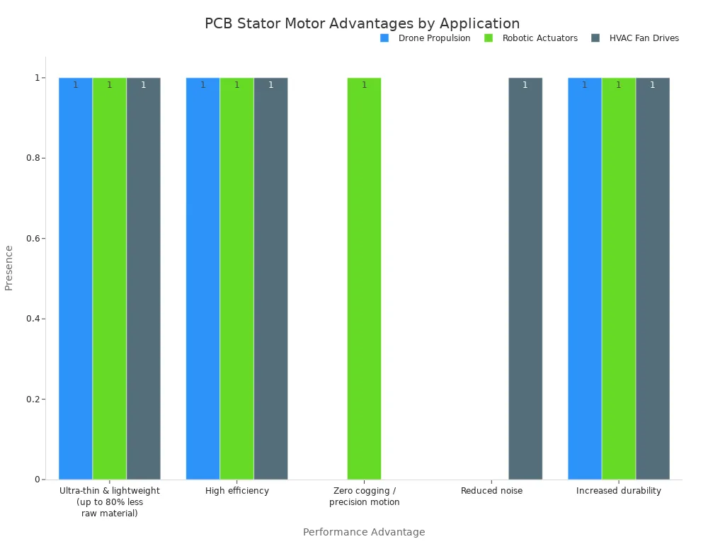
Heavy copper PCB stators show up in products where weight and precision decide success. Drone propulsion gains the most from weight savings. PCB stator motors cut weight by 70–80% compared to traditional wound motors. That means longer flight times or more payload capacity. Few commercial competitors offer PCB-specific design at this level.
Robotic actuators need smooth motion at low speeds. These motors start at 0.3V and produce zero cogging. That makes them good for medical or surgical robotics where precise movement matters. HVAC fan drives benefit from ultra-efficient, quiet, and compact designs. OEMs meet strict efficiency standards while cutting noise and size.
The table below shows which performance advantages apply to each application.
Performance Advantage | Drone Propulsion | Robotic Actuators | HVAC Fan Drives |
|---|---|---|---|
Ultra-thin & lightweight (up to 80% less raw material) | ✓ | ✓ | ✓ |
High efficiency | ✓ | ✓ | ✓ |
Zero cogging / precision motion | — | ✓ | — |
Reduced noise | — | — | ✓ |
Increased durability | ✓ | ✓ | ✓ |
Automotive, Aerospace, and Industrial Pumps
Heavy copper PCB technology has grown well past early prototypes. ECM's PCB stator motors make low levels of EMI. That matters for robotic-assisted surgery, military surveillance, and oceanographic research. Sensitive sensors and monitoring devices work close to these motors.
ECM's PCB stator motors make low levels of EMI, which is very important for robotic-assisted surgery, military surveillance, and oceanographic research where sensitive sensors and monitoring devices work close by. The technology has been put into automated vehicles, industrial and medical robotics, gimbal systems, and maritime transportation, and is now growing into consumer products including electric bikes, HVACR pumps and fans, propulsion motors, and kitchen appliances.
You also see heavy copper in communications equipment, aerospace systems, automotive assemblies, and network energy hardware. The windings in these stators handle high current without adding bulk. Industrial pumps use the same advantage. A compact stator fits into tight housings and runs cooler under continuous load. As materials improve, expect more applications to adopt this technology.
Heavy copper PCB stator windings give you three main benefits. They cut winding resistance, boost current density, and allow compact axial flux shapes. A pcb stator with 3 oz copper or more can handle high current in a flat package.
Focus your review on copper thickness, heat management, and testing. Keep an eye on winding temperature under real load. Pick a pcb stator when weight, size, and automation are more important than raw torque density. Choose a conventional motor when you need the most torque in a round shape.
Expect pcb stator motors to reach more uses as materials get better. Better dielectrics and copper methods will keep expanding what these stators can do.
FAQ
What copper weight should I choose for a pcb stator?
Start with 3 oz copper as your base. Many designs use 4 oz to 20 oz. Thicker copper lowers resistance and raises current density. A dual-function layer approach puts 35 μm copper on outer layers and 70 μm on inner layers. Balance copper weight against thermal limits and manufacturing cost.
How do I manage heat in a heavy copper stator?
Heat comes from resistive losses and eddy currents. Use thermal vias to move heat away from windings. Add heat sinks with forced air for moderate cooling. Liquid cooling works best for high current density. Direct winding heat exchangers cut peak temperature by 88–102°C compared to jacket cooling.
Can pcb stator motors replace conventional motors in every application?
No. PCB stators win on weight, size, and automation. They weigh up to 90% less at the component level. Conventional motors still win on raw torque density. Choose a conventional motor when you need the highest torque in a round shape. Pick PCB designs for thin, flat packages.
What tests confirm a heavy copper stator is ready for use?
Run continuity and resistance checks across all phases. Perform dielectric strength testing to verify insulation. Then test under load to measure torque, efficiency, and thermal rise. Monitor winding temperature during continuous operation. Environmental stress screening with thermal cycling and vibration catches failure mechanisms.
See Also
A Complete Production Technology Guide For Heavy Copper Multilayer PCBs
Key Design Tips For Heavy Copper PCBs Handling High Current
Seven Critical Quality Control Steps For Assembling High Current Heavy Copper PCBs
How Panasonic Copper-Clad Laminates Are Applied In PCB Manufacturing
Applying Horizontal Copper Sinking Technology In Modern PCB Production Processes
