High TG FR4 PCB complete performance guide
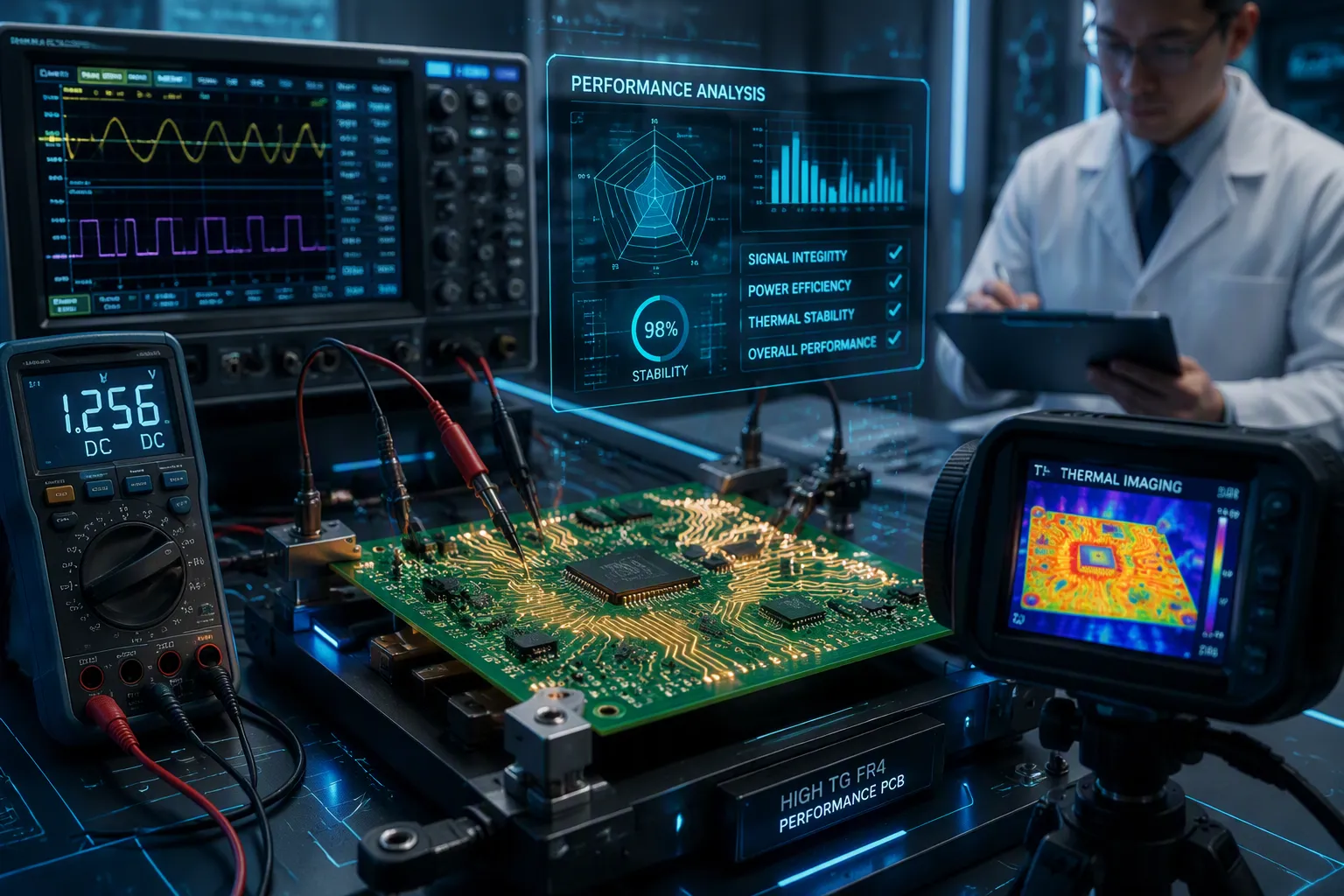
High Tg FR4 is a laminate material with a glass transition temperature high enough to stay rigid during lead-free soldering. Simply put, Tg is the point where the resin softens from a hard state to a rubbery one. This matters because thermal stability stops delamination and keeps plated holes intact under assembly heat. This guide helps you compare options and decide if you need this material. You get practical advice on balancing cost and reliability. The core question is simple: does your design require high tg fr4 pcb, or can standard FR4 handle the job?
Key Takeaways
Keep your board stiff while soldering. Pick High Tg FR4 when reflow temperatures go above 260°C.
Cut down on hole cracks and delamination. High Tg FR4 reduces Z-axis expansion when it gets hot.
Match the material to the temperature. Choose a Tg that is at least 20–30°C higher than your board's highest operating temperature.
Save money on simple designs. Standard FR4 works for boards with few layers and moderate heat.
What Is High Tg FR4 PCB?
Tg explained in plain terms
The glass transition temperature (Tg) marks the point where fr4 changes from a rigid state to a rubbery state. For fr4, this temperature typically falls between 130°C and 180°C. Standard fr4 has a Tg of 130–140°C. A high tg fr4 pcb uses resin that transitions at 170°C or higher. This high tg fr4 grade keeps the board rigid during lead-free soldering.
Why does this matter for you? During reflow, temperatures reach about 260°C. A standard board softens well below that peak. A high tg pcb stays rigid. This rigidity prevents barrel cracking and delamination. The advantages of using a high-tg laminate become clear when you examine the numbers.
Let us compare key high tg pcb material properties. The Z-axis CTE below Tg is 60–70 ppm/°C for standard FR4. For high tg fr4 pcb materials, it drops to 45–55 ppm/°C. That means less expansion in the thickness direction. Decomposition temperature (Td) also improves. Standard FR4 gives you 310–320°C. High tg pcb materials give you at least 340°C. T288—time to delamination at 288°C—jumps from about 5 minutes to over 15 minutes. These high tg pcb material properties matter for multilayer boards and lead-free assembly.
IPC standards and Tg ranges
The industry uses IPC-4101 slash sheets to classify materials. For a high-tg fr4 pcb, the key specifications are /126 and /129. Both require a minimum Tg of 170°C.
IPC-4101 Slash Sheet | Material Type | Tg Value |
|---|---|---|
/126 | High-performance epoxy-based | ≥170°C |
/129 | High-performance epoxy-based | ≥170°C |
/124 | Epoxy-based | ≥150°C |
/101 | Difunctional epoxy-based | ≥110°C |
/121 | Difunctional epoxy-based | ≥110°C |
You can think of these as market labels. Standard-Tg FR4 sits around 130–140°C. Mid-Tg FR4 ranges from about 150–165°C. High tg fr4 starts at 170°C. When you specify a high tg fr4 pcb, these slash sheets give you a reliable benchmark. A high-tg laminate like /126 or /129 ensures consistent performance across suppliers.
This classification helps you pick the right materials for your pcb. If your design sees high operating temperatures, choose a high tg pcb materials grade. Your pcb will resist warpage and maintain dimensional stability.
High Tg FR4 vs. Standard FR4
CTE, Td, and T288 differences
You can see the gap between these two laminates in three key numbers. The table below compares them directly.
Property | Standard FR4 (Tg 130–140°C) | High Tg FR4 (Tg ≥170°C) |
|---|---|---|
CTE (z-axis, below Tg) | 50–70 ppm/°C | 30–40 ppm/°C |
Decomposition Temperature (Td) | 310–320°C | 330–340°C |
Time to Delamination (T288) | <5 minutes | 15–20 minutes |
The z-axis CTE tells you how much the board expands through its thickness as it heats. Standard fr4 expands at 50–70 ppm/°C below Tg. Above Tg, that value often increases by a factor of 3–4 and can reach 200–300 ppm/°C. A high tg fr4 board holds a lower CTE across a broader temperature range. This difference protects plated holes during reflow.
Td and T288 measure how the resin handles extreme heat. Standard fr4 starts to decompose around 310–320°C. High tg fr4 pushes that limit to 330–340°C. The T288 test shows an even sharper contrast. Standard material delaminates in under 5 minutes at 288°C. A high tg pcb survives 15–20 minutes. These high tg pcb material properties give you a real safety margin for lead-free assembly.
When standard FR4 still works
Standard fr4 remains a smart choice for many pcb design projects. A low-layer-count board with through-hole parts or simple SMT does not see extreme thermal stress. Your operating temperature stays moderate. Your assembly profile uses a standard reflow curve. In these cases, the extra cost of high tg fr4 buys you little.
The advantages of high tg fr4 center on thermal and mechanical reliability. This material does not turn your board into a high-frequency laminate. Signal loss at gigahertz frequencies depends on resin chemistry and copper roughness, not Tg alone. If your design needs low loss, look at dedicated RF materials instead.
Consider your worst-case temperature before you upgrade. A thick, multi-layer board with fine-pitch parts benefits from the dimensional stability of high tg materials. A simple two-layer control board may run for years on standard stock. Match the material to the job.
Performance Benefits of High Tg PCB
Lower Z-axis expansion and PTH reliability
You already know heat makes materials grow. In a high tg fr4 pcb, the resin grows much less up and down. This is important because your plated through holes and vias go straight through that direction. When the laminate gets hotter than its Tg, the resin softens and grows faster. That growth pulls on the copper barrel. Over and over, heating and cooling stretch the copper until tiny cracks appear. A high tg pcb keeps the resin system steadier at high temperatures. Less, steadier Z-axis growth directly makes vias more reliable.
The good results of this steadiness show up in real boards. Less Z-axis growth helps via barrels last through thermal cycling. The biggest gain is less Z-axis growth, which directly affects reliability. You get fewer barrel cracks and a longer life in the field.
Less Z-axis growth helps via barrels last through thermal cycling.
The biggest gain is less Z-axis growth, which directly affects reliability.
Lead-free reflow and impedance stability
Lead-free solder pushes your boards through reflow peaks near 260°C. A high tg multilayer pcb must take that heat without splitting inside. The T288 test measures exactly this risk. It records how long a material holds up against delamination at 288°C.
Material Type | Td (°C) | T288 (minutes) |
|---|---|---|
Standard FR4 | 300–310 | only a few minutes |
High-Tg FR4 | 340–350 | above 15 minutes |
For lead-free processes, the industry target for T288 sits near 10 minutes. That gives you a clear benchmark. A high tg fr4 pcb with strong T288 performance takes repeated thermal shocks. Your multilayer stack stays bonded. Your high-density assembly avoids splitting inside.
High Tg FR-4-like materials (Tg +175°C, Td +300°C to +350°C) were tested at 288°C and showed clear signs of delamination in less than 10 minutes.
That quote shows what happens when a material falls short. You want the opposite result. A high tg pcb material properties profile gives you the margin you need.
Warpage also drops during lead-free reflow. The board holds its shape better. That dimensional stability helps your pcb design stay within tolerance. Impedance control improves as a second benefit. Stable geometry means stable trace impedance. Your high-speed signals see less variation across the board.
These high tg benefits go beyond a single reflow cycle. Your boards may go through assembly, rework, and field thermal cycling. Each cycle adds stress. A high tg fr4 handles that stress better than standard fr4. The advantages of high tg materials come from this steady performance under heat.
You should also think about thermal management. A high tg pcb does not carry heat away faster. It simply resists heat damage longer. That difference matters when you pick materials for your next build. Pair high tg fr4 pcb with proper thermal relief and copper balancing. Your boards will reward you with fewer field failures.
High Tg PCB Applications
Automotive and power electronics
Parts under the hood face very high heat. Engine control units, turbocharger controllers, and exhaust gas sensors are in temperatures up to 120°C, with short bursts up to 150°C. You need a laminate that stays hard well above those peaks.
Application | Ambient Temperature | Transient Spikes | Recommended Tg FR4 |
|---|---|---|---|
Automotive Underhood Electronics (ECUs, turbocharger controllers, exhaust gas sensors) | up to 120°C | up to 150°C | 170–180°C |
Power converters in electric car motor drives need even more. Engineers often choose a high tg pcb rated at 170°C or higher. Isola IS410, a common high tg fr4 material, has a Tg of 180°C. These boards stop layers from pulling apart, reduce cracks in plated holes, and keep parts in place as the board gets hot. Less expansion stops layers from moving. That strong shape extends life in the field.
Servers, industrial, and RF designs
Servers and industrial controls pack many layers into small spaces. A high tg multilayer pcb fights warping during assembly and keeps inner layers lined up. Boards with many parts benefit most because each reflow cycle adds stress. Your pcb design gets more safety margin when the resin stays hard through repeated heat shocks.
RF and high-speed designs need a close look. High Tg FR4 does give better electrical performance at higher frequencies than standard fr4. But it is not a replacement for special low-loss laminates. For millimeter-wave work, pick a special material.
These boards still work well for many RF front-ends below 2 GHz. The benefits of high tg materials — stable shape, heat resistance, and reliable plated holes — support high-performance pcbs in mixed-signal products. Pair them with good heat management and copper balance. Your stack-up will handle the heat.
Selection Guide for High Tg PCB
Temperature, layer count, and reflow rules
You need a simple rule to start picking a material. Choose a Tg value that is at least 20 to 30°C higher than your board’s highest constant operating temperature. This gap keeps the resin from entering its rubbery stage during normal use. Keeping this margin helps maintain copper trace adhesion and the reliability of plated through-holes.
Tg is not the same as the board’s maximum operating temperature. A material rated at 170°C can work safely well below that point. The 20 to 30°C gap ensures stable performance. When your resin stays hard, your vias stay intact. Your copper traces stay bonded to the laminate.
Let us apply this rule to real numbers. If your assembly sees a peak operating temperature of 140°C, pick a material with a Tg of at least 170°C. That falls into the high tg category. If your board operates at 150°C, you need a Tg of 180°C or more. Some high tg pcb materials reach up to 200°C. Those give you extra safety margin.
Layer count and board thickness also affect your choice. A two-layer board with simple parts may run fine on standard fr4. A twelve-layer board with dense routing tells a different story. Thicker boards and higher layer counts store more heat during assembly. They also face more stress from Z-axis expansion. Each layer adds another interface that can separate under heat. High-quality materials reduce that risk. The lower CTE keeps inner layers aligned. The stronger T288 performance prevents delamination between stacked prepreg layers.
Consider your reflow profile too. Lead-free assembly peaks near 260°C. Your board must survive that peak without internal damage. Standard fr4 softens well below that temperature. A high tg pcb stays rigid through the entire reflow cycle. If your board goes through multiple reflow passes for double-sided assembly, the advantages multiply. Each cycle tests the laminate. Good materials pass that test more times.
Cost versus reliability trade-offs
This grade costs more than standard FR4. You pay for the advanced resin chemistry and the tighter manufacturing controls. The price premium varies by supplier and volume, but it is real. Your job is to decide when that premium pays off.
Reserve high tg fr4 pcb for designs where thermal stress or long-term reliability justifies the extra expense. Automotive electronics under the hood are a clear case. Power converters and motor drives also qualify. Server boards with many layers and high component density benefit too. These designs fail when internal separation or barrel cracking occurs. The cost of field failure in these applications far exceeds the material premium.
Standard FR4 still works for many boards. A simple control board in a temperature-regulated environment does not need high-quality material. A prototype board with low layer count runs fine on standard stock. Do not upgrade your materials out of habit. Check your worst-case temperature first. Check your layer count. Check your reflow requirements. If none of those push past the limits of high-performance material, save your budget.
Your pcb design choices also affect the decision. Copper balancing reduces warpage even with standard materials. Proper thermal relief pads lower local heating. Good pcb design helps manage CTE mismatches. These techniques extend the usefulness of standard FR4. Use them before you jump to a higher material grade.
Think about long-term reliability. A high-quality materials set gives you better cycling life and lower failure rates in the field. That matters for products with long warranties or hard-to-access locations. The initial cost increase pays back over the product lifetime. For low-stress designs with short expected life, the extra expense adds no value.
The selection guide comes down to matching the material to the job. Do the math on your temperatures. Count your layers. Review your reflow process. Then pick the laminate that fits without overspending.
PCB Manufacturing Tips and Limits
Drilling, lamination, and reflow adjustments
High Tg laminate is harder and more brittle than standard fr4. You must adjust three manufacturing areas to process it successfully: drilling, lamination, and reflow.
Parameter | Adjustment | Rationale |
|---|---|---|
Spindle speed | Slightly lower | Reduces thermal stress; too much speed causes friction heat and resin burning |
Feed rate | Balanced | Too low increases overheating; too high raises drill stress and breakage risk |
Lamination parameters also change. The peak temperature rises to around 200°C compared to 180–190°C for standard fr4. This makes sure the high tg pcb materials cure completely. Controlled ramp rates of 2–5°C/min for heating prevent thermal shock. Cure time runs 60–120 minutes at peak. Apply pressure gradually with temperature so resin is not expelled too violently.
Reflow requires careful tuning. Bake your boards before reflow to remove trapped moisture. Moisture causes delamination when the peak temperature goes past the material's limit. Lower the peak temperature so it stays below the Tg or decomposition temperature. Use a Ramp-Soak-Spike (RSS) profile for mixed-technology assemblies. Extend the soak time to reduce thermal non-uniformity across the high tg pcb.
High-frequency loss and alternatives
Thermal management remains a limitation. This material does not conduct heat away faster than standard FR4. It only resists heat damage longer. For applications needing better heat transfer, consider metal-core or ceramic substrates.
High-frequency loss is another concern. High Tg FR4 offers better electrical performance than standard FR4. But it is not a substitute for dedicated low-loss materials. The dissipation factor at gigahertz frequencies stays far above RF materials.
Consider alternatives when you need more than this grade can deliver. Mid-Tg FR4 works for moderate thermal stress. BT resin offers better thermal and mechanical properties. Polyimide handles extreme temperatures above 260°C. Metal-core boards provide superior heat dissipation.
The advantages of high tg fr4 center on thermal stability and PTH reliability. Choose it for those benefits. Pick another material when you need different properties.
Pcb design choices also affect success. Use proper copper balancing to reduce warpage. Apply thermal relief pads to lower local heating. These techniques help your pcb perform better regardless of the laminate grade you select.
Match Tg to your worst-case assembly and operating temperature, not to habit. Use the 20–30°C margin rule from this guide. A high Tg laminate costs more, so weigh that premium against long-term field reliability. Standard fr4 still works for low-stress, low-layer-count boards. Run these checks on your next stack-up review:
Does peak reflow temperature exceed what standard materials handle?
Do you run many layers or a thick stack?
Will the product see repeated thermal cycling?
Does your pcb design need tight impedance control?
If you answer yes to any question, the advantages of high Tg FR4 likely justify the extra cost.
FAQ
Can I mix standard FR4 and High Tg FR4 in the same stack-up?
You can, but avoid it. Mixing different Tg grades creates uneven expansion between layers during reflow. That mismatch stresses your boards. Stick to one consistent material system for best reliability.
Does High Tg FR4 improve signal speed?
No. High Tg FR4 improves thermal stability, not signal speed. Signal loss at high frequencies depends on resin chemistry and copper roughness. For multi-gigahertz designs, choose dedicated low-loss laminates instead.
How do you verify genuine High Tg FR4 from a supplier?
Ask for the IPC-4101 slash sheet number. Grades /126 or /129 guarantee a minimum Tg of 170°C. You can also request a DSC test report from the lot. Always confirm which grade of fr4 you receive.
Is the higher cost of High Tg FR4 worth it?
Yes, for thermally demanding designs. The main advantages include lower Z-axis expansion and stronger T288 performance. Reserve the premium for boards that face lead-free reflow, high operating temperatures, or repeated thermal cycling.
Does a thick board always need High Tg FR4?
Not always. A thick, simple two-layer board with through-hole parts runs fine on standard FR4. A thick, multi-layer board benefits more because its higher layer count and denser routing create more thermal stress.
See Also
High TG FR4 Laminate PCBs Deliver Superior Performance In Extreme Temperatures
Guide To Production Technology For Heavy Copper Multilayer Printed Circuit Boards
Combining Rogers Material With TG170 For Hybrid PCB Fabrication Explained
Understanding High-Speed PCBs And Their Role In Modern Electronics
PCB Fabrication Manufacturer Capabilities And LT CIRCUIT Solutions For Complex Designs
