PCB Stator Dimensional Accuracy, Flatness and Reliability
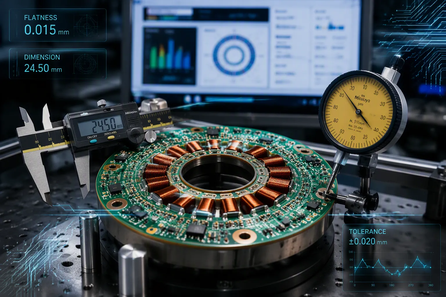
PCB stators need to be the right size and shape. This means each copper trace lines up with the spot it was designed for. They also need to be flat and reliable.
Flatness means the stator surface sits in one single plane.
Reliability means the stator keeps these qualities even under heat and mechanical stress.
These traits directly decide motor efficiency, steady torque, and how long it lasts. Dimensional accuracy in the windings cuts down on resistive losses. A flat air gap gives steady torque. A reliable stator stops early failure.
This article looks at the material and process factors behind dimensional accuracy, failures from poor control, and manufacturing methods for reliable PCBs. It also gives practical advice for engineers.
Key Takeaways
Accurate copper traces make motors work better and waste less energy.
A flat stator keeps the air gap even, which gives smooth torque and less shaking.
Reliable stators stand up to heat and stress, and they last nine times longer than wire-wound ones.
A balanced copper design and low-CTE materials stop warping during manufacturing.
Pick suppliers that use AOI, CMM, and thermal cycling to ensure quality.
Why Accuracy, Flatness, and Reliability Matter
These three qualities have a direct effect on how well a motor works and how long it lasts. A PCB part does its best when all three properties stay within the set limits. Engineers need to see how they work together to make smart design choices. Each quality supports the others, which helps the motor run at its best.
Dimensional Accuracy and Motor Efficiency
A motor uses printed copper traces to make windings. How exact each trace is matters for the motor to work right. Traces must match the exact spots and widths from the design. During use, each trace lines up with magnets in the rotor. Small shifts cause energy losses that lower efficiency. These losses show up as heat instead of useful power. Over time, heat buildup makes performance worse.
Printed windings are more exact than copper wire wound by hand. Photolithographic steps set each trace spot with great precision. This process removes the differences found in normal winding methods. Every unit from a production run acts almost the same. This sameness across the batch gives designers trust in their math. It also allows tighter design limits and higher power density in the final motor.
Exact copper patterns cut down on resistive losses inside the winding traces. Current moves through a path that matches the design perfectly. There is no extra copper or wasted space in the pattern. The motor uses less power to make the same torque. Efficiency gains reach a few percentage points over equal wire-wound designs. These gains make batteries last longer in portable devices. They also cut power costs for industrial motors that run all the time.
Makers keep trace width and spacing within tight limits. These limits stay the same across thousands of boards in one batch. Designers count on this steadiness when figuring expected motor performance. The whole system runs closer to its theoretical limits. Engineers push designs further when they know the winding pattern matches the spec exactly.
Flatness, Air Gap, and Reliability
Flatness controls the air gap between the fixed board and the rotor. This gap must stay even around the whole circle. Any change shifts the magnetic force between the two parts. Torque output moves up and down as the rotor passes through tight or loose zones. The result is uneven spin and vibration. Vibration speeds up bearing wear and shortens motor life by a lot.
A flat surface makes a steady air gap for consistent operation. The rotor sees the same spacing at every degree of turn. Torque output stays smooth and easy to predict in all conditions. Motors that need exact positioning gain the most from this quality. Servo motors, robotics, and medical devices need this level of control. Any shift hurts performance in these sensitive systems.
The rotor and stator assembly needs a flat surface to fit together right. A warped part causes assembly problems during manufacturing. The motor housing may not close right with a bent component inside. Assembly line workers struggle to fit parts that should slide together with ease. Rejects go up and production slows down. These issues raise manufacturing costs and delay delivery to customers.
Long service life sets well-built designs apart from poor ones. A patented design shows better reliability than normal wire-wound units. This gain comes from removing failure modes built into copper wire. Winding shorts and insulation breakdowns happen less often. The motor keeps running under heat and mechanical stress that would harm wire windings.
These pcbs hold their shape through temperature cycles and extend motor life. The component does not warp when the motor gets to operating temperature. The air gap stays stable even after thousands of thermal cycles. This steadiness removes a common failure path that troubles wire-wound stators. Engineers who set these requirements at the design stage avoid costly problems later.
Factors Behind Dimensional Stability in PCB Manufacturing
Dimensional stability in pcb manufacturing means keeping exact sizes and flatness when facing heat, humidity, and mechanical stress. A stator that changes shape during production or use will not do its job. Engineers must know what causes this stability to design boards that work as planned.
Material Behavior Under Thermal and Humidity Stress
Heat makes materials grow. Every copper-clad material changes size as it gets hotter. This movement happens in all directions, but the Z-axis causes the most problems. Growth along Z harms metallized holes and circuits. A material with a high coefficient of thermal expansion moves more for each degree of temperature change. That movement puts stress on plated holes and breaks connections.
Iron-base and aluminum-base substrates grow much less than general resin substrates. Their coefficient of thermal expansion is closer to copper's value. This match keeps printed circuit quality high and reliability strong. Metal-base PCBs can serve as both the circuit board and the stator substrate of small precision motors. This dual role links PCB thermal properties straight to stator dimensional accuracy.
Humidity brings another stress. Resin materials soak up moisture and swell. This swelling changes dimensions and creates stress inside. The board may warp as moisture moves through the layers. Thermal cycling makes the problem worse. Repeated heating and cooling pulls moisture in and out. Each cycle adds stress until the board fails.
Process and Design Choices That Affect Flatness
Flatness is a key requirement for PCB stator manufacturing. Several process steps control whether the finished board stays flat. Imaging and etching form repeatable coil patterns while controlling conductor width, spacing, and copper balance. Layer registration and lamination line up multilayer windings and control finished thickness and warpage. Accurate layer registration keeps each copper layer in its exact spot. Poor layer-to-layer registration shifts windings out of line and hurts motor performance.
Copper balance matters because uneven copper distribution creates stress inside. The board bends to ease that stress during heating and cooling. A balanced design keeps copper even across the panel. This balance cuts bow and twist after lamination and reflow.
Warp and twist come from asymmetric copper distribution and unbalanced heating/cooling. If your board bends after reflow, lamination is often the root cause. ... For high-layer-count boards, do they use low-flow prepregs and balanced copper design?
Lamination cycles press layers together under heat and pressure. The resin flows and cures during this step. Cooling after lamination locks in whatever stress the stack-up created. A well-controlled cycle with balanced copper makes a flat board. A poor cycle causes board warpage that no later step can fix.
PCB stator technology allows customization to exact performance and dimensions for the application. Designers set dimensional tolerances and machining tolerances to match each motor's needs. They adjust layer count, copper thickness, and substrate material. This flexibility lets engineers meet tight tolerances without overpaying for needless precision. The flatness of the workpiece depends on these choices working together from the start.
Problems Caused by Poor Dimensional Control
Poor control of dimensions causes problems that go far past the factory floor. A stator that leaves the line with errors will break down in the field. Engineers must know these failure paths so they can stop them.
Assembly Failures and Performance Loss
A stator with bad dimensional accuracy will not fit into its housing. The mounting holes may not line up with the motor frame. Workers push parts together and harm components while putting them in. These assembly failures and reliability risks drive up production costs and hold back shipments. A pcb with warpage makes the same kind of trouble. The board will not sit flat against the heat sink or mounting surface. Screws strip, connectors line up wrong, and the whole unit fails inspection.
Board warpage also hurts positioning accuracy during automated assembly. Pick-and-place machines cannot put components on a surface that bends. Solder joints crack when the board flexes during reflow. These defects may not appear until the motor runs under load. By that point, the customer has already put in the product. Recalls and warranty claims come next.
Consequences in Motor and Drive Applications
A motor built with out-of-spec parts will not give steady torque. The air gap changes as the rotor turns past high and low spots. This variation causes torque ripple and vibration. Bearings wear out faster, and the motor makes noise that is not wanted. In high-speed applications, these problems get worse. The system may fail all the way under continuous operation.
A non-flat or non-parallel magnet will create uneven air gaps, leading to irregular magnetic field distribution. This, in turn, causes issues like torque ripple in motors. For example, in a high-speed BLDC motor, a flatness error of just 0.01mm can result in noticeable vibration and noise, as well as increased wear on bearings.
Drive systems also suffer when tolerances drift. A servo motor cannot hold position if the stator does not meet its flatness spec. The controller fights the mechanical error and gets too hot. Loose tolerances in the stack-up create bow and twist that no control algorithm can fix. The motor loses efficiency, and the drive trips on overcurrent faults. These failures cost time and money in industrial settings where downtime is expensive.
How Manufacturers Deliver Reliable PCBs
Advanced Materials and Precision Process Controls
Choosing the right material is key for keeping PCB parts stable in size and shape. Polyimide boards keep their strength and electrical insulation even at high temperatures. Ceramic-filled boards do not separate into layers and keep their shape under constant heat. High-Tg boards last longer because they resist layer separation when hot. Low-CTE boards expand less with heat, which helps them stay flat as temperatures change.
Material Type | Contribution to Dimensional Stability |
|---|---|
Polyimide substrates | Maintain mechanical integrity and electrical insulation at elevated temperatures |
Ceramic-filled substrates | Resist delamination and preserve dimensional stability under continuous high-temperature exposure |
High-Tg laminates | Enhance long-term reliability by resisting delamination under thermal stress |
Low-CTE laminates | Reduce thermal expansion mismatch, supporting dimensional stability |
Good process controls turn these materials into working stators. Accurate layer registration puts each copper layer exactly where it should be. Tight machining limits on the stator shape make sure it fits well in the motor housing. Special design software improves copper shapes and winding patterns for high efficiency and strong torque. This method gives high power density with very short length and low weight. PCB stator motors can reach up to 20 kW power, 30,000 RPM, and 100 Nm torque. They also reduce weight by up to 70% and mass by 30% compared to other designs. Multiple PCB motors can stack on one shaft for even more power in the same space.
Inspection and Quality Assurance Methods
Manufacturers check size and flatness at many inspection steps. Automated optical inspection (AOI) finds trace defects and alignment errors after etching. Coordinate measuring machines (CMM) check flatness and machining accuracy by comparing to the design file. Thermal cycling tests heat and cool finished stators many times. These tests confirm the board keeps its shape and electrical properties through the temperature changes a motor faces during use.
Quality assurance goes beyond the factory. High power density, less cogging, and design flexibility all help make the motor reliable in real use. Well-made PCB stators last longer because they avoid winding shorts and insulation failures that happen in wire-wound designs. They also help the environment by using less copper and making less waste during production. Engineers looking for precise, reliable PCB stators should make sure the supplier always does AOI, CMM, and thermal cycling as standard steps, not optional add-ons.
Practical Tips for Engineers
Design Rules and Tolerance Planning
Engineers need to set size limits before they start the layout. They begin with the motor's air gap goal and move backwards. This method connects each trace width and layer alignment to motor performance. A stator that meets its limits at every step will keep its shape in real use.
Designers should look at copper balance across the panel early. Uneven copper causes stress inside during lamination and reflow. That stress causes warping that later steps cannot fix. Designers need to keep copper spread even and plan symmetric layers. They also need to set flatness limits that fit the way parts are built.
Planning tolerances requires thinking about how materials act. Low-CTE laminates grow less when hot, helping accuracy and repeatability through heat changes. Engineers must set tolerances for layer alignment, final thickness, and hole position. Every tolerance should come from a real need in the motor. Too tight tolerances increase cost but do not improve performance.
Supplier Evaluation Checklist
A supplier's process controls decide if a pcb stator meets its goals. Engineers should ask which standards the supplier uses and how it checks results. The table below shows key standards and how they help qualify the stator.
Testing Domain | Applicable Standard | Relevance to Stator Qualification |
|---|---|---|
Partial discharge in motor windings | IEC 60034-27 | Specifies partial discharge measurement for winding insulation |
Partial discharge measurement | IEC 60270 | Defines how to measure PD magnitude in insulation systems |
PCB material and process testing | IPC-TM-650 | Covers dielectric properties and impedance test methods |
Electronic assembly acceptability | IPC-A-610 | Defines acceptance criteria for manufactured assemblies |
Solder joint reliability | IPC-9701 | Specifies thermal cycling and mechanical stress tests |
PCB design (creepage/clearance) | IPC-2221B | Defines creepage and clearance for high-voltage design |
Dielectric strength | ASTM D149 | Covers dielectric strength testing of insulating materials |
Reliability prediction | MIL-HDBK-217F | Provides failure rate models for reliability predictions |
Engineers should make sure the supplier does automated optical inspection, coordinate measuring machine checks, and thermal cycling as normal steps. They also need to ask how the supplier keeps position accuracy during multi-layer alignment. A supplier that records these methods will send stators that keep their size.
Dimensional accuracy, flatness, and reliability form one system. Exact traces cut losses, a flat surface holds the air gap steady, and a stable stator keeps both traits through heat and stress. A flatness error of just 0.01 mm can cause vibration and bearing wear.
Engineers achieve these qualities through deliberate design, careful material choice, and precision-focused manufacturing partners. Balanced copper, low-CTE laminates, and controlled lamination prevent warpage before it starts.
Treat these attributes as non-negotiable specifications, not optional refinements. A pcb stator that misses them will fail in the field.
Demand keeps rising for compact, high-efficiency motors. Reliable pcbs will decide which designs reach 20 kW, 30,000 RPM, and 100 Nm torque in smaller packages.
FAQ
What flatness tolerance do precision PCB stators require?
High-performance motors need flatness tolerances as tight as 0.01 mm. A gap this small can cause shaking, noise, and bearing wear. PCB stator flatness directly affects how steady the air gap stays and how well the motor works.
How does thermal cycling test pcb stator reliability?
Thermal cycling heats and cools the pcb stator many times. This test shows the board keeps its shape and electrical properties. Motors face similar temperature changes during use. Passing this test proves the motor will last a long time.
What standards apply to pcbs used in stator applications?
IPC-A-610 sets the rules for accepting electronic assemblies. IEC 60034-27 defines how to measure partial discharge in winding insulation. These standards guide how stator assemblies are made and tested.
See Also
Achieving Flatter Electroplated Filled Holes In HDI PCB Laser Drilling
Becoming An Expert In PCB Production Using Press-Fit Holes
Grasping Vertical Continuous Plating For Copper Thickness Tolerance Control
Guide To Rigid PCB Materials Processes And Industrial Quality Standards
Mastering PCB Manufacturing Quality Control Techniques And Best Practices
